SFX-TMC3GLaunch monitor
TrackMan A/S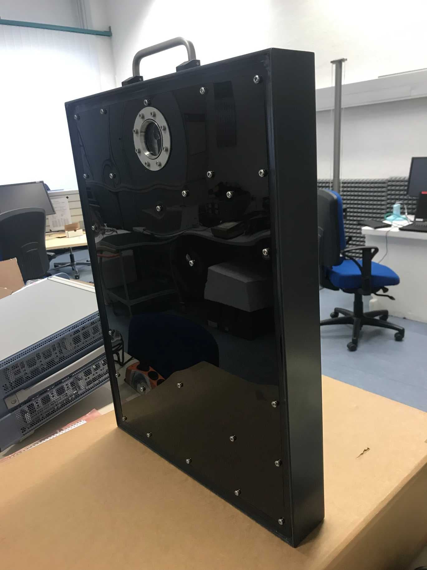
Click to zoom
Application Details
- Equipment Class
- FDS - Part 15 Field Disturbance Sensor
- Date of Grant
- Mar 11, 2020
- Application Purpose
- Original Equipment
- Date of Application
- Mar 11, 2020
- Equipment Note
- Launch monitor
- Frequency Range
- 10500.00000000 - 10550.00000000
- Company
- TrackMan A/S
- Country
- Denmark
Documents & Files
Document Text
Text extracted from the exhibit documents filed with the FCC. Open a document above to read the original.
Users Manual
Issue 5, March. 2020 TrackMan A/S · www.TrackMan.com · Stubbeled 2 · 2950 Vedbæk Denmark · +45 4557 0850 Page 1 of 19 TrackMan™ Radar unit Installation and Safety Instruction TrackMan Baseball Field Radar Type: TMC3G Issue 5, March. 2020 TrackMan A/S · www.TrackMan.com · Stubbeled 2 · 2950 Vedbæk Denmark · +45 4557 0850 Page 2 of 19 Contents 1 Introduction ...................................................................................................................................................... 3 2 Safety Instructions ............................................................................................................................................. 4 2.1 Regulatory Notice ................................................................................................................................................. 4 2.2 Warning: Radiation Hazard .................................................................................................................................. 5 2.3 Caution: Safety precautions ................................................................................................................................. 5 3 Installation instructions ..................................................................................................................................... 6 3.1 System description ................................................................................................................................................ 6 3.2 System specifications. ........................................................................................................................................... 8 3.2.1 Radar. .......................................................................................................................................................... 8 3.2.2 USB Extension Connection Box ................................................................................................................... 9 3.2.3 Backfield Connection Box. .......................................................................................................................... 9 3.3 TrackMan™ Radar unit, model TMC3G. ............................................................................................................. 10 3.4 TrackMan™ USB Extension Connection Box. ...................................................................................................... 11 3.5 TrackMan™ Backfield Connection Box. .............................................................................................................. 11 3.6 Setting up the system. ........................................................................................................................................ 11 3.6.1 PLUGGABLE EQUIPMENT. ......................................................................................................................... 11 3.6.2 PERMANENTLY CONNECTED EQUIPMENT. ............................................................................................... 12 3.6.3 Grounding. ................................................................................................................................................ 12 3.6.4 Connecting mains cable inside the USB Extension Connection Box. ........................................................ 12 3.6.5 Connecting mains cable inside the Backfield connection box. ................................................................. 14 3.6.6 Mains Cable............................................................................................................................................... 15 3.6.7 Setting up the system ............................................................................................................................... 16 3.6.8 Pole mount of the Radar ........................................................................................................................... 16 3.6.9 Pole mount of the backfield connection box ............................................................................................ 18 3.6.10 Pole mount of the USB Extension connection box ............................................................................... 19 Issue 5, March. 2020 TrackMan A/S · www.TrackMan.com · Stubbeled 2 · 2950 Vedbæk Denmark · +45 4557 0850 Page 3 of 19 1 Introduction This document provides instructions and warning in order to safely install and operate the TrackMan Baseball Stadium Radar TMC3G Radar unit This document does not describe the TrackMan™ application software and how to operate it. This is provided in separate document. All electrical installation shall be made in accordance with the local electrical standards or local regulations. Issue 5, March. 2020 TrackMan A/S · www.TrackMan.com · Stubbeled 2 · 2950 Vedbæk Denmark · +45 4557 0850 Page 4 of 19 2 Safety Instructions 2.1 Regulatory Notice Regulatory Notices Installation must be performed by qualified personnel only and must conform to all local codes. FCC/ISED Notices This device complies with the FCC and ISED Canada radiation exposure limits. This equipment should be installed and operated with minimum distance 20 cm between the device and your body. This device complies with part 15 of the FCC Rules. Operation is subject to the following two conditions: (1) This device may not cause harmful interference, and (2) this device must accept any interference received, including interference that may cause undesired operation. NOTE: This device has been tested and found to comply with the limits for a Class A digital device, pursuant to part 15 of the FCC Rules. These limits are designed to provide reasonable protection against harmful interference in a residential installation. This device generates, uses and can radiate radio frequency energy and, if not installed and used in accordance with the instructions, may cause harmful interference to radio communications. However, there i…
Text truncated - open the document above for the full version.
External Photos
Annex A 1-8298/19-01-01_AnnexA External photos of the Equipment Under Test This addendum is electronically signed and valid without handwritten signature. For verification of the electronic signatures, the public keys can be requested at the testing laboratory. Document authorized: Meheza Walla Lab Manager Radio Communications & EMC CTC advanced GmbHUntertuerkheimer Str. 6-10 66117 Saarbruecken / Germany Phone: +49 681 5 98 - 0 Fax: +49 681 5 98 - 9075 web: ctcadvanced.com e-mail: [email protected] Photos Photo 1 Photo 2 2019-10-10Document No. 1-8298/19-01-01_AnnexA2/6 Photo 3 Photo 4 2019-10-10Document No. 1-8298/19-01-01_AnnexA3/6 Photo 5 Photo 6 2019-10-10Document No. 1-8298/19-01-01_AnnexA4/6 Photo 7 Photo 8 2019-10-10Document No. 1-8298/19-01-01_AnnexA5/6 Document history VersionApplied changesDate of release initial release2019-10-10 - END OF DOCUMENT - 2019-10-10Document No. 1-8298/19-01-01_AnnexA6/6
ID Label/Location Info
TMC3G External pictures Front view, radarSide view, radarRear view, radar TMC3G External pictures Plug view and label position on rearpart of radar Rating label, radar TMC3G Internal pictures Rearview, radar Rx Tx Camera Rx RCM board Rx Inclinometer Rx USB Hub TMC3G Internal pictures TX/RX antennas & RCM board with SMA-view TMC3G Internal pictures RCM board TMC3G Internal pictures Front view, radar Extension box External pictures Plug and lid view of Extension boxSide view and label position Rating label, Extension box of extension box Extension box Internal picture Front view, extension box N LT3,15AH Back field box External pictures Plug and lid view of Back field boxSide view and label position Rating label, of back field box Back field box Back field box Internal picture Front view, back field boxZoom in on ac-dc converter, back field box
Internal Photos
TMC3G External pictures Front view, radarSide view, radarRear view, radar TMC3G External pictures Plug view and label position on rearpart of radar Rating label, radar TMC3G Internal pictures Rearview, radar Rx Tx Camera Rx RCM board Rx Inclinometer Rx USB Hub TMC3G Internal pictures TX/RX antennas & RCM board with SMA-view TMC3G Internal pictures RCM board TMC3G Internal pictures Front view, radar Extension box External pictures Plug and lid view of Extension boxSide view and label position Rating label, Extension box of extension box Extension box Internal picture Front view, extension box N LT3,15AH Back field box External pictures Plug and lid view of Back field boxSide view and label position Rating label, of back field box Back field box Back field box Internal picture Front view, back field boxZoom in on ac-dc converter, back field box
Test Report
BNetzA-CAB-02/21-102 TEST REPORT Test report no.: 1-8298/19-01-03 Testing laboratory Applicant CTC advanced GmbH Untertuerkheimer Strasse 6 – 10 66117 Saarbruecken / Germany Phone: + 49 681 5 98 - 0 Fax: + 49 681 5 98 - 9075 Internet: http://www.ctcadvanced.com e-mail: [email protected] Accredited Testing Laboratory: The testing laboratory (area of testing) is accredited according to DIN EN ISO/IEC 17025 (2005) by the Deutsche Akkreditierungsstelle GmbH (DAkkS) The accreditation is valid for the scope of testing procedures as stated in the accreditation certificate starting with the registration number: D-PL-12076-01 Trackman Stubbeled 2 2950 Vedbæk / DENMARK Phone: +45 4557 0850 Contact: Soeren Carlsen e-mail: [email protected] Phone: Manufacturer Trackman Stubbeled 2 2950 Vedbæk / DENMARK Test standard/s FCC - Title 47 CFR Part 15 FCC - Title 47 of the Code of Federal Regulations; Chapter I; Part 15 - Radio frequency devices RSS - 210 Issue 9 Annex F Spectrum Management and Telecommunications Radio Standards Specification - Licence-Exempt Radio Apparatus: Category I Equipment RSS - Gen Issue 5 Spectrum Management and Telecommunications Radio Standards Specification - General Requirements for Compliance of Radio Apparatus For further applied test standards please refer to section 3 of this test report. Test Item Kind of test item: Field Disturbance Sensor Model name: TMC3G FCC ID: SFX-TMC3G IC: 10140A-TMC3G Frequency: 10.50 – 10.55 GHz Antenna: Integrated antenna Power supply: 125 V AC Temperature range: -15°C to +50°C This test report is electronically signed and valid without handwritten signature. For verification of the electronic signatures, the public keys can be requested at the testing laboratory. Test report authorized: Test performed: p.o. Karsten Geraldy Meheza Walla Lab Manager Lab Manager Radio Communications & EMC Radio Communications & EMC Test report no.: 1-8298/19-01-03 © CTC advanced GmbH Page 2 of 49 1 Table of contents 1 Table of contents ............................................................................................................................................ 2 2 General information ....................................................................................................................................... 3 2.1 Notes and disclaimer .......................................................................................................................... 3 2.2 Application details ............................................................................................................................... 3 2.3 Test laboratories sub-contracted ...................................................................................................... 3 3 Test standard/s, references and accreditations .......................................................................................... 4 4 Test environment ............................................................................................................................................ 5 5 Test item .......................................................................................................................................................... 5 5.1 General description ............................................................................................................................. 5 5.2 Additional information ........................................................................................................................ 5 6 Description of the test setup ......................................................................................................................... 6 6.1 Shielded semi anechoic chamber ...................................................................................................... 7 6.2 Shielded fully anechoic chamber ...................................................................................................... 9 6.3 Radiated measurements > 18 GHz ................................................................................................... 10 6.4 Radiated measurements > 50/85 GHz.............................................................................................. 10 6.5 AC conducted .................................................................................................................................... 12 7 Sequence of testing ..................................................................................................................................... 13 7.1 Sequence of testing radiated spurious 9 kHz to 30 MHz ............................................................... 13 7.2 Sequence of testing radiated spurious 30 MHz to 1 GHz .............................................................. 14 7.3 Sequence of testing radiated spurious 1 GHz to 18 GHz .............................................................. 15 7.4 Sequence of testing radiated spurious above 18 GHz .................................................................. 16 7.5 Sequence of testing radiated spurious above 50 GHz with external mixers .............................. 17 8 Measurement uncertainty ............................................................................................................................ 18 9 Summary of measurement results ............................................................................................................. 19 10 Measurement results ................................................................................................................................ 20 10.1 Field strength of emissions (wanted signal) ............................................................................... 20 10.2 Occupied bandwidth (99% bandwidth) ........................................................................................ 23 10.3 Field strength of emissions and band edge (radiated spurious) .............................................. 24 10.4 Conducted…
Text truncated - open the document above for the full version.
Test Setup Photos
Annex D 1-8298/19-01-01_AnnexC Setup photos of the Equipment Under Test This addendum is electronically signed and valid without handwritten signature. For verification of the electronic signatures, the public keys can be requested at the testing laboratory. Document authorized: Meheza Walla Lab Manager Radio Communications & EMC CTC advanced GmbHUntertuerkheimer Str. 6-10 66117 Saarbruecken / Germany Phone: +49 681 5 98 - 0 Fax: +49 681 5 98 - 9075 web: ctcadvanced.com e-mail: [email protected] Photos Photo 1 Photo 2 2019-10-10Document No. 1-8298/19-01-01_AnnexC2/4 Photo 3 Photo 4 2019-10-10Document No. 1-8298/19-01-01_AnnexC3/4 Document history VersionApplied changesDate of release initial release2019-10-10 - END OF DOCUMENT - 2019-10-10Document No. 1-8298/19-01-01_AnnexC4/4
Contact Information
Applicant
Morten Didriksen(Engineer)
Test Firm
cetecom advanced GmbHGerald Schmidt
Technical Specifications
| # | Rule Parts | Frequency Range | Power Output |
|---|---|---|---|
| 1 | 15.245 | 10.50 GHz - 10.55 GHz | - |
Other Applications from TrackMan A/S

SFX-TMB0201
May 22, 2023TrackMan iO
Equipment Class
FDS - Part 15 Field Disturbance Sensor
SFX-TMB4A
Mar 29, 2020Launch monitor
Equipment Class
FDS - Part 15 Field Disturbance Sensor
SFX-TMANIII
Apr 02, 2012Field Disturbance Sensor
Equipment Class
FDS - Part 15 Field Disturbance Sensor