SGWIPS2007VSVehicle Detection Sensor
IPS Group Inc.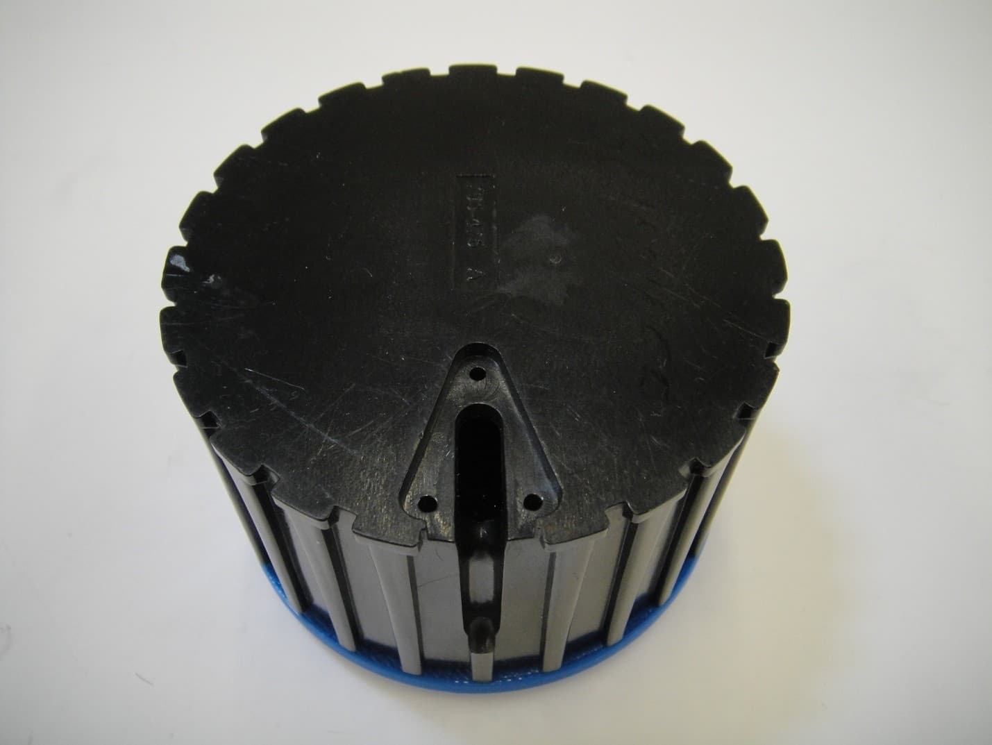
Click to zoom
Application Details
- Equipment Class
- DXX - Part 15 Low Power Communication Device Transmitter
- Date of Grant
- Apr 10, 2014
- Application Purpose
- Original Equipment
- Date of Application
- Apr 10, 2014
- Equipment Note
- Vehicle Detection Sensor
- Frequency Range
- 410.00000000 - 430.00000000
- Company
- IPS Group Inc.
- Country
- United States
Documents & Files
Document Text
Text extracted from the exhibit documents filed with the FCC. Open a document above to read the original.
Users Manual
FCC Rules Compliance Statement (Part 15.19) The enclosed hardware device complies with Part 15 of the FCC Rules. Operation is subject to the following two conditions: (1) This device may not cause harmful interference, and (2) This device must accept any interference received including interference that may cause undesired operation. Warning (Part 15.21) Changes or modifications not expressly approved by IPS Group, Inc. could void the user’s authority to operate the equipment. Manufacturer is not responsible for any radio or TV interference caused by unauthorized modifications to this equipment. Label Warning Statement The enclosed hardware device complies with Part 15 of the FCC Rules. Operation is subject to Part 15 of the FCC Rules. Operation is subject to the following two conditions: (1) This device may not cause harmful interference, and (2) This device must accept any interference received including interference that may cause undesired operation. Compliance Statement (Part 15.105(b)) This equipment has been tested and found to comply with the limits for a Class B digital device, pursuant to Part 15 of the FCC Rules. These limits are designed to provide reasonable protection against harmful interference in a residential installation. This equipment generates, uses and can radiate radio frequency energy and, if not installed and used in accordance with the instructions, may cause harmful interference to radio communications. However, there is no guarantee that interference will not occur in a particular installation. If this equipment does cause harmful interference to radio or television reception, which can be determined by turning the equipment off and on, the user is encouraged to try to correct the interference by one or more of the following measures: • Reorient or relocate the receiving antenna • Increase the separation between the equipment and receiver • Connect the equipment into an outlet on a circuit different from that to which the receiver is connected • Consult the dealer or an experienced radio/TV technician for help Vehicle Sensor Theory IPS Vehicle Detection Sensor provides a reliable and secure detection system which detects the presence and absence of a vehicle in a public or garage parking space. The IPS sensor uniquely directs all sensing information via the IPS single or multispace parking meter cellular communications backbone. The parking locations weather they are located on a city street or parking structure will detect whatever is parked over it. This build in an added measure of security not only does it detect when a vehicle is located at a parking location it will also detect when it is vacant so if a vehicle is abandon, stolen or has been left on the street somewhere it can be immediately located and it will time date stamp the actual event. It will also tell the city workers that have shut down specific parking locations due to either road work or an event if someone has inadvertently left their vehicle on the street in a restricted area. The sensor because it is mounted in either an asphalt or concrete street has a battery life of 3 - 5 years depending on detection activity. To maximize and conserve battery life the sensor remains dormant until it actually senses a vehicle at which time it will wake up to detect whatever is covered up by it and relays the information or data to the meter and then returns to dormant state until the next event which is when the vehicle leaves. The IPS sensor uses multiple sensing technologies combining RF as well as IR to detect large metal objects. Its unique design provides the most accurate data on the sensor market and allows for quick installation and servicing. FEATURES • Sensor is wirelessly paired with an IPS parking meter to detect the presence or absence of a vehicle • Sensors are 3” in diameter and 3” in height and • Sensor is fully encapsulated from the elements and contains its own battery power source of two lithium ion high capacity 3.6VDC cells. The open wire loop antenna is a ¼ wavelength and correctly characterized for very low reflected power loss for a completely wireless solution • IPS utilizes an air/water tight sensor housing, which allows sensor to be easily removed should service in the field be required. SENSING METHODOLOGY IPS Vehicle Detection Sensors use multiple sensing elements to produce maximum sensor sensitivity. A ferrous object, such as a vehicle’s engine block, alters the local magnetic field surrounding the sensor. As a car pulls into a parking space, the sensor detects the change in the magnetic field and relays the information to the IPS parking meter. The sensor can also be fine tune to register a movement of a vehicle in a specific space increasing accuracy and making data received more valuable. INSTALLATION For best performance, sensors are installed below-grade, typically 2 – 3 inches below the surface with the loop antenna and optics above grade or street level to be able to detect vehicles. For the most accurate results, sensors are installed in the ground under the area where the transmission and engine of the car is expected to be. BENEFITS • Sensor communicates directly to IPS meter rather than a mesh communication network, providing the most reliable communication transmission available at a significantly lower cost • Security of Real-time occupancy data is available via web-based data feed, supporting maps and smartphone applications • Supports anti-meter feeding policies • Option to reset meter when car pulls away • Ability to add courtesy time on the meter, which gives motorists free time when they first pull into a space The IPS solution utilizes wireless technology to allow meters and sensors to talk to one another and then transfer data to a centralized data management system. IPS single-space and multispace parking meters work as a team with vehicle detection sensors and our web-based Data so in the even a vehicle is abandon or left on the streets after curfew…
Text truncated - open the document above for the full version.
Cover Letter(s)
Date 03/25/2014 TUV SUD BABT TCB Octagon House, Segensworth Road, Fareham, Hampshire, PO15 5RL Dear Sir or Madam, We, IPS Group, Inc. 5601 Oberlin Drive San Diego,CA 92121 hereby authorize TUV SUD America 10040 Mesa Rim Road San Diego,CA 92121 to act as our agent in all matters relating to applications for equipment authorization, including the signing of all documents relating to these matters. This authorization expires on September 25, 2014 Sincerely, Company Officer: Gary Thomas Telephone Number: 858-768-2401 Email: [email protected]
Cover Letter(s)
Date 03/25/2014 TUV SUD BABT TCB Octagon House, Segensworth Road, Fareham, Hampshire, PO15 5RL Confidentiality Request FCC ID: SGWIPS2007VS Pursuant to Sections 0.457(d)(1)(ii) and 0.459 of the Commission’s Rules, IPS Group, Inc. hereby requests permanent confidential treatment of information accompanying this application as outlined below: Common exhibits for which confidentiality is requested are: Schematics Bill of Materials/Parts List Block Diagrams Theory of Operation IPS Group, Inc. also hereby requests short-term confidential treatment of information accompanying this application as outlined below for a period of 180 days: Common exhibits for which short-term confidentiality is requested are: Internal Photos External Photos Test Set-up Photographs The above materials contain trade secrets and proprietary information not customarily released to the public. The public disclosure of these matters might be harmful to the Applicant and provide unjustified benefits to its competitors. The Applicant understands that pursuant to Rule 0.457(d)(1)(ii), disclosure of this Application and all accompanying materials will not be made before the date of the Grant for this Application. Yours sincerely, Company Officer: Gary Thomas Telephone Number: 858-768-2401 Email: [email protected]
External Photos
FCC ID: SGWIPS2007VS Report No.: SC1402474 Page 1 of 2 FCC ID: SGWIPS2007VS Report No.: SC1402474 Page 2 of 2
ID Label/Location Info
FCC ID: SGWIPS2007VS Report No.: SC1402474 Page 1 of 1 Label location
Internal Photos
FCC ID: SGWIPS2007VS Report No.: SC1402474 Page 1 of 5 FCC ID: SGWIPS2007VS Report No.: SC1402474 Page 2 of 5 FCC ID: SGWIPS2007VS Report No.: SC1402474 Page 3 of 5 FCC ID: SGWIPS2007VS Report No.: SC1402474 Page 4 of 5 FCC ID: SGWIPS2007VS Report No.: SC1402474 Page 5 of 5
RF Exposure Info
TÜV SÜD AMERICA INC 10040 Mesa Rim Road San Diego, CA 92121-2912 Phone: 858 678 1400 FAX: 858 546 0364 April 04, 2014 TUV SUD BABT Octagon House, Concorde Way Segensworth Rd N, Fareham PO15 5RL RE: SAR Exemption information per KDB 447498 D01v05 Clause 4.3.1.1 using 5mm separation distances: FCC ID: SGWIPS2007VS [(max. power of channel, including tune-up tolerance, mW)/(min. test separation distance, mm)] ·[√f(GHz)] ≤ 3.0 f(GHz) is the RF channel transmit frequency in GHz Power and distance are rounded to the nearest mW and mm before calculation17 The result is rounded to one decimal place for comparison [Ref: Clause 4.3.1.1] Calculation (max power including tune up tolerance = 0.0015mW): [(0.0015mW)/(5, mm)] ·[√0.43(GHz)] ≤ 3.0 0.0002 ≤ 3.0 Therefore, the device meets the FCC SAR exemption requirements. Sincerely, Alex Chang Name Authorized Signatory Title: EMC/Wireless Test Engineer
Test Report
Report No. SC1402474A April 2014 America Report On Application for Grant of Equipment Authorization of the IPS Group Inc. VDS (Vehicle Detection Sensor) FCC Part 15 Subpart C §15.231 FCC ID SGWIPS2007VS Report No. SC1402474A Page 2 of 35 REPORT ON TEST REPORT NUMBER PREPARED FOR Radio Testing of the IPS Group Inc. VDS (Vehicle Detection Sensor) SC1402474A IPS Group Inc. 5601 Oberlin Drive San Diego, CA 92121 CONTACT PERSON Gary Thomas Sr. RF Design Engineer (858) 768-2401 ext. 211 [email protected] PREPARED BY Alex Chang Name Authorized Signatory Title: EMC/Wireless Test Engineer APPROVED BY Ferdinand S. Custodio Name Authorized Signatory Title: EMC/Wireless Test Engineer DATED April 07, 2014 FCC ID SGWIPS2007VS Report No. SC1402474A Page 3 of 35 Revision History SC1402474A IPS Group Inc. VDS (Vehicle Detection Sensor) DATE OLD REVISION NEW REVISION REASON PAGES AFFECTED APPROVED BY 04/07/2014 Initial Release Ferdinand Custodio FCC ID SGWIPS2007VS Report No. SC1402474A Page 4 of 35 CONTENTS Section Page No 1 REPORT SUMMARY ............................................................................................................................... 5 1.1 Introduction ................................................................................................................................................ 6 1.2 Brief Summary Of Results ........................................................................................................................... 7 1.3 Product Information ................................................................................................................................... 8 1.4 EUT Test Configuration ............................................................................................................................. 10 1.5 Deviations From The Standard ................................................................................................................. 11 1.6 Modification Record ................................................................................................................................. 11 1.7 Test Methodology ..................................................................................................................................... 11 1.8 Test Facility Location ................................................................................................................................. 11 1.9 Test Facility Registration ........................................................................................................................... 11 2 TEST DETAILS ...................................................................................................................................... 12 2.1 Conducted Emissions ................................................................................................................................ 13 2.2 Transmission Verification For Transmitter Activated Automatically ........................................................ 14 2.3 Periodic Transmissions Verification .............................................................. Error! Bookmark not defined. 2.4 Field Strength Of Emissions ...................................................................................................................... 17 2.5 Bandwidth Requirement ........................................................................................................................... 25 3 TEST EQUIPMENT USED ...................................................................................................................... 28 3.1 Test Equipment Used ................................................................................................................................ 29 3.2 Measurement Uncertainty ....................................................................................................................... 30 4 DIAGRAM OF TEST SETUP ................................................................................................................... 31 4.1 Test Setup Diagram ................................................................................................................................... 32 5 ACCREDITATION, DISCLAIMERS AND COPYRIGHT ............................................................................... 34 5.1 Accreditation, Disclaimers And Copyright ................................................................................................ 35 FCC ID SGWIPS2007VS Report No. SC1402474A Page 5 of 35 SECTION 1 REPORT SUMMARY Radio Testing of the IPS Group Inc. Vehicle Detection Sensor FCC ID SGWIPS2007VS Report No. SC1402474A Page 6 of 35 1.1 INTRODUCTION The information contained in this report is intended to show verification of the IPS Group Inc. VDS (Vehicle Detection Sensor) to the requirements of FCC Part 15 Subpart C §15.231 Objective To perform Radio Testing to determine the Equipment Under Test's (EUT’s) compliance with the Test Specification, for the series of tests carried out. Manufacturer IPS Group Inc. Model Number(s) VDS FCC ID Number SGWIPS2007VS Serial Number(s) N/A Number of Samples Tested 3 Test Specification/Issue/Date FCC Part 15 Subpart C §15.231 (October 1, 2013) Start of Test March 24, 2014 Finish of Test March 24, 2014 Name of Engineer(s) Alex Chang Related Document(s) None. Supporting documents for EUT certification are separate exhibits. FCC ID SGWIPS2007VS Report No. SC1402474A Page 7 of 35 1.2 BRIEF SUMMARY OF RESULTS A brief summary of the tests carried out in accordance with FCC Part 15 Subpart C §15.231 standard is shown below. Section §15.231 Spec Clause Test Description Result Comments/Base Standard 2.1 §15.207 (a) Conducted Emissions N/A * 2.2 §15.231(a)(2) Transmission Verification For Transmitter Activated Automatically N/A ** 2.3 §15.231(a)(3) Polling Or Supervision Transmissions, Including Data, To Determine System Integrity Of Transmitters Used In Security Or Safety Applications Com…
Text truncated - open the document above for the full version.
Test Setup Photos
FCC ID: SGWIPS2007VS Report No.: SC1402474 Page 1 of 4 Radiated Emission Below 1GHz – Front FCC ID: SGWIPS2007VS Report No.: SC1402474 Page 2 of 4 Radiated Emission Below 1GHz – Back FCC ID: SGWIPS2007VS Report No.: SC1402474 Page 3 of 4 Radiated Emission Above 1GHz – Front FCC ID: SGWIPS2007VS Report No.: SC1402474 Page 4 of 4 Radiated Emission Above 1GHz – Back
Contact Information
Applicant
Hugo Farias(Technical Project Manager)
Test Firm
TUV SUD America Inc.Mac Elliott
Technical Specifications
| # | Rule Parts | Frequency Range | Power Output |
|---|---|---|---|
| 1 | 15C | 410 MHz - 430 MHz | - |
Other Applications from IPS Group Inc.

SGWIPS2013VS
Jul 14, 2014Vehicle Detection Sensor
Equipment Class
DXX - Part 15 Low Power Communication Device Transmitter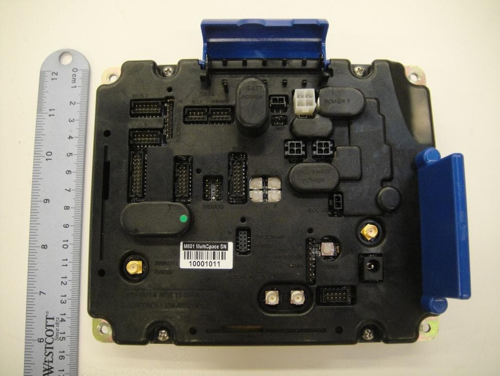
SGWIPS2010M800
Mar 24, 2014Multiple Space Parking Meter Controller Module
Equipment Class
DXX - Part 15 Low Power Communication Device TransmitterSGWIPS2006SSPM
Oct 28, 2013Parking Meter with data collection
Equipment Class
DXX - Part 15 Low Power Communication Device Transmitter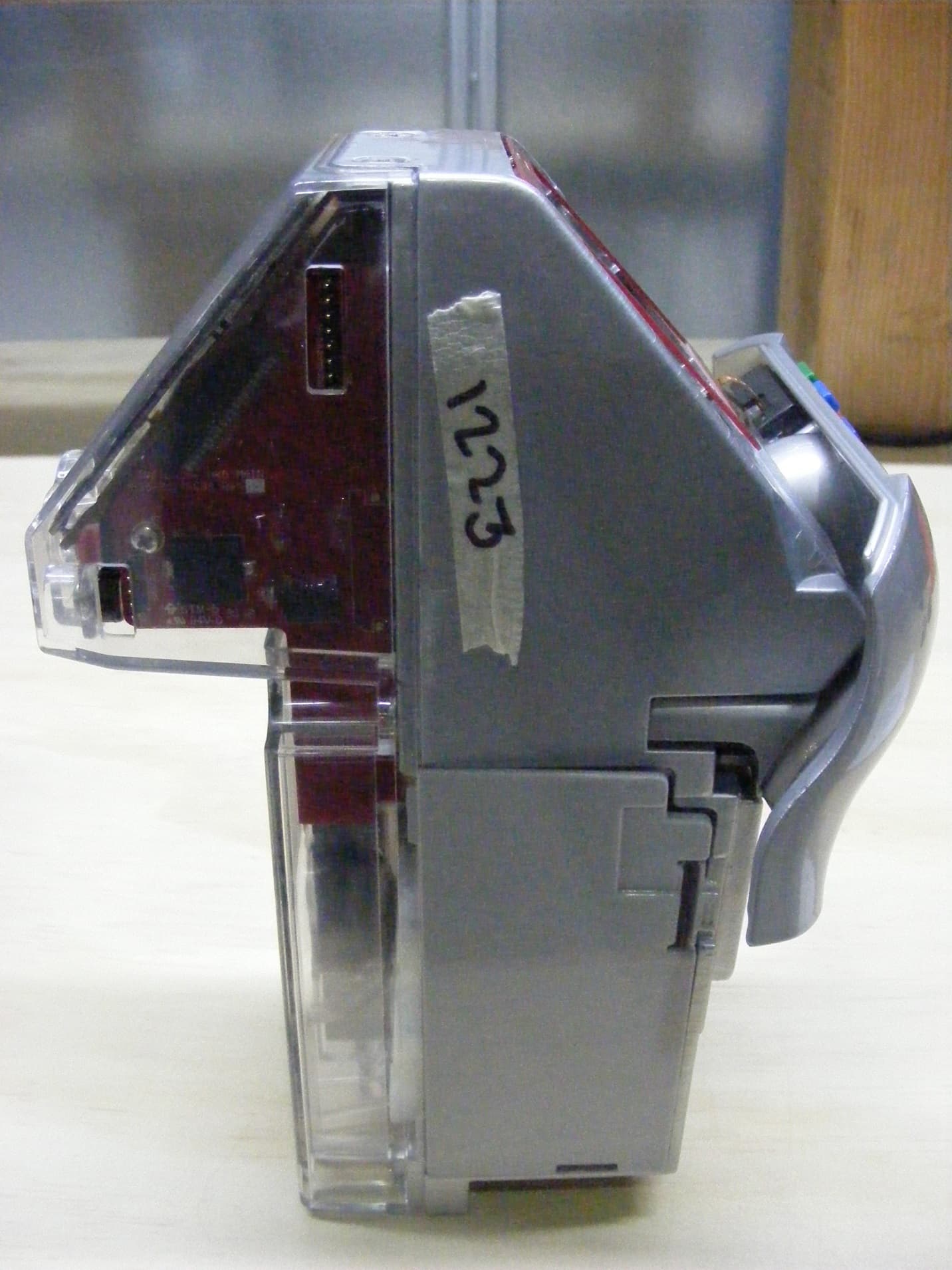
SGWIPS2007SSPM
Apr 04, 2013Parking Meter with Data Collection
Equipment Class
DXX - Part 15 Low Power Communication Device Transmitter