SGWIPS2010M800Multiple Space Parking Meter Controller Module
IPS Group Inc.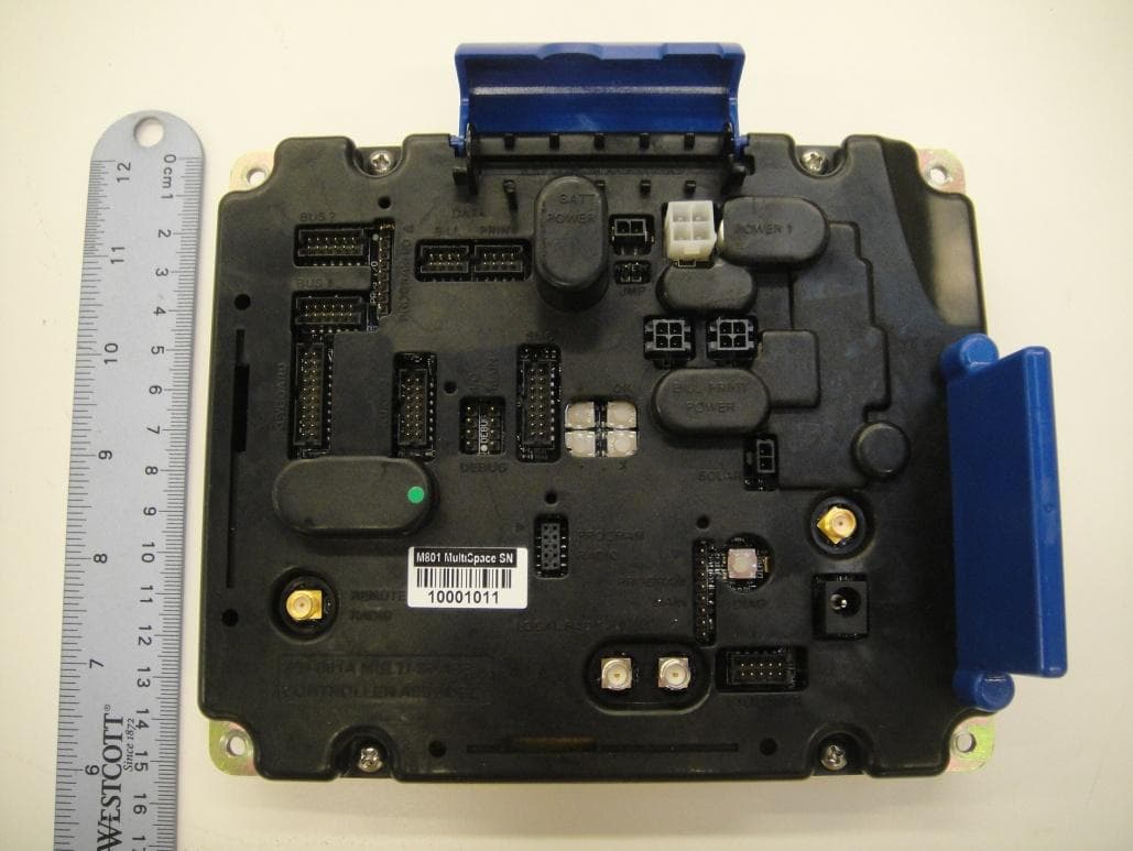
Click to zoom
Application Details
- Equipment Class
- DXX - Part 15 Low Power Communication Device Transmitter
- Date of Grant
- Mar 24, 2014
- Application Purpose
- Original Equipment
- Date of Application
- Mar 24, 2014
- Equipment Note
- Multiple Space Parking Meter Controller Module
- Frequency Range
- 13.56000000 - 13.56000000
- Company
- IPS Group Inc.
- Country
- United States
Documents & Files
Document Text
Text extracted from the exhibit documents filed with the FCC. Open a document above to read the original.
Users Manual
Technical Overview IPS Multi Space Parking Meter Controller Module (MSCM) RF Exposure Rules and Regulations: The system antenna(s) used for this transmitter must be installed to provide a separation distance of at least 20 cm from all the persons and must not be co-located or operating in conjunction with any other antenna or transmitter, except in accordance with FCC and Industry Canada multi-transmitter product procedures. The system antenna(s) used for this module must not exceed 10dBi (CDMA BC0) and 9.31dBi (CDMA BC1) for mobile and fixed operating configurations. Users and installers must be provided with antenna installation instructions and transmitter operating conditions for satisfying RF exposure compliance. The enclosed hardware device complies with Part 15 of the FCC Rules. Operation is subject to the following two conditions: (1) This device may not cause harmful interference, and (2) This device must accept any interference received including interference that may cause undesired operation. Warning (Part 15.21) Changes or modifications not expressly approved by IPS Group, Inc. could void the user’s authority to operate the equipment. Manufacturer is not responsible for any radio or TV interference caused by unauthorized modifications to this equipment. Compliance Statement (Part 15.105(b)) This equipment has been tested and found to comply with the limits for a Class B digital device, pursuant to Part 15 of the FCC Rules. These limits are designed to provide reasonable protection against harmful interference in a residential installation. This equipment generates, uses and can radiate radio frequency energy and, if not installed and used in accordance with the instructions, may cause harmful interference to radio communications. However, there is no guarantee that interference will not occur in a particular installation. If this equipment does cause harmful interference to radio or television reception, which can be determined by turning the equipment off and on, the user is encouraged to try to correct the interference by one or more of the following measures: • Reorient or relocate the receiving antenna • Increase the separation between the equipment and receiver • Connect the equipment into an outlet on a circuit different from that to which the receiver is connected • Consult the dealer or an experienced radio/TV technician for help Industry Canada (IC) regulatory information This device complies with Industry Canada license-exempt RSS standard(s). Operation is subject to the following two conditions: (1) this device may not cause interference, and (2) this device must accept any interference, including interference that may cause undesired operation of the device. Le présent appareil est conforme aux CNR d'Industrie Canada applicables aux appareils radio exempts de licence. L'exploitation est autorisée aux deux conditions suivantes : (1) l'appareil ne doit pas produire de brouillage, et (2) l'utilisateur de l'appareil doit accepter tout brouillage radioélectrique subi, même si le brouillage est susceptible d'en compromettre le fonctionnement. Class B digital device notice This Class B digital apparatus complies with Canadian ICES-003, RSS-Gen and RSS-210. Cet appareil numérique de la classe B est conforme à la norme NMB-003, CNR-Gen et CNR-210 du Canada. IPS GROUP INC November 2013 “To meet the host device labelling requirements, any host equipment incorporating the M800 module must include the FCC ID/IC certification number on the host as follows: Contains FCC ID: SGWIPS2010M800 Contains IC: 11583A-IPS2010M800 Contains FCC ID: RI7UE910NA Contains IC: 5131A-5131A-UE910NA” IPS MSCM Overview Module Description This controller module is intended to be used across a number of IPS Multi Space Parking Meter platforms. These platforms include IPS designed multi space parking terminals as well as a number of existing designs that can be upgraded and retrofitted with this IPS technology. Parking terminals equipped with the MSCM may be configured as Pay and Display, Pay by Space, Pay by Plate and other configurations. The MSCM consist of a large LCD display and a controller section enclosed in a protective mechanical housing. The controller PCBA supports a number of integrated features and interfaces to a number of optional peripheral units. 1 MSCM Rear View Top Level Block Diagram Integrated Features and Interfaces Solar energy harvesting controller. 13.8V battery charger for external 12 VRLA battery. Low voltage supplies for internal use, 5V, 12V and 24V power supplies for external peripherals. Three MSP430 Mixed Signal Microcontrollers 4-way key pad diagnostic keypad Beeper for audible feedback GSM / CDMA Transceiver module for linkup to IPS servers C1190 Low Power 315/433/868/915 MHz ISM/SRD bands Transceiver for vehicle sensors, Coin Canister, etc. TRF7960RHBR 13.56-MHZ RFID Reader System Graphic LCD with controlled backlight Secondary low Voltage energy storage for backup and support* Smart Card Interface IPS Coin Validator Interface A 6x6 Keypad matrix for various keypad configurations. Two RS232 interfaces for Printers, Bank Note Acceptors, etc. 14 pin I/O connector for various sensors Two 10-way Multi Drop Bus connectors for communication between controller and peripherals such as coin handling units, down light and other controllers. Theory of operation Power Management Solar energy is the standard power source for IPS Multi Space Parking Meters. Electrical energy is derived from high efficiency solar panels. This input energy is converted by the MSCM to levels suitable charging and maintaining an external 12V valve regulated lead acid (VRLA or sealed) battery system which in turn supplies power for internal power backup, internal circuits and external peripherals. Long term power autonomy is achieved by switching systems off when not in use and by storing surplus energy in a high capacity VRLA battery. An average of one hour of …
Text truncated - open the document above for the full version.
Cover Letter(s)
Date (02/26/2014) TUV SUD BABT TCB Octagon House, Segensworth Road, Fareham, Hampshire, PO15 5RL Dear Sir or Madam, We, IPS Group, Inc. 5601 Oberlin Drive San Diego,CA 92121 (858) 404-0607, i.e. applicant, hereby authorize TUV SUD America, Inc. 10040 Mesa Rim Rd. San Diego,CA 92121 (858) 678-1400 to act as our agent in all matters relating to applications for equipment authorization, including the signing of all documents relating to these matters. This authorization expires on August 01, 2014. Sincerely, Company Officer: Gary Thomas Telephone Number: 858-768-2401 Email: [email protected]
Cover Letter(s)
Date 02/26/2014 TUV SUD BABT TCB Octagon House, Segensworth Road, Fareham, Hampshire, PO15 5RL Confidentiality Request FCC ID: SGWIPS2010M800 Pursuant to Sections 0.457(d)(1)(ii) and 0.459 of the Commission’s Rules, IPS Group, Inc. hereby requests permanent confidential treatment of information accompanying this application as outlined below: Common exhibits for which confidentiality is requested are: Schematics Bill of Materials/Parts List Block Diagrams Theory of Operation IPS Group, Inc. also hereby requests short-term confidential treatment of information accompanying this application as outlined below for a period of 180 days: Common exhibits for which short-term confidentiality is requested are: Internal Photos External Photos User Manual Test Set-up Photographs The above materials contain trade secrets and proprietary information not customarily released to the public. The public disclosure of these matters might be harmful to the Applicant and provide unjustified benefits to its competitors. The Applicant understands that pursuant to Rule 0.457(d)(1)(ii), disclosure of this Application and all accompanying materials will not be made before the date of the Grant for this Application. Yours sincerely, Company Officer: Gary Thomas Telephone Number: 858-768-2401 Email: [email protected]
Cover Letter(s)
Date (02/24/2014) TUV SUD BABT TCB Octagon House, Segensworth Road, Fareham, Hampshire, PO15 5RL DECLARATION OF CONFORMITY Attestation For FCC Part 15B FCC ID: SGWIPS2010M800 IC: 11583A-IPS2010M800 We The under Signed Company IPS Group Inc. Address, City 5601 Oberlin Drive, San Diego 92121 Country San Diego Phone number 858-768-2401 ext.211 Fax number 858-404-0603 E-mail [email protected] Certify and declare under our sole responsibility that the following equipment: Product Description / Supplementary Info Multiple Space Parking Meter Controller Module Manufacturer IPS Group Inc. Brand Multi-Space Parking Model Type / Reference / Variants M800 It Compliant with the FCC part 15B requirements for Class B Computer Peripheral authorization requirements. Sincerely, Company Officer: Gary Thomas Telephone Number: 858-768-2401 Email: [email protected]
Cover Letter(s)
Date 02/26/2014 TUV SUD BABT TCB Octagon House, Segensworth Road, Fareham, Hampshire, PO15 5RL Dear Sir/Madam, RE: Modular Approval Request for Model: M800 FCC ID: SGWIPS2010M800 The following attestation addresses the requirements to support modular approval: Modular approval requirement Yes No * (a) The radio elements must have the radio frequency circuitry shielded. Physical components and tuning capacitor(s) may be located external to the shield, but must be on the module assembly X (b) The module must have buffered modulation/data inputs to ensure that the device will comply with Part 15 requirements with any type of input signal X (c) The module must contain power supply regulation on the module X (d) The module must contain a permanently attached antenna, or contain a unique antenna connector, and be marketed and operated only with specific antenna(s), per Sections 15.203, 15.204(b), 15.204(c), 15.212(a), 2.929(b) X (e) The module must demonstrate compliance in a stand-alone configuration X (f) The module must be labelled with its permanently affixed FCC ID label, or use an electronic display (See KDB Publication 784748 about labelling requirements) X (g) The module must comply with all specific rules applicable to the transmitter. The grantee must provide comprehensive instructions to explain compliance requirements X (h) The module must comply with RF exposure requirements X * Please provide a detailed explanation if the answer is “No.” Yours sincerely, Name: Gary Thomas Title: Sr. RF Design Engineer
External Photos
FCC ID: SGWIPS2010M800 IC: 11583A-IPS2010M800 Report No.: SC1401258 Page 1 of 2 FCC ID: SGWIPS2010M800 IC: 11583A-IPS2010M800 Report No.: SC1401258 Page 2 of 2
ID Label/Location Info
FCC ID: SGWIPS2010M800 IC: 11583A-IPS2010M800 Report No.: SC1401258 Page 1 of 2 FCC ID: SGWIPS2010M800 IC: 11583A-IPS2010M800 Report No.: SC1401258 Page 2 of 2 Example Label location
Internal Photos
FCC ID: SGWIPS2010M800 IC: 11583A-IPS2010M800 Report No.: SC1401258 Page 1 of 5 FCC ID: SGWIPS2010M800 IC: 11583A-IPS2010M800 Report No.: SC1401258 Page 2 of 5 FCC ID: SGWIPS2010M800 IC: 11583A-IPS2010M800 Report No.: SC1401258 Page 3 of 5 FCC ID: SGWIPS2010M800 IC: 11583A-IPS2010M800 Report No.: SC1401258 Page 4 of 5 FCC ID: SGWIPS2010M800 IC: 11583A-IPS2010M800 Report No.: SC1401258 Page 5 of 5
RF Exposure Info
TÜV SÜD AMERICA INC 10040 Mesa Rim Road San Diego, CA 92121-2912 Phone: 858 678 1400 FAX: 858 546 0364 March 19, 2014 TUV SUD BABT Octagon House, Concorde Way Segensworth Rd N, Fareham PO15 5RL Attention: Director of Certification RE: Prediction of MPE limit at a given distance as per KDB 447498 D01 Mobile Portable RF Exposure V04 using a SMA-Female (rubber pad) with 0dBi gain antenna. FCC ID: SGWIPS2010M800 IC: 11583A-IPS2010M800 Equation from page 18 of OET Bulletin 65, Edition 97-01 where: S = power density P = power input to the antenna G = power gain of the antenna in the direction of interest relative to isotropic R = distance to the center of radiation of the antenna ISM/SRD 400MHz Band Transceiver: Maximum peak output power at antenna input terminal: -43.73 (dBm) Maximum peak output power at antenna input terminal: 0.00 (mW) Antenna gain(typical): 0 (dBi) Maximum antenna gain: 1.000 (numeric) Prediction distance: 20 (cm) Sourse Based Time Average Duty Cycle: 100 (%) Prediction frequency: 430 (MHz) MPE limit for uncontrolled exposure at prediction frequency: 0.28666667 (mW/cm 2 ) Power density at prediction frequency: 0.000000008 (mW/cm 2 ) Power density at prediction frequency: 0.00000008 (W/m 2 ) Margin of Compliance: -75.32 (dB) Sincerely, Alex Chang Name Authorized Signatory Title: EMC/Wireless Test Engineer
RF Exposure Info
TÜV SÜD AMERICA INC 10040 Mesa Rim Road San Diego, CA 92121-2912 Phone: 858 678 1400 FAX: 858 546 0364 March 14, 2014 TUV SUD BABT Octagon House, Concorde Way Segensworth Rd N, Fareham PO15 5RL Attention: Director of Certification RE: Prediction of MPE limit at a given distance as per KDB 447498 D01 Mobile Portable RF Exposure V04 using a PIFA (Planar Inverted F-Antenna) 0dBi trace antenna. FCC ID: SGWIPS2010M800 IC: 11583A-IPS2010M800 1. Mobile MPE Calculation Summary using a 20cm separation distance: Mode Output Power Power Density (mW/m 2 ) RFID -79.33 dBm 0.000000000002 GPRS 850 29.79 dBm 0.3088 EGPRS 850 26.29 dBm 0.1380 WCDMA (Band V) 24.47 dBm 0.0970 GPRS 1900 23.28 dBm 0.0868 EGPRS 1900 21.88 dBm 0.0629 WCDMA (Band II) 23.70 dBm 0.0957 2. Co-Located Transmitters transmission table: Transmitter type Transmitter type that can transmit at the same time RFID GSM GSM RFID 3. Simultaneous Transmission MPE (worst-case): Transmitter type MPE (mw/cm 2 ) Limit (mW/cm 2 ) MPE ratio (MPE/Limit) RFID 0.000000000002 0.978933335 0.000000000002 GPRS 850 0.3088 1.0 0.3088 Sum of the ratios (should be <1.0) 0.308800000002 TÜV SÜD AMERICA INC 10040 Mesa Rim Road San Diego, CA 92121-2912 Phone: 858 678 1400 FAX: 858 546 0364 4. Mobile MPE Calculation using a 20cm separation distance (RFID): Using Power Density formula: where: S = power density P = power input to the antenna G = power gain of the antenna in the direction of interest relative to isotropic R = distance to the center of radiation of the antenna Maximum peak output power at antenna input terminal: -79.33 (dBm) Maximum peak output power at antenna input terminal: 0.00 (mW) Antenna gain(typical): 0 (dBi) Maximum antenna gain: 1.000 (numeric) Prediction distance: 20 (cm) Sourse Based Time Average Duty Cycle: 100 (%) Prediction frequency: 13.56 (MHz) MPE limit for uncontrolled exposure at prediction frequency: 0.978933335 (mW/cm 2 ) Power density at prediction frequency: 0.00000000000232 (mW/cm 2 ) Power density at prediction frequency: 0.00000000002321 (W/m 2 ) Margin of Compliance: -116.25 (dB) TÜV SÜD AMERICA INC 10040 Mesa Rim Road San Diego, CA 92121-2912 Phone: 858 678 1400 FAX: 858 546 0364 5. Mobile MPE Calculation using a 20cm separation distance (GPRS 850): Maximum peak output power at antenna input terminal: 29.79 (dBm) Maximum peak output power at antenna input terminal: 952.80 (mW) Antenna gain(typical): 2.12 (dBi) Maximum antenna gain: 1.629 (numeric) Prediction distance: 20 (cm) Sourse Based Time Average Duty Cycle: 100 (%) Prediction frequency: 848.8 (MHz) MPE limit for uncontrolled exposure at prediction frequency: 0.56586667 (mW/cm 2 ) Power density at prediction frequency: 0.3088 (mW/cm 2 ) Power density at prediction frequency: 3.088 (W/m 2 ) Margin of Compliance: -2.63 (dB) Sincerely, Alex Chang Name Authorized Signatory Title: EMC/Wireless Test Engineer
Test Report
Report No. SC1401258B March 2014 America Report On Radio Testing of the IPS Group Inc. MSCM Multiple Space Parking Meter Controller Module FCC Part 15 Subpart C §15.225 IC RSS-210 Issue 8 December 2010 FCC ID SGWIPS2010M800 IC: 11583A-IPS2010M800 Report No. SC1401258B Page 2 of 35 TÜV SÜD AMERICA INC 10040 Mesa Rim Road San Diego, CA 92121-2912 Phone: 858 678 1400 FAX: 858 546 0364 REPORT ON TEST REPORT NUMBER PREPARED FOR Radio Testing of the IPS Group Inc. Multiple Space Parking Meter Controller Module SC1401258B IPS Group Inc. 5601 Oberlin Drive San Diego, CA 92121 CONTACT PERSON Gary Thomas RF Engineer (858) 768-2401 ext. 211 [email protected] PREPARED BY Alex Chang Name Authorized Signatory Title: EMC/Wireless Test Engineer APPROVED BY Chip R. Fleury Name Authorized Signatory Title: West Coast EMC Manager DATED March 04, 2014 FCC ID SGWIPS2010M800 IC: 11583A-IPS2010M800 Report No. SC1401258B Page 3 of 35 TÜV SÜD AMERICA INC 10040 Mesa Rim Road San Diego, CA 92121-2912 Phone: 858 678 1400 FAX: 858 546 0364 Revision History SC1401258B IPS Group Inc. MSCM Multiple Space Parking Meter Controller Module DATE OLD REVISION NEW REVISION REASON PAGES AFFECTED APPROVED BY 03/04/2014 Initial Release Chip R. Fleury FCC ID SGWIPS2010M800 IC: 11583A-IPS2010M800 Report No. SC1401258B Page 4 of 35 TÜV SÜD AMERICA INC 10040 Mesa Rim Road San Diego, CA 92121-2912 Phone: 858 678 1400 FAX: 858 546 0364 CONTENTS Section Page No 1 REPORT SUMMARY ............................................................................................................................... 5 1.1 Introduction ................................................................................................................................................ 6 1.2 Brief Summary Of Results ........................................................................................................................... 7 1.3 Product Information ................................................................................................................................... 8 1.4 EUT Test Configuration ............................................................................................................................. 10 1.5 Deviations From The Standard ................................................................................................................. 11 1.6 Modification Record ................................................................................................................................. 11 1.7 Test Methodology ..................................................................................................................................... 11 1.8 Test Facility Location ................................................................................................................................. 11 1.9 Test Facility Registration ........................................................................................................................... 11 2 TEST DETAILS ...................................................................................................................................... 13 2.1 Occupied Bandwidth ................................................................................................................................. 14 2.2 In Band Emissions ..................................................................................................................................... 16 2.3 Out Of Band Emissions .............................................................................................................................. 19 2.4 Frequency Tolerance ................................................................................................................................ 23 2.5 Receiver Spurious Emissions ..................................................................................................................... 25 3 TEST EQUIPMENT USED ...................................................................................................................... 28 3.1 Test Equipment Used ................................................................................................................................ 29 3.2 Measurement Uncertainty ....................................................................................................................... 30 4 DIAGRAM OF TEST SETUP ................................................................................................................... 31 4.1 Test Setup Diagram ................................................................................................................................... 32 5 ACCREDITATION, DISCLAIMERS AND COPYRIGHT ............................................................................... 34 5.1 Accreditation, Disclaimers And Copyright ................................................................................................ 35 FCC ID SGWIPS2010M800 IC: 11583A-IPS2010M800 Report No. SC1401258B Page 5 of 35 TÜV SÜD AMERICA INC 10040 Mesa Rim Road San Diego, CA 92121-2912 Phone: 858 678 1400 FAX: 858 546 0364 SECTION 1 REPORT SUMMARY Radio Testing of the IPS Group Inc. Multiple Space Parking Meter Controller Module FCC ID SGWIPS2010M800 IC: 11583A-IPS2010M800 Report No. SC1401258B Page 6 of 35 TÜV SÜD AMERICA INC 10040 Mesa Rim Road San Diego, CA 92121-2912 Phone: 858 678 1400 FAX: 858 546 0364 1.1 INTRODUCTION The information contained in this report is intended to show verification of the IPS Group Inc. Multiple Space Parking Meter Controller Module to the requirements of FCC Part 15 Subpart C §15.225 and IC RSS-210 Issue 8 December 2010. Objective To perform Radio Testing to determine the Equipment Under Test's (EUT’s) compliance with the Test Specification, for the series of tests carried out. Manufacturer IPS Group Inc. Model Number(s) M800 FCC ID Number SGWIPS2010M800 FCC Classification Low Power Communications Device Transmitter (DXX) IC …
Text truncated - open the document above for the full version.
Test Setup Photos
FCC ID: SGWIPS2010M800 IC: 11583A-IPS2010M800 Report No.: SC1401258 Page 1 of 8 RFID and ISM/SRD Radiated Emission Measurement Below 1GHz (Front) FCC ID: SGWIPS2010M800 IC: 11583A-IPS2010M800 Report No.: SC1401258 Page 2 of 8 RFID and ISM/SRD Radiated Emission Measurement Below 1GHz (Back) FCC ID: SGWIPS2010M800 IC: 11583A-IPS2010M800 Report No.: SC1401258 Page 3 of 8 RFID Radiated Emission Measurement 9kHz to 30MHz (Front) FCC ID: SGWIPS2010M800 IC: 11583A-IPS2010M800 Report No.: SC1401258 Page 4 of 8 RFID Radiated Emission Measurement 9kHz to 30MHz (Back) FCC ID: SGWIPS2010M800 IC: 11583A-IPS2010M800 Report No.: SC1401258 Page 5 of 8 ISM/SRD Radiated Emission Measurement Above 1GHz (Front) FCC ID: SGWIPS2010M800 IC: 11583A-IPS2010M800 Report No.: SC1401258 Page 6 of 8 ISM/SRD Radiated Emission Measurement Above 1GHz (Back) FCC ID: SGWIPS2010M800 IC: 11583A-IPS2010M800 Report No.: SC1401258 Page 7 of 8 RFID Frequency Tolerance Measurement FCC ID: SGWIPS2010M800 IC: 11583A-IPS2010M800 Report No.: SC1401258 Page 8 of 8 ISM/SRD Conducted Antenna Port Bandwidth Measurement
Contact Information
Applicant
Hugo Farias(Technical Project Manager)
Test Firm
TUV SUD America Inc.Mac Elliott
Technical Specifications
| # | Rule Parts | Frequency Range | Power Output |
|---|---|---|---|
| 2 | 15C | 13.56 MHz - 13.56 MHz | - |
Other Applications from IPS Group Inc.

SGWIPS2013VS
Jul 14, 2014Vehicle Detection Sensor
Equipment Class
DXX - Part 15 Low Power Communication Device Transmitter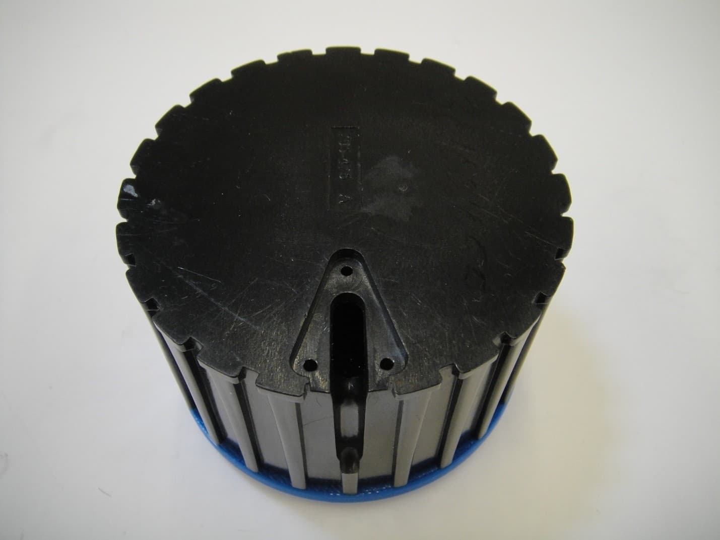
SGWIPS2007VS
Apr 10, 2014Vehicle Detection Sensor
Equipment Class
DXX - Part 15 Low Power Communication Device TransmitterSGWIPS2006SSPM
Oct 28, 2013Parking Meter with data collection
Equipment Class
DXX - Part 15 Low Power Communication Device Transmitter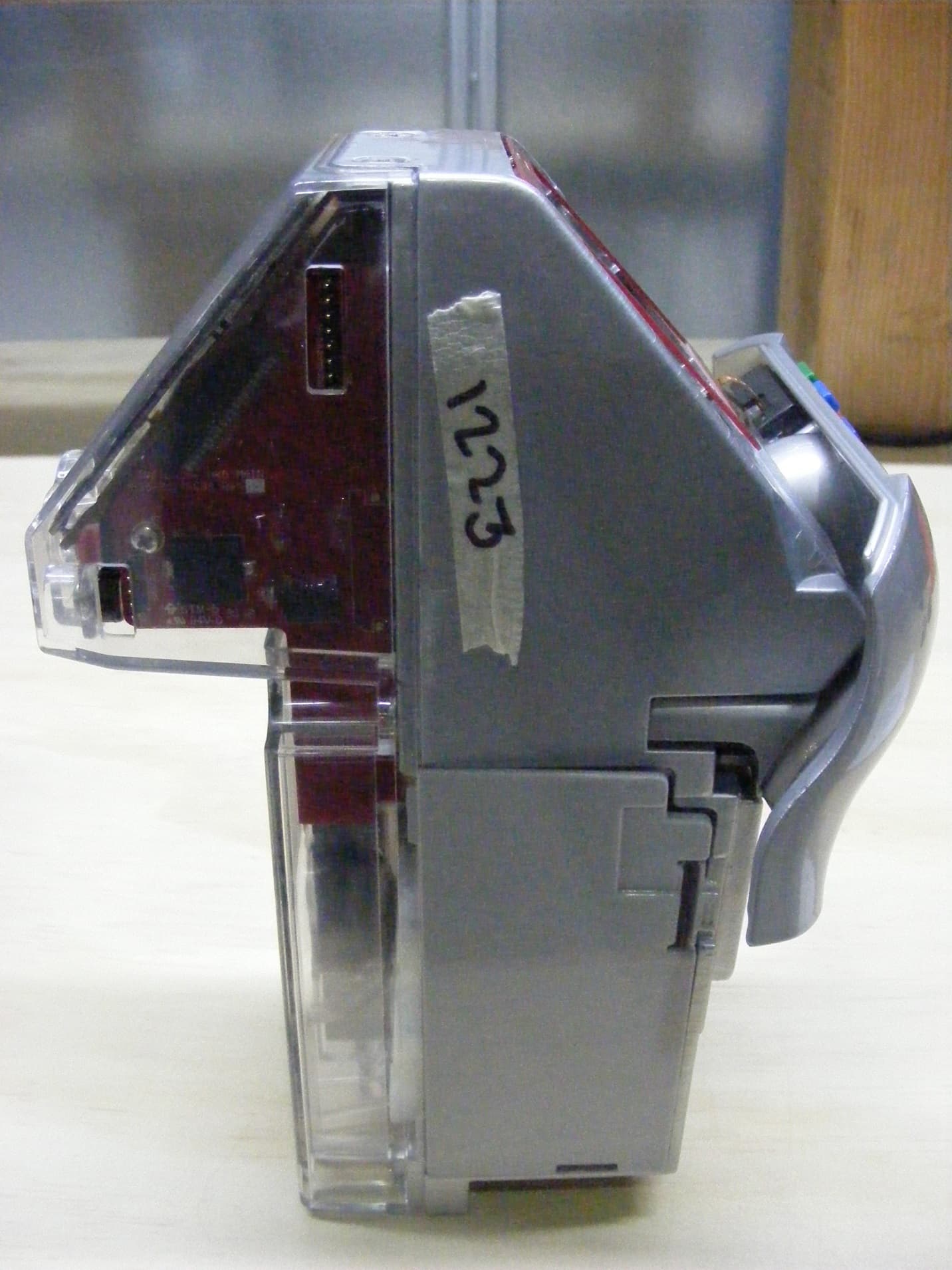
SGWIPS2007SSPM
Apr 04, 2013Parking Meter with Data Collection
Equipment Class
DXX - Part 15 Low Power Communication Device Transmitter