SIO-NSRH100NSR.H100 (naviPlay Stereo Remote)
TEN Technology, Inc.Application Details
- Equipment Class
- DTS - Digital Transmission System
- Date of Grant
- Dec 21, 2004
- Application Purpose
- Original Equipment
- Date of Application
- Dec 21, 2004
- Equipment Note
- NSR.H100 (naviPlay Stereo Remote)
- Frequency Range
- 2402.00000000 - 2480.00000000
- Company
- TEN Technology, Inc.
- Country
- United States
Documents & Files
Document Text
Text extracted from the exhibit documents filed with the FCC. Open a document above to read the original.
Cover Letter(s)
Northwest EMC TCB Compliance Opinion Rev. 9/15/03 Smrm0002 Information about the Applicant Company Name TEN Technology, Inc. Grantee Thomas Hsiu Address 130 Katherien Court, #4 City, State, Zip San Antonio, TX 78209 Job Number SMRM0002 Model naviPlay Stereo Remote NSR.H100 FCC ID SIO-NSRH100 Agent Smart Modular Technologies, Inc. Approval Type Original Equipment Class DTS Digital Transmission System Rule Part 15.247 BlueTooth Overview The radio section of the Bluetooth naviPlay Stereo Remote, model NSR.H100 consists of a Power Class 2 (2.5 mW max.) Bluetooth radio with an internal antenna. It is fully compliant with the FCC Part 15 standard and Bluetooth 1.2 specifications. Recommendation All items have been resolved and completed to my satisfaction; therefore I recommend this application for approval. Signature 12/20/2004 Dave Tolman, TCB Committee Northwest EMC TCB Compliance Opinion Rev. 9/15/03 Smrm0002 Findings Opinions Specification Requirements Description 47 Cfr 2.1033(b)(3) Installation guide, operating instructions,user manual Opinion The device meets the requirements of the rule. Discussion The client has provided the necessary exhibit. Reference User Manual.pdf Specification Requirements Description 47 Cfr 2.1033(b)(4) Operational description Opinion The device meets the requirements of the rule. Discussion The client has provided the necessary exhibit. Reference Operational Description.pdf Specification Requirements Description 47 Cfr 2.1033(b)(5) Frequency block diagram Opinion The device meets the requirements of the rule. Discussion The client has provided the necessary exhibit. Reference Block Diagram.pdf Specification Requirements Description 47 Cfr 2.1033(b)(6) Schematic diagram Opinion The device meets the requirements of the rule. Discussion The client has provided the necessary exhibit. Reference Schematics.pdf Specification Requirements Description 47 Cfr 2.1033(b)(7) Internal and external photos Opinion The device meets the requirements of the rule. Discussion The client has provided the necessary exhibit. Reference Internal Photos.pdf, External Photos.pdf Specification Requirements Description 47 Cfr 2.1033(b)(6) Conversions showing how the test results were achieved Opinion The device meets the requirements of the rule. Discussion The client has provided the necessary exhibit. Reference Schematics.pdf Northwest EMC TCB Compliance Opinion Rev. 9/15/03 Smrm0002 Specification Requirements Description Required Exhibit Test Setup Photo Exhibit Opinion The device meets the requirements of the rule. Discussion The client has provided the necessary exhibit. Reference Technical Report_7LAY0028.pdf.pdf Specification Requirements Description 47 Cfr 1.1307(b),2.1091,2.1093 RF Exposure Hazzard Opinion The device meets the requirements of the rule. Discussion The client has provided the necessary exhibit. Reference Technical Report_7LAY0028.pdf Specification Requirements Description 47 Cfr 15.19 Labeling Opinion The device meets the requirements of the rule. Discussion The client has provided the necessary exhibit. Reference User Manual.pdf, Label.pdf Specification Requirements Description 47 Cfr 15.21 Information for user Opinion The device meets the requirements of the rule. Discussion The client has provided the necessary exhibit. Reference User Manual.pdf Specification Requirements Description 47 Cfr 15.27 Special accessories Opinion The device meets the requirements of the rule. Discussion The client has provided the necessary exhibit. Reference Technical Report_7LAY0028.pdf Specification Requirements Description 47 Cfr 15.33 Frequency range of tests Opinion The device meets the requirements of the rule. Discussion The client has provided the necessary exhibit. Reference Technical Report_7LAY0028.pdf Specification Requirements Description 47 Cfr 15.35 Measurement detectors Opinion The device meets the requirements of the rule. Discussion The client has provided the necessary exhibit. Reference Technical Report_7LAY0028.pdf Northwest EMC TCB Compliance Opinion Rev. 9/15/03 Smrm0002 Specification Requirements Description ANSI C63.4 EUT Ports All EUT ports populated,emissions maximized,Antenna height adjusted Opinion The device meets the requirements of the rule. Discussion The client has provided the necessary exhibit. Reference Technical Report_7LAY0028.pdf Specification Requirements Description 47 Cfr 15.203 Antenna Requirements Opinion The device meets the requirements of the rule. Discussion The client has provided the necessary exhibit. Reference Technical Report_7LAY0028.pdf Specification Requirements Description 47 Cfr 15.205 Restricted bands Opinion The device meets the requirements of the rule. Discussion The client has provided the necessary exhibit. Reference Technical Report_7LAY0028.pdf Specification Requirements Description 47 Cfr 15.207 Power line Conducted emissions Opinion The device meets the requirements of the rule. Discussion The client has provided the necessary exhibit. Reference Technical Report_7LAY0028.pdf Specification Requirements Description 47 Cfr 15.209 Spurious Emissions Opinion The device meets the requirements of the rule. Discussion The client has provided the necessary exhibit. Reference Technical Report_7LAY0028.pdf Specification Requirements Description 47 Cfr 15.247(a) Occupied Bandwidth Opinion The device meets the requirements of the rule. Discussion The client has provided the necessary exhibit. Reference Technical Report_7LAY0028.pdf Specification Requirements Description 47 Cfr 15.247(b) Output Power Opinion The device meets the requirements of the rule. Discussion The client has provided the necessary exhibit. Reference Technical Report_7LAY0028.pdf Northwest EMC TCB Compliance Opinion Rev. 9/15/03 Smrm0002 Specification Requirements Description 47 Cfr 14.247(c) Band Edge Compliance Opinion The device meets the requirements of the rule. Discussion The client has provided the necessary exhibit. Reference Technical Report_7LAY0028…
Text truncated - open the document above for the full version.
Cover Letter(s)
Corporate Headquarters: P.O.Box 1757,Fremont,CA 94538,USA •Tel:(510)623-1231 •Fax:(510)623-1434 •Email:[email protected] Asia/Pacific: Plot 18,Lrg Jelawat 4,Kawasan Perindustrian Seberang Jaya 13700,Prai,Penang,Malaysia •Tel:+604-3992909 •Fax:+604-3992903 Attn. Certification Manager NORTHWEST EMC 22975 Evergreen Pkwy, Suite 400 97124 Hillsboro, Oregon December 9, 2004 I would like to apply for an original FCC certification of the following product on behalf of TEN Technology, Inc.: Product name: Bluetooth naviPlay Stereo Remote Model number: NSR.H100 FCC ID : SIO-NSRH100 FRN number: 0011002722 The radio section of the Bluetooth naviPlay Stereo Remote, model NSR.H100 consists of a Power Class 2 (2.5 mW max.) Bluetooth radio with an internal antenna. It is fully compliant with the FCC Part 15 standard and Bluetooth 1.2 specifications. The following documents in PDF format (version 5.0) are included: NSR.H100.NorthwestEMC.FCC.cover.letter.doc” (this letter with hyperlinks to documents) TCB415 Contract TCB415 Schedules A and B TCB410 Application for Certification Agent Authorization Confidentiality Request FCC ID Label and Location External and Internal Photos EUT Information Operational Description Block Diagram Schematic Motherboard ASY90202 Schematic Control Board ASY90189 Antenna Info GigaRufa 3030A5645-01 User Guide - Draft RF Exposure Calculations FCC Test Report Please do contact me should you have any questions or need additional documentation. Best regards, Lubos Honzik Regulatory Compliance Engineer SMART Modular Technologies, Inc. 130 Katherine Court #4 San Antonio, TX 78209, USA Tel: (210) 824-4873 Email: [email protected]
Cover Letter(s)
Corporate Headquarters: P.O.Box 1757,Fremont,CA 94538,USA •Tel:(510)623-1231 •Fax:(510)623-1434 •Email:[email protected] Asia/Pacific: Plot 18,Lrg Jelawat 4,Kawasan Perindustrian Seberang Jaya 13700,Prai,Penang,Malaysia •Tel:+604-3992909 •Fax:+604-3992903 1 of 1 Attn. Certification Manager NORTHWEST EMC 22975 Evergreen Pkwy, Suite 400 97124 Hillsboro, Oregon December 7, 2004 Subject:Confidentiality Request FCC ID:SIO-NSRH100 I would like to request confidentiality for the block diagram, schematics and operational descrip- tion of the TEN Technology’s Bluetooth naviPlay Stereo Remote, model NSR.H100 . The reason is, TEN Technology, Inc. wants to protect its IP and investments in this new technol- ogy. TEN Technology, Inc. doesn’t want to make the block diagram, schematics and operational description freely available to its competitors. Thank you for your understanding. Best regards, Lubos Honzik Regulatory Compliance Engineer
External Photos
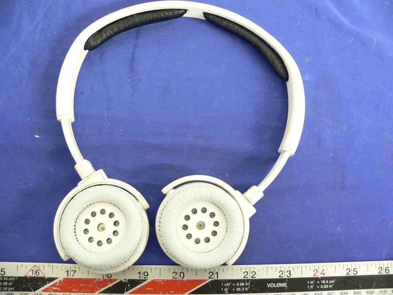
Bluetooth NaviPlay Stereo Remote Model NSR.H100 December 1, 2004 technology Front View Front and Regulatory Label
Operational Description
Product Specification Product Specification Mica 2.4 GHz SMD Antenna Rev : FE010315-G / April 30 2004 Mica 2.4 GHz SMD Antenna 2 (10) 1. FEATURES - Designed for 2.4 GHz applications [Bluetooth TM , WiFi TM (802.11b/g), Zigbee TM , WiMedia TM etc.] - Intended for SMD mounting - Supplied in tape on reel 2. DESCRIPTION - Mobile phones - PDAs - Headsets - Laptops - Medical equipment - Automotive 3. APPLICATION The Mica antenna is intended for use with all 2.4 GHz applications. The antenna requires a groundplane, i.e your device acts as an active part of the antenna and thus demand careful consideration concerning its placement TABLE OF CONTENT 1. Features ......................................................................................................................................................................... 2 2. Description ..................................................................................................................................................................... 2 3. Application ...................................................................................................................................................................... 2 4. Model name .................................................................................................................................................................... 3 5. General data ................................................................................................................................................................... 3 6. Electrical characteristics ................................................................................................................................................. 3 7. Electrical performance .................................................................................................................................................... 4 7.1 Voltage Standing Wave Ratio ............................................................................................................................... 4 7.2 3D-Radiation ........................................................................................................................................................ 4 7.3 Radiation patterns ................................................................................................................................................ 4 8. Antenna Dimensions ....................................................................................................................................................... 5 9. Antenna Foot print .......................................................................................................................................................... 5 10. Electrical interface ........................................................................................................................................................ 6 10.1 Transmission line and matching ......................................................................................................................... 6 10.2 Test board dimensions ....................................................................................................................................... 6 10.3 Test board matching ........................................................................................................................................... 6 11. Soldering ....................................................................................................................................................................... 6 11.1 Recommended soldering conditions ..................................................................................................................... 6 11.2 Leadfree soldering ................................................................................................................................................ 6 12. Reliability ...................................................................................................................................................................... 7 12.1 Temperature and Humidity ................................................................................................................................. 7 12.2 Mechanical ......................................................................................................................................................... 7 12.3 Miscellaneous .................................................................................................................................................... 7 12.4 Judgement standard .......................................................................................................................................... 7 13. Hazardous Material Reguration Conformance .............................................................................................................. 7 14. Application example ...................................................................................................................................................... 8 15. Packaging ..................................................................................................................................................................... 9 15.1 Shelf storage recommendation .......................................................................................................................... 9 15.2 Tape characteristics ........................................................................................................................................... 9 15.3 Reel dimension .................................................................................................................................................. 9 15.4 Box dimension ................................................................................................................................................... 9 15…
Text truncated - open the document above for the full version.
RF Exposure Info
Bluetooth naviPlay Stereo Remote Model NSR.H100 technology Estimate of RF Field Maximum Exposure OET Bulletin 65, Edition 97-1, August 1997 Calculations can be made to predict RF power density levels around typical RF sources. For example, in the case of a single radiating antenna, a prediction for power density in the far-field of the antenna can be made by use of the equation below. This equation is generally accurate in the far-field of an antenna but will over-predict power density in the near field, where it could be used for making a "worst case" or conservative prediction.: where: S = power density (in appropriate units, e.g. mW/cm 2 ) R = distance to the center of radiation of the antenna (appropriate units, e.g., cm) EIRP = equivalent (or effective) isotropically radiated power (in appropriate units, e.g., mW) Power Density Calculations Using Maximum EIRP Value The Bluetooth naviPlay Stereo Remote, model NSR.H100, can classified as a Portable Device. As per 47 CFR §2.1091 Portable Devices have their radiating elements operating 20 cm or less from the body of the user or of a nearby person. FCC power density limit for MPE for General Popula- tion/Uncontrolled Exposure is S max = 1.0 mW/cm 2 (OET Bulletin 65 Supplement C, Edition 97- 01). The maximum EIRP of a Bluetooth Class 2 transmitter is 2.5 mW. The power density at the dis- tance of r = 2.5 cm from the antenna is: The power density of the Bluetooth naviPlay iPod Adapter transmitter at 2.5 cm distance is still 30 times less than the FCC exposure limit for General Population. The maximum power density of 1.0 mW/cm 2 would theoretically be exceeded at a distance of less than 4.5 mm: S EIRP 4πR 2 -------------- = W EIRP 4πr 2 -------------- 2.5 4π2.5 2 × ---------------------- 0.032mW cm 2 ⁄[]=== r EIRP 4πW -------------- 2.5 4π1.0× --------------------0.45cm[]===
Test Report
7Layers for Smart Modular Technologies naviPlay iPod Adapter naviPlay Stereo Remote December 8, 2004 Report No. 7LAY0028 Report Prepared By www.nwemc.com 1-888-EMI-CERT © 2004 Northwest EMC, Inc 22975 NW Evergreen Parkway Suite 400 Hillsboro, Oregon 97124 Certificate of Test Issue Date: December 8, 2004 Smart Modular Technologies Model NIA.S10 naviPlay iPod Adapter Model NSR.H100 naviPlay Stereo Remote Emissions Specification Test Method Pass Fail FCC 15.247(a) Occupied Bandwidth:2004 ANSI C63.4:2003 FCC 15.247(b) Output Power:2004 ANSI C63.4:2003 FCC 15.247(c) Band Edge Compliance:2004 ANSI C63.4:2003 FCC 15.247(c) Spurious Conducted Emissions:2004 ANSI C63.4:2003 FCC 15.247(c) Spurious Radiated Emissions:2004 ANSI C63.4:2003 FCC 15.247(d) Power Spectral Density:2004 ANSI C63.4:2003 FCC 15.207 AC Power Line Conducted Emissions:2004 ANSI C63.4:2003 Modifications made to the product See the Modifications section of this report Test Facility The measurement facilities used to collect the data is located at: Northwest EMC, Inc. 22975 NW Evergreen Parkway, Suite 400; Hillsboro, OR 97124 Phone: (503) 844-4066 Fax: 844-3826 Northwest EMC, Inc. 41 Tesla, Irvine, CA 92618 Phone: (949) 861-8918 Fax: 861-8923 The sites have been fully described in a report filed with and accepted by the FCC (Federal Communications Commission) and Industry Canada. Approved By: Don Facteau, IS Manager This report must not be used to claim product certification, approval, or endorsement by NVLAP, NIST, or any agency of the federal government of the United States of America. Product compliance is the responsibility of the client, therefore the tests and equipment modes of operation represented in this report were agreed upon by the client, prior to testing. This Report may only be duplicated in its entirety. The results of this test pertain only to the sample(s) tested, the specific description is noted in each of the individual sections of the test report supporting this certificate of test. Northwest EMC Revision History Revision 05/05/03 Revision Number Description Date Page Number 00 None Northwest EMC Accreditations and Authorizations Revision 04/01/04 FCC: Accredited by NVLAP for performance of FCC radio, digital, and ISM device testing. Our Open Area Test Sites, certification chambers, and conducted measurement facilities, have been fully described in reports filed with the FCC and accepted by the FCC in letters maintained in our files. Northwest EMC has been accredited by ANSI to ISO / IEC Guide 65 as a product certifier. We have been designated by the FCC as a Telecommunications Certification Body (TCB). This allows Northwest EMC to certify transmitters to FCC specifications in accordance with 47 CFR 2.960 and 2.962. NVLAP: Northwest EMC, Inc. is recognized under the United States Department of Commerce, National Institute of Standards and Technology, National Voluntary Laboratory Accreditation Program for satisfactory compliance with the requirements of ISO/IEC 17025 for Testing Laboratories. The NVLAP accreditation encompasses Electromagnetic Compatibility Testing in accordance with the European Union EMC Directive 89/336/EEC, ANSI C63.4, MIL-STD 461E, DO-160D and SAE J1113. Additionally, Northwest EMC is accredited by NVLAP to perform radio testing in accordance with the European Union R&TTE Directive 1999/5/EEC, the requirements of FCC, and the RSS radio standards for Industry Canada. Accreditation has been granted to Northwest EMC, Inc. under Certificate Numbers: 200629-0, 200630-0, and 200676-0. Industry Canada: Accredited by NVLAP for performance of Industry Canada RSS and ICES testing. Our Open Area Test Sites and certification chambers comply with RSS 212, Issue 1 (Provisional) and have been filed with Industry Canada and accepted. Northwest EMC has been accredited by ANSI to ISO / IEC Guide 65 as a product certifier. We have been designated by NIST and recognized by Industry Canada as a Certification Body (CB) per the APEC Mutual Recognition Arrangement (MRA). This allows Northwest EMC to certify transmitters to Industry Canada technical requirements. CAB: Designated by NIST and validated by the European Commission as a Conformity Assessment Body (CAB) to conduct tests and approve products to the EMC directive and transmitters to the R&TTE directive, as described in the U.S. - EU Mutual Recognition Agreement TÜV Product Service: Included in TUV Product Service Group's Listing of Recognized Laboratories. It qualifies in connection with the TUV Certification after Recognition of Agent's Testing Program for the product categories and/or standards shown in TUV's current Listing of CARAT Laboratories available from TUV. A certificate was issued to represent that this laboratory continues to meet TUV's CARAT Program requirements. Certificate No. USA0401C Northwest EMC Accreditations and Authorizations Revision 04/01/04 TÜV Rheinland: Authorized to carryout EMC tests by order and under supervision of TÜV Rheinland. This authorization is based on "Conditions for EMC- Subcontractors" of November 1992. NEMKO: Assessed and accredited by NEMKO (Norwegian testing and certification body) for European emissions and immunity testing. As a result of NEMKO's laboratory assessment, they will accept test results from Northwest EMC, Inc. for product certification (Authorization No. ELA 119). Technology International: Assessed in accordance with ISO Guide 25 defining the general international requirements for the competence of calibration and testing laboratories and with ITI assessment criteria LACO196. Based upon that assessment Interference Technology International, Ltd., has granted approval for specifications implementing the EU Directive on EMC (89/336/EEC and amendments). The scope of the approval was provided on a Schedule of Assessment supplied with the certificate and is available upon request. Australia/New Zealand: The National Association of Testing Authorities (NATA), Australia has been appointed by the ACA…
Text truncated - open the document above for the full version.
Test Report
BLUETOOTH APPROVALS FCC Procedure Received from Joe Dichoso on 2-15-02 The following exhibit indicates the FCC Spread Spectrum requirements in Section 15.247 for devices meeting the Bluetooth Specifications in the 2.4 GHz band as of February 2001 operating in the USA. The purpose of this exhibit is to help expedite the approval process for Bluetooth devices. This exhibit provides items that vary for each device and also provides a list of items that are common to Bluetooth devices that explains the remaining requirements. The list of common items can be submitted for each application for equipment authorization. This exhibit only specifies requirements in Section 15.247, requirements in other rule Sections for intentional radiators such as in Section 15.203 or 15.207 must be also be addressed. A Bluetooth device is a FHSS transmitter in the data mode and applies as a Hybrid spread spectrum device in the acquisition mode. For each individual device, the following items, 1-7 will vary from one device to another and must be submitted. 1) The occupied bandwidth in Section 15.247(a)(1)(ii). 2) Conducted output power specified in Section 15.247(b)(1). 3) EIRP limit in Section 15.247(b)(3). 4) RF safety requirement in Section 15.247(b)(4) 5) Spurious emission limits in Section 15.247(c). 6) Processing gain and requirements for Hybrids in Section 15.247(f) in the acquisition mode. 7) Power spectral density requirement in Section 15.247(f) in the acquisition mode. For all devices, the following items, 1-12, are common to all Bluetooth devices and will not vary from one device to another. This list can be copied into the filing. 1 Output power and channel separation of a Bluetooth device in the different operating modes: The different operating modes (data-mode, acquisition-mode) of a Bluetooth device don’t influence the output power and the channel spacing. There is only one transmitter which is driven by identical input parameters concerning these two parameters. Only a different hopping sequence will be used. For this reason, the RF parameters in one op-mode is sufficient. 2 Frequency range of a Bluetooth device: The maximum frequency of the device is: 2402 – 2480 MHz. This is according the Bluetooth Core Specification V 1.0B (+ critical errata) for devices which will be operated in the USA. Other frequency ranges ( e.g. for Spain, France, Japan) which are allowed according the Core Specification must not be supported by the device. 3 Co-ordination of the hopping sequence in data mode to avoid simultaneous occupancy by multiple transmitters: Bluetooth units which want to communicate with other units must be organized in a structure called piconet. This piconet consist of max. 8 Bluetooth units. One unit is the master the other seven are the slaves. The master co-ordinates frequency occupation in this piconet for all units. As the master hop sequence is derived from it’s BD address which is unique for every Bluetooth device, additional masters intending to establish new piconets will always use different hop sequences. 4 Example of a hopping sequence in data mode: Example of a 79 hopping sequence in data mode: 40, 21, 44, 23, 42, 53, 46, 55, 48, 33, 52, 35, 50, 65, 54, 67, 56, 37, 60, 39, 58, 69, 62, 71, 64, 25, 68, 27, 66, 57, 70, 59, 72, 29, 76, 31, 74, 61, 78, 63, 01, 41, 05, 43, 03, 73, 07, 75, 09, 45, 13, 47, 11, 77, 15, 00, 64, 49, 66, 53, 68, 02, 70, 06, 01, 51, 03, 55, 05, 04 5 Equally average use of frequencies in data mode and short transmissions: The generation of the hopping sequence in connection mode depends essentially on two input values: 1. LAP/UAP of the master of the connection 2. Internal master clock The LAP (lower address part) are the 24 LSB’s of the 48 BD_ADDRESS. The BD_ADDRESS is an unambiguous number of every Bluetooth unit. The UAP (upper address part) are the 24 MSB’s of the 48 BD_ADDRESS. The internal clock of a Bluetooth unit is derived from a free running clock which is never adjusted and is never turned off. For synchronization with other units, only the offsets are used. It has no relation to the time of the day. Its resolution is at least half the RX/TX slot length of 312.5 μs. The clock has a cycle of about one day (23h30). In most case it is implemented as 28 bit counter. For the deriving of the hopping sequence the entire LAP (24 bits), 4 LSB’s (4 bits) (Input 1) and the 27 MSB’s of the clock (Input 2) are used. With this input values different mathematical procedures (permutations, additions, XOR-operations) are performed to generate the sequence. This will be done at the beginning of every new transmission. Regarding short transmissions, the Bluetooth system has the following behavior: The first connection between the two devices is established, a hopping sequence is generated. For transmitting the wanted data, the complete hopping sequence is not used and the connection ends. The second connection will be established. A new hopping sequence is generated. Due to the fact that the Bluetooth clock has a different value, because the period between the two transmission is longer (and it cannot be shorter) than the minimum resolution of the clock (312.5 μs). The hopping sequence will always differ from the first one. 6 Receiver input bandwidth, synchronization and repeated single or multiple packets: The input bandwidth of the receiver is 1 MHz. In every connection, one Bluetooth device is the master and the other one is the slave. The master determines the hopping sequence (see chapter 5). The slave follows this sequence. Both devices shift between RX and TX time slot according to the clock of the master. Additionally the type of connection (e.g. single or multi-slot packet) is set up at the beginning of the connection. The master adapts its hopping frequency and its TX/RX timing is according to the packet type of the connection. Also, the slave of the connection uses these settings. Repeating of a packet has no influence on the hopping sequence. The hopping s…
Text truncated - open the document above for the full version.
Contact Information
Applicant
John G. Lin(CEO)
Test Firm
Northwest EMC, Inc.Greg Kiemel
Technical Specifications
| # | Rule Parts | Frequency Range | Power Output |
|---|---|---|---|
| 1 | 15C | 2.40 GHz - 2.48 GHz | 1.94 mW |
Other Applications from TEN Technology, Inc.
SIO-NSHP10
Sep 13, 20052.4GHz Bluetooth Ipod Headphone
Equipment Class
DSS - Part 15 Spread Spectrum Transmitter
SIO-NIAS10
Dec 21, 2004NIA.S10 (naviPlay iPod Adapter)
Equipment Class
DTS - Digital Transmission System