SJN-CL2-RFID-M1RFID Reader
Visionary Products, Inc.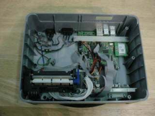
Click to zoom
Application Details
- Equipment Class
- DXX - Part 15 Low Power Communication Device Transmitter
- Date of Grant
- Oct 05, 2006
- Application Purpose
- Original Equipment
- Date of Application
- Jul 17, 2006
- Equipment Note
- RFID Reader
- Frequency Range
- 13.56000000 - 13.56000000
- Company
- Visionary Products, Inc.
- Country
- United States
Documents & Files
Document Text
Text extracted from the exhibit documents filed with the FCC. Open a document above to read the original.
Users Manual
SkyeTek RFID ENGINEERING SkyeTek RFID Readers SkyeRead M1 www.skyetek.com 5589 Arapahoe, 206B, Boulder, CO 80303 Phone: 720-565-0441 Fax: 720-565-8989 SkyeTek, LLC. SkyeRead M1 is a low-cost high-performance RFID reader module for easy integration into custom products and equipment. This multi-protocol device can read and write most industry standard 13.56MHz tags and smart labels. Use the M1 to quickly and easily add RFID technology to your new systems and equipment. Features: · Compliant with ISO15693 and ISO14443 · Contactless identification · No line of sight required · Reads and writes tags with up to 10k bits · Reads multiple tags simultaneously · Small module for easy integration · Optional external antenna · Simple ASCII protocol interface · Industry standard 13.56MHz operation label printers handheld data terminals vending machines barcode scanners any custom equipment Technical: Supply Current: RF Frequency: RF Modulation: RF Data Rate: Host Interface: 45mA @ 5V, 150mA @ 1.8V, 50uA standby 13.56MHz Tag-It HF (Texas Instruments) I·Code1 (Philips) PicoTag 2K * (Inside Contactless) GemWave * (TagSys) ISO-14443 * -A -B 10%/100% ASK (Reader to Tag) FSK/Machester (Tag to Reader) 26.6 kbits/s (ISO15693) 105.9 kbits/s (ISO14443) Serial RS232 or TTL (Rx/Tx/GND) 9600, 19200, 38400 kbits/s (N,8,1) SPI bus (SDI/SDO/SCK) 3MHz data rate I 2 C bus (SDA/SCL) 400kHz data rate Power Supply:1.2V to 5V operation 13.56MHz RFID Reader/Writer ISO-15693: Tag-It ICode My-d STM SkyeTek annouces SkyeRead M1 Dimensions:38mm x 40mm x 4mm For easy integration into: Antenna: ISO-15693 -2 -3: Tag-It HF-I (Texas Instruments) I·Code SLI (Philips) My-d SRF55V02/10P (Infineon) STM LRI512 (ST Microelectronics) Multi-Protocol RFID Read/Write Module * Available 2003 Read Range:75/150mm int/ext antenna (credit card) Compliance: FCC, CE, Industry Canada Internal or external 50-ohm antenna FLASH MCU: Firmware upgrades for new protocols Tag Compatibility: 38mm 40mm
Users Manual
SkyeTek M1 Troubleshooting Guide Problem: I can’t communicate with the reader using SkyWare (SkyWare responds with “No SkyeRead Device Detected”) via RS-232 or USB. Solution: 1. The reader is improperly connected either (See connection tutorial at the end of this document). 2. A com port is in use by some other application or improperly closed. Do an alt-ctrl-del and see if a previous version of SkyWare is still running. If not, restart the computer to make sure all com ports are closed and ready to use. 3. If a firmware upgrade was recently performed from any version prior to 001C to 001C or above, the reader ID of the reader may have been set to something other than 0xFF. In firmware version 001C or above, the reader will function exactly as before if the reader ID value is 0xFF. If the reader value is anything other than 0xFF, the reader will only respond to commands having the specific reader ID value programmed into its memory. In order to change the reader ID to 0xFF: 1. Connect the reader and open a terminal program. 2. Select the correct terminal settings, default baud rate is 9600. Settings are no parity bit, 8 data bits, 1 stop bit. 3. Send the following command with the reader connected. <CR>A041FF0201FF2C6E<CR> 4. The reader should respond with the following string: <LF>41538D<CR><LF> 5. Power cycle the reader. After a power cycle, SkyWare should detect the SkyeTek reader. Problem: I am unable to communicate with the reader via a terminal program or via code I am writing but the reader is detected by SkyWare. Solution: 1. The com port is in use by some other application or was not closed completely because of an irregular exit condition in SkyWare. Do an alt-ctrl-del and see if a previous version of SkyWare is still running. If not, restart the computer to make sure all com ports are closed and ready to use. 2. Com port was not initialized correctly. Make sure your terminal settings are correct. The correct settings should be 8 data bits, 1 stop bit, no parity bit. Default baud rate is 9600, but can be 19200, 38400, or 57600. Problem: I’m unable to read from or write to a tag with SkyWare. Solution: 1. Make sure the tag is in the field of the reader using the Get Tag ID command. If the internal antenna is used, make sure the tag is within 2 or 3 inches with a credit card sized tag or 1.5 to 2 inches for a wrist band sized tag. If the external antenna is being used make sure the tag is within 6-8 inches with a credit card sized tag. Tag should be within 3-5 inches of the external antenna for a wrist band sized tag. For smaller tags, the tag should be closer to the antenna. If SkyWare is unable to get a tag ID the tag is not in the field of the reader or not supported. 2. Make sure the tag is parallel to the antenna and in the field of the reader. This can be checked with a get tag ID command. 3. Make sure the tag is supported by our reader. Supported tag types and their standards can be found at the bottom of SkyWare. Make sure reads and writes are supported by our reader. Current supported tags for reads and writes are ISO15693, Tag-it HF, and I-Code1 tags. 4. The specific blocks you are trying to write to are locked. There is no way to tell if blocks on the tag are locked unless you try to write to a block and it fails while writing to another block passes. It is also not possible to unlock blocks once they are locked. Problem: I’m unable to read from or write to a tag when sending a command manually in SkyeTek protocol command builder or through a terminal program. Solution: 1. Check the command format and make sure that if writing in binary mode the message length field is included. 2. The starting block specified is incorrect for the specific tag you are trying to write. Please check SkyeTek protocol v2.0 available on the “downloads” page of the SkyeTek website for more information. 3. You are trying to write to an incorrect number of blocks. Please check the SkyeTek protocol v2.0 available on the “downloads” page of the SkyeTek website for more information. 4. The specific blocks you are trying to write to are locked. There is no way to tell if blocks on the tag are locked unless you try to write to a block and it fails while writing to another block passes. It is also not possible to unlock blocks once they are locked. 5. A valid tag type was not specified in the command. When reading or writing from an RFID tag the specific tag type must be included. A read or a write will not function correctly with an AUTO_DETECT tag type. Please check SkyeTek protocol v2.0 available on the “downloads” page of the SkyeTek website for more information. 6. A tag was not in selected state and a tag ID was not provided in the read or write command. Please check SkyeTek protocol v2.0 available on the “downloads” page of the SkyeTek website for more information. *All commands written in host software can be tested against the protocol command builder in SkyWare to verify correct commands and CRC values. Problem: The user port is not functioning correctly or I am unable to control the values on the port pins. Solution: 1. If you are unable to set the values of the GP/IO pins, configure first make sure the user port direction is configured as an output. For more information about this please check SkyeTek protocol v2.0 and also the M1 Reference Guide available on the “downloads” page of the SkyeTek website. 2. The port is enabled for LCD operation. When system parameter location contains the value 0xFF in memory, the user port will be configured for LCD operation. In order to change the user port operation back so that the user port functions as GP I/O, send the following command in ASCII mode: <CR> 20410A0100 003F <CR> The reader will respond with: <LF> 41 538D <CR><LF> After a power cycle, a write to system parameter 0x08 should change the port value correctly. For more information or details please see the M1 Reference Guide available on the “downloads” page of the SkyeTek website. Connec…
Text truncated - open the document above for the full version.
Block Diagram
Block Diagram: • 2.1033(b) (5) Please provide a block diagram showing the frequency of all oscillators in the device. The signal path and frequency shall be indicated at each block. The tuning range(s) and intermediate frequency(ies) shall be indicated at each block. A schematic diagram is also required for intentional radiators. SkyeRead M1 Schematic Diagram Microcontroller Fc = 13.56MHz Fc / 4 = 3.39MHz Microchip p/n PIC18F876A Reference Oscillator 13.56MHz S6700 HF RFID Rx/Tx Reader ASIC Texas Instruments p/n RI-R6C-001A RS-232 Transceiver Maxim p/n MAX3221 Boost Regulator (optional) 1.2V to 5V input 5V or 3.3V output Maxim p/n MAX1675 RFID Antenna Single- Loop PCB Trace
Cover Letter(s)
DNB Engineering Inc. Phone 1-800-887-4433/435-336-4433 1100 East Chalk Creek RD Fax: 435-336-4436 Coalville UT 84017 www.dnbenginc.com July 19, 2006 RE: FCC ID: SJN-CL2-RFID-M1, Form 731 Confirmation Number: EA955517 Request for LMA Modular Approval To Whom It May Concern: In order to obtain a modular transmitter approval, a cover letter requesting modular approval must be submitted and the numbered requirements identified below must be addressed in the application for equipment authorization. 1. The modular transmitter must have its own RF shielding. This is intended to ensure that the module does not have to rely upon the shielding provided by the device into which it is installed in order for all modular transmitter emissions to comply with Part 15 limits. It is also intended to prevent coupling between the RF circuitry of the module and any wires or circuits in the device into which the module is installed. Such coupling may result in non-compliant operation. The RFID module does not have its own shielding. 2. The modular transmitter must have buffered modulation/data inputs (if such inputs are provided) to ensure that the module will comply with Part 15 requirements under conditions of excessive data rates or over-modulation. The RFID module does have modulation/data inputs and the CL2 unit does interface to them. See Skyetek Reference Guide and CL2 schematics for details. 3. The modular transmitter must have its own power supply regulation. This is intended to ensure that the module will comply with Part 15 requirements regardless of the design of the power supplying circuitry in the device into which the module is installed. The module has its own boost regulator. 4. The modular transmitter must comply with the antenna requirements of Section 15.203 and 15.204(c). The antenna must either be permanently attached or employ a “unique” antenna coupler (at all connections between the module and the antenna, including the cable). Any antenna used with the module must be approved with the module, either at the time of initial authorization or through a Class II permissive change. The “professional installation” provision of Section 15.203 may not be applied to modules. The module has an on board internal antenna and will be configured to use it. The antenna is permanently attached. 5. The modular transmitter must be tested in a stand-alone configuration, i.e., the module must not be inside another device during testing. This is intended to demonstrate that the module is capable of complying with Part 15 emission limits regardless of the device into which it is eventually installed. Unless the transmitter module will be battery powered, it must comply with the AC line conducted requirements found in Section 15.207. AC or DC power lines and data input/output lines connected to the module must not contain ferrites, unless they will be marketed DNB Engineering Inc. Phone 1-800-887-4433/435-336-4433 1100 East Chalk Creek RD Fax: 435-336-4436 Coalville UT 84017 www.dnbenginc.com with the module (see Section 15.27(a)). The length of these lines shall be length typical of actual use or, if that length is unknown, at least 10 centimeters to insure that there is no coupling between the case of the module and supporting equipment. Any accessories, peripherals, or support equipment connected to the module during testing shall be unmodified or commercially available (see Section 15.31(i)). The module was tested in a stand alone configuration. No power lines or signal lines utilize ferrite beads. The length of the cable provided was longer than 10cm and is unmodified commercially available. 6. The modular transmitter must be labeled with its own FCC ID number, and, if the FCC ID is not visible when the module is installed inside another device, then the outside of the device into which the module is installed must also display a label referring to the enclosed module. This exterior label can use wording such as the following: “Contains Transmitter Module FCC ID: XYZMODEL1” or “Contains FCC ID: XYZMODEL1.” Any similar wording that expresses the same meaning may be used. The Grantee may either provide such a label, an example of which must be included in the application for equipment authorization, or, must provide adequate instructions along with the module which explain this requirement. In the latter case, a copy of these instructions must be included in the application for equipment authorization. A label for the RFID module will be provided, as well as the FCC ID for it will appear on the outside label for CL2. See attached labels. 7. The modular transmitter must comply with any specific rule or operating requirements applicable to the transmitter and the manufacturer must provide adequate instructions along with the module to explain any such requirements. A copy of these instructions must be included in the application for equipment authorization. For example, there are very strict operational and timing requirements that must be met before a transmitter is authorized for operation under Section 15.231. For instance, data transmission is prohibited, except for operation under Section 15.231(e), in which case there are separate field strength level and timing requirements. Compliance with these requirements must be assured. The module must be used only with the internal antenna. See Skyetek M1 Reference Guide for details. The module must be used only with the boost converter enabled. See Skyetek M1 Reference Guide for details. 8. The modular transmitter must comply with any applicable RF exposure requirements. For example, FCC Rules in Sections 2.1091, 2.1093 and specific Sections of Part 15, including 15.319(i), 15.407(f), 15.253(f) and 15.255(g), require that Unlicensed PCS, UNII and millimeter wave devices perform routine environmental evaluation for RF Exposure to demonstrate compliance. In addition, spread spectrum transmitters operating under Section 15.247 are required to address RF Exposur…
Text truncated - open the document above for the full version.
Cover Letter(s)
DNB Engineering Inc. Phone 1-800-887-4433/435-336-4433 1100 East Chalk Creek RD Fax: 435-336-4436 Coalville UT 84017 www.dnbenginc.com August 1, 2006 FCC ID: SJN-CL2-RFID-M1, Form 731 Confirmation Number: EA955517 RE: Correspondence Reference Number: 1285 To Whom It May Concern: Confidentiality is not requested for this device, I apologies for the inconvenience, but it was a oversight on my part that I did not notice during the filling process. Once again, I apologies for any inconveniences this may have caused, and thank you for your assistance and understanding in this matter. Sincerely Clay Allred Facility Manger (Utah Facility) DNB Engineering, Inc.
External Photos
Page 40 of 49 2.1033 (b) (7)Equipment Photographs Photo 1 External CL2 - Top Photo 2External CL2 - Bottom Photo 3Internal CL2 - Internal Combined Photo 4InternalCL2 - Internal Bottom Photo 5InternalCL2 - Internal Top (shows placement of RFID card) Photo 6InternalCL2 - RFID Module Front Photo 7InternalCL2 - RFID Module Back Page 41 of 49 Photo 1 External CL2 - Top Page 42 of 49 Photo 2External CL2 - Bottom Page 43 of 49 Photo 3Internal CL2 - Internal Combined
ID Label/Location Info
Ref er artwork questions to: Gar y Olsen VPI Engineering 801-495-2310 [email protected] om width: 1.725" height: 1.6" radius= 0.08" Pantone Cool Gray 5 M Pantone Black CompuSystems Model: Compulead II CSA ID: 231871 Input Rated: 100-240 Vac, 50-60 Hz, 1.8 A This unit includes FCC ID SJNVMX-100 for the radio and FCC ID SJN-CL2-RFID-M1. This device complies with part 15 of the FCC Rules. Operation is subject to the following two conditions: (1) This device may not cause harmful interference, and (2) this device must accept any interference received, including interference that may cause undesired operation. Do not print - outline is to show shape only. CompuLead II and CompuSystems are registered trademarks of CompuSystems, Inc., Broadview IL, 60155 U.S.A. Assembled in the U.S.A. CompuLead II Regulatory Label Artwork V00638100AG SHEET 1 OF 1 SCALE: 1:1 REV DWG. NO. TITLE: DateDrawn Cog E P eer P rog Mgr QA 11814 South Elect ion Rd Ste 200 Draper, UT 84020 PH# (801) 495-2310 FAX# (801) 495-2255 engineeringengineering
ID Label/Location Info
Serial: V006136_01.1005 Model #: RFID Skyetek M1 FCCID: SJN-CL2-RFID-M1 This device complies with Part 15 of the FCC Rules.
Internal Photos
Page 40 of 49 2.1033 (b) (7)Equipment Photographs Photo 1 External CL2 - Top Photo 2External CL2 - Bottom Photo 3Internal CL2 - Internal Combined Photo 4InternalCL2 - Internal Bottom Photo 5InternalCL2 - Internal Top (shows placement of RFID card) Photo 6InternalCL2 - RFID Module Front Photo 7InternalCL2 - RFID Module Back Page 43 of 49 Photo 3Internal CL2 - Internal Combined Page 44 of 49 Photo 4InternalCL2 - Internal Bottom Page 45 of 49 Photo 5InternalCL2 - Internal Top (shows placement of RFID card) Page 46 of 49 Photo 6InternalCL2 - RFID Module Front Page 47 of 49 Photo 7InternalCL2 - RFID Module Back
Operational Description
Installation and Tune-up Instructions: • 2.1033(b) (3) A copy of the installation and operating instructions to be furnished the user. A draft copy of the instructions may be submitted if the actual document is not available. The actual document shall be furnished to the FCC when it becomes available. Installation and Tune-up Instructions for the SkyeRead M1 and the SkyeRead EA1 are found in their respective Product Reference Guides. The most current versions of the SkyeRead Reference Guides are included in this document submittal package. For the most current version of published SkyeTek Product Reference Guides please visit www.skyetek.com.
Operational Description
• Provide a statement for how your device Complies with FCC15.203 Antenna requirement: An intentional radiator shall be designed to ensure that no antenna other than that furnished by the responsible party shall be used with the device. The use of a permanently attached antenna or of an antenna that uses a unique coupling to the intentional radiator shall be considered sufficient to comply with the provisions of this section. The manufacturer may design the unit so that a broken antenna can be replaced by the user, but the use of a standard antenna jack or electrical connector is prohibited. This requirement does not apply to carrier current devices or to devices operated under the provisions of §§15.211, 15.213, 15.217, 15.219, or 15.221. Further, this requirement does not apply to intentional radiators that must be professionally installed, such as perimeter protection systems and some field disturbance sensors, or to other intentional radiators which, in accordance with §15.31(d), must be measured at the installation site. However, the installer shall be responsible for ensuring that the proper antenna is employed so that the limits in this part are not exceeded. • The SkyeRead M1 from SkyeTek, Inc. is a low power (200mW RF power output maximum) RFID reader/writer intended for installation by technical professionals. The M1 comes with an integrated, on-board antenna. The M1 also has an antenna jack that allows the installer to disable the internal antenna and instead connect an external antenna to the M1. The SkyeRead EA1 is a suitable and certified external antenna module for use with the SkyeRead M1.
Schematics
NC NCNC NC NC NC NC 68 R27 NC C710uF C100.1uF 68 R23 68 R24 DNS R25 DNS R26 68 R19 68 R20 68 R21 68 R22 68 R14 68 R17 68 R18 C310uF C50.1uF C80.1uF C18 0.1uF C20.1uF C2010nF0.1uFC16 0.1uFC17 C410nF C1410nF 34 J1:AH 31 J1:AE 32 J1:AF 29 J1:AC 28 J1:AB 25 J1:Y 26 J1:Z 23 J1:W 22 J1:V 19 J1:S 20 J1:T 16 J1:P 17 J1:Q 14 J1:N 13 J1:M 10 J1:J 11 J1:K 8 J1:H 7 J1:G 5 J1:E 4 J1:D 2 J1:B 1 J1:A C910nF C610nF C130.1uF C190.1uF 0.1uFC15 R2910K R2810K 0.1uF C12 0.1uF C11 24 J1:X 27 J1:AA 30 J1:AD 33 J1:AG 18 J1:R 15 J1:O 12 J1:L 21 J1:U 9 J1:I 6 J1:F 3 J1:C 43 NC 30 XCLK2 46 SIO_C 27 D3 1 SVDD 24 D0 4 DEVDD 21 ADGND 37 DOVDD 34 D7 31 PCLK 9 SRAMT 12 EXPSTB 15 VcCHG 18 ASUB 32 D5 33 D6 36 D9 35 D8 38 DOGND 39 HREF 41 VSYNC 44 NC 45 SIO_D 47 VcCHG 48 SGND 2 VrHIGH 3 NBIT 5 DEGND 20 ADVDD 22 DVDD 23 DGND 25 D1 26 D2 28 D4 29 XCLK1 14 FSIN 16 AVDD 17 AGND 8 FREX 10 RESET 11 SCCB_E 13 VGA 42 NC 7 PWDN 40 CHSYNC 6 VrLOW 19 VrAD2 U1 U-OMNIVISION-OV9120-LCC48 R9 28 D8 R13 28 D12 R8 28 R10 28 D9 R16 28 D14 R6 28 R12 28 D11 R15 28 D13 R5 28 R7 28 D6 R11 28 D10 R4 28 D3 C147uF R110K IRLML6401Q1 R2 28 D7 D1 D5 R3 28 D2 D4
Schematics
15 J1:O 14 J1:N 12 J1:L 11 J1:K 8 J1:H 9 J1:I 6 J1:F 5 J1:E 2 J1:B 3 J1:C SW13 SW5SW9SW1 C61.0uF R21K SW14 SW6 SW10 SW2 C51.0uF R41K SW15 SW7 SW11 SW3 C71.0uF R11K SW16 SW8 SW12 SW4 C41.0uF 16 J1:P 7 J1:G 4 J1:D 13 J1:M 10 J1:J 1 J1:A C91.0uF C1122uF 0.1uFC3 26 J2:Z 25 J2:Y 23 J2:W 22 J2:V 19 J2:S 20 J2:T 17 J2:Q 16 J2:P 13 J2:M 14 J2:N 10 J2:J 11 J2:K 8 J2:H 7 J2:G 5 J2:E 4 J2:D 1 J2:A 2 J2:B 24 J2:X 21 J2:U 18 J2:R 15 J2:O 12 J2:L 9 J2:I 6 J2:F 3 J2:C R31K C1022uF
Schematics
N/C D20 DNS(B130LAW) C290.1uF 10uFC126 R295DNS(100K) R213100K 10uFC34 B13003-3.0V SW1 R297 DNS(576K) C2122uFC3122uF R337100K R331100K DNS(0.1uF) C200 10uFC64 10uFC58 R32830.1K N/C R285 DNS(51.1K) R286 DNS(51.1K) C201 330pF C213 330pF Power for: Display 200KR325604KR326 340KR294 Power for: SD Card Ethernet RS232 IR Display R122100K C203DNS(1.0uF) R319100K DNS(340K)R287R292DNS(953K) C2244.7pF 200KR291200KR308340KR312 Power for: Au1100 Processor Xilinx FPGA Flash Memory Bluetooth R303100K 10uH L2 DNS(B130LAW) D23 R102 0 X432.768kHz C202DNS(0.1uF) R296DNS(51.1K)C1200.1uF C132DNS(1.0uF) DNS(10uF)C193 DNS(10uH) L3 R332100K Power for: Display Q8IRLML6401 DNS(1uF)C209 R330100K Power for: Au1100 Processor Xilinx FPGA SDRAM R304100K Power for: Au1100 Processor Xilinx FPGA C56DNS(1.0uF) Power for: Display Backlight R305100K R33682.5K3A 20V D2 R293 121K C22022uF R306 121K Power for: Display C28 DNS(0.1uF) 10uH L1 TPS62006 U24 DNS(10uH) L4 Q9IRLML2502 R10110K D21DNS(B130LAW) U25 DNS(LT1945) 10uFC44 60.4KR28960.4KR307 R323100K C42DNS(1uF)C50DNS(1uF) C5722uF C62470pF C194DNS(100pF)C199DNS(4.7pF) 10uH L6 C20422uF 10uH L7 10uH L5 Power for: USB Hub Daughter Cards Analog Board U17 TPS62207 U27 DNS(MAX1616) Q5IRLML2502 Q6IRLML6401 2 VDD 3 GND 1 RST DNS(MCP120T-300)U15 U26 LTC3440 U21 LTC3402 U28 LTC3440 NCNCNCNC J31 NCNC NCNC 7 J20:G 6 J20:F 3 J20:C 4 J20:D 1 J20:A C2768uFC3268uF10uFC13710uFC177 C968uF C4922uF 10uFC179 10uFC18010uFC89 10uFC122 10uFC16 10uFC22 R284100K C3022uF C6522uF10nFC167 10nFC17110nFC162 10nFC163 10nFC174 10nFC175 1.0KR279 C722uF C1868uF10nFC166 10nFC16810nFC16510nFC176 1.0KR282 1.0KR283 10nFC157 8 J20:H 5 J20:E 2 J20:B 10R258 10nFC151 X232.768kHz 33KR263 10 J21:J 4 J21:D 6 J21:F 12 J21:L 9 J21:I 11 J21:K 5 J21:E 14 J21:N R281 22 C3722uF C4368uF10uFC178 10uFC181 10uFC149 10nFC161 10uFC24 10nFC170 8 J21:H 7 J21:G 2 J21:B 1 J21:A 13 J21:M C6322uF C9622uF10nFC172 10nFC17310nFC16410nFC169 1.0KR290 1.0KR280 C2622uF 12.0MHzX3 3 J21:C C2322uF10R262 33KR266 33KR93 U13:A Au1100 NC NCNC NC NC 68 R267 5 J18:E 4 J18:D 2 J18:B 1 J18:A 0 R49 D13DNS(SM12T1) D14DNS(SM12T1) C1950.1uF D17DNS(SM12T1) C38DNS(0.1uF) NC NCNC R271100K 5.1K R268 68 R269 6 J18:F 3 J18:C R46 22 R48 22 R111 22 R112 22 10KR274 10KR2765.1KR275 DNS(0) R60 D18SM12T1 C53DNS(0.1uF) R119100K R278100K Q28 IRLML6401 10K R270 10K R50 R277 DNS(0) 5 J17:E 2 J17:B 3 J17:C D11DNS(SM12T1) D12DNS(SM12T1) D15DNS(SM12T1) D19DNS(SM12T1) C1980.1uF R288 DNS(0) C1970.1uF D22DNS(SM12T1) C36DNS(0.1uF) C39DNS(0.1uF) R272100K C1960.1uF C152DNS(0.1uF) 10KR273 Q3IRLML64011.5KR47 4 J17:D 6 J17:F 1 J17:A C480.1uF D10DNS(SP0505B) D16SM12T1 C40DNS(0.1uF) U22 DNS(MAX3471) EXC3BP121H R202 EXC3BP600H R193 EXC3BP600H R200 U13:D Au1100 U19 MAX3221 NC NC NCNCNC NCNC 68 R88 68 R85 68 R68 68 R246 68 R67 68 R248 68 R66 68 R249 68 R81 68 R80 68 R228 68 R62 NCNC NCNCNCNC 68 R69 68 R84 68 R86 68 R221 68 R223 68 R224 68 R245 68 R65 68 R82 68 R83 68 R225 68 R226 68 R227 68 R252 68 R63 68 R64 68 R78 68 R79 68 R251 NCNC C20DNS(0.1uF) R56DNS(15K) R53DNS(15K) R52DNS(15K) C910.1uF 10uFC105 C940.1uF C1270.1uF C1180.1uF C1190.1uF C970.1uF 68 R247 68 R250 DNS(549K)R57 68 R71 68 R222 68 R89 68 R238 68 R239 68 R92 68 R74 68 R241 C19DNS(1uF)R54DNS(15K) DNS(10K)R55 R58DNS(15K) 68 R72 68 R219 68 R243 68 R244 68 R70 68 R76 68 R90 68 R218 68 R220 68 R237 68 R242 68 R75 68 R91 68 R215 68 R217 68 R240 C980.1uF C990.1uF C1250.1uF D7 DNS(SP0505B) 68 R73 68 R87 68 R216 D1 DNS(SP0505B) U13:G Au1100 K4M28323LF-SN1L U9 U13:C Au1100 NCNCNCNCNCNCNCNCNCNCNC NCNCNCNCNCNCNCNCNCNCNC NCNCNCNCNCNCNC NCNC R100100K R99100K 10nFC140 10nFC156 R254100K R259100K R261100K R114 0 R98100K R113 0 R115 0 R116 0 R117 0 R118 0 10uFC139 10nFC153 R212100K U12 S29GL256M U13:B Au1100 22 J3:V 21 J3:U 18 J3:R 19 J3:S 15 J3:O 16 J3:P 12 J3:L 13 J3:M 9 J3:I 10 J3:J 7 J3:G 6 J3:F 4 J3:D 3 J3:C 17 J3:Q 20 J3:T 8 J3:H 5 J3:E 14 J3:N 11 J3:K 2 J3:B R59100K 1 J3:A R182 0 R195 0 R197 0 DNS(10K)R302 R186 0 R188 0 DNS(10K)R318 DNS(10K)R153 10uF C10 E Q20 DNS(DTC114YET) E Q22 DNS(DTC114YET) C81.0uF 10uF C83 DNS(10K)R300 C791.0uF DNS(10K)R316 C17 1.0uF DNS(10K)R313 C85 1.0uF 10uF C86 C67 1.0uF 10uF C68 DNS(10K)R298 C691.0uF R35 DNS(0) R34 DNS(0) R37 DNS(0) R36 DNS(0) R167 0 R187 0 DNS(10K)R301 DNS(10K)R317 R189 0 R22 DNS(0) R23 DNS(0) R25 DNS(0) R27 DNS(0) R28 DNS(0) R33 DNS(0) 68 R178 68 R179 R194 0 R196 0 R20 DNS(0) R21 DNS(0) R29 DNS(0) R30 DNS(0) R31 DNS(0) R184 DNS(0) R172 DNS(0) R162 0 R177 0 R166 0 R175 0 E Q16 DNS(DTC114YET) E Q18 DNS(DTC114YET) DNS(10K)R299 DNS(10K)R315 C11 1.0uF 10uFC75 C84 1.0uF E Q15 DNS(DTC114YET) E Q17 DNS(DTC114YET) E Q19 DNS(DTC114YET) E Q21 DNS(DTC114YET) 10uFC74 10uF C92 E Q11 DNS(DTC114YET) E Q12 DNS(DTC114YET) E Q13 DNS(DTC114YET) DNS(10K)R314 10uFC66 Note: The ADC MCP3001, U23, can be run at 3.3V or 5.0V. - If run at 5.0V, U2 must be placed. - If run at 3.3V, R166, R167 and R175 must be placed. E Q14 DNS(DTC114YET) R201 DNS(0) 270 R192 NC C1030.1uF C1130.1uFC880.1uF C1060.1uF C1070.1uF C1240.1uF C870.1uF C1080.1uF C1000.1uF C1140.1uFC1040.1uF C1120.1uF R45 DNS(0) R190 0 10uFC138 10uFC158 10uFC81 10uFC131 R229100K R203100K 270 R210 R211100K DNS(33K)R19933KR198 C900.1uF C1170.1uF C930.1uF C950.1uF C1210.1uF C1230.1uF 10uFC148 68 R61 3 J5:C 4 J5:D 1 J5:A C1010.1uF C1100.1uF C1150.1uF C1160.1uFC1110.1uF C1280.1uF C1290.1uF C1300.1uF R209 0 Q10DNS(IRLML6401) R155DNS(100K) R191100K 2 J5:B 6 J5:F 5 J5:E C1020.1uF C1090.1uF 10uFC145 Q23IRLML6401 33KR156 Q4IRLML6401 Q27IRLML6401 10K R26 33KR41 100KR208 100KR207 DNS(100K)R206 10K R32 0R44 12 34 LED1 Dual LED 100KR95 7 J9:76 J9:6 4 J9:4 3 J9:3 1 J9:1 J11 Q1NPN B130LAWD6 C61uF R181 0 5 J9:52 J9:2 68R233 270R234 DNS(68)R232 DNS(EVQP2402W) SW3 8 J9:8 Q2PNP Q25IRLML6401 Q26IRLML6401 LED2 DNS(EVQP2402W) SW2 100KR96 Q24DNS(IRLML6401) NC NC NC NCNCNCNCNCNCNCNCNCNCNCNCNCNCNCNCNC NC NC NCNCNCNCNCNCNCNCNCNC C1540.1uF C1550.1uF 10KR253 C1410.1uF C1600.1uF C1330.1uF C1350.1uF 68 R97 10uFC144 10uFC146 R23110K R7749.9R23549.9 R25610K R255121 R257121 C1430.1uF 1.5KR260 C14…
Text truncated - open the document above for the full version.
Schematics
C19 330pF R22 121K D2 3A 20V C23 820pF R20121K C1422uF R17604K 3.01KR922KR2 C13100nF C4820pF R19 1 R11 1 R3310K R51 54.9K C22 820pF R50 54.9K R2910K C25.1uF C1210uF C31.1uF10nFC26 C270.1uF R2360.4K R2410K L1 10uH R18200K 100KR3 R811K 9.09KR6 1KR151KR10 R324.7K R5910K 47KR13 C5100nF 10nFC16 15.8KR14 Q1 MMBF0201NLT1 Q3 MMBF0201NLT1 D1 LM4040 2.5V R124.22K 1KR5 Q8IRF9Z34NS C6820pF C3010nF 10nFC9 C1522uF Q2 MMBF0201NLT1 Q4 MMBF0201NLT1 2KR7 2SC3617Q6 R16100K C10820pF U4 LTC3440 4 J3:D 3 J3:C 1 J3:A 1.0uFC18 C21 220uF C810nF 5 J3:E 2 J3:B C29470pF C280.1uF R40DNS 0 R43 47KR36 0 R38 E DNS Q9 R26DNS R21DNSR27DNSR41DNSR45DNS R1DNSR39DNSR46DNSR49DNS R52220 R54DNS 0 R37 0 R61 C1722uF C3100uF C70.1uF R5780.6K R58200 R56470 E DNS Q13 E DNS Q15 0 R30 0 R34 4 J4:D 2 J4:B 1 J4:A 15 J2:O 14 J2:N 12 J2:L 11 J2:K 9 J2:I 8 J2:H 6 J2:F 5 J2:E 3 J2:C 2 J2:B 5 J1:E 4 J1:D 2 J1:B 20 J5:T 18 J5:R 17 J5:Q 14 J5:N 15 J5:O 12 J5:L 11 J5:K 9 J5:I 8 J5:H 6 J5:F 5 J5:E 3 J5:C 2 J5:B 3 J4:C 16 J2:P 10 J2:J 13 J2:M C200.1uF 4 J2:D 7 J2:G C1.1uF 1 J2:A C11.1uF 6 J1:F 3 J1:C 1 J1:A C24100nF 19 J5:S 13 J5:M 10 J5:J 16 J5:P 7 J5:G 1 J5:A 4 J5:D 0 R4 0 R25 0 R31 0 R42 0 R44 0 R53 E DNS Q17 E DNS Q18 R35DNSR60DNS47KR28 D3SP0505BAJT 1.0uFC2 4.7KR55 E DNS Q5 E DNS Q7 E DNS Q10 E DNS Q14 E DNS Q16 E DNS Q19 0 R47 0 R48 E DNS Q11 Q20IRLML2502 E DNS Q12 E DNS Q21
Schematics
C2 1.0uF C11.0uF R10 2.2K 2.2KR11 Q3 MMBT4401 R9 100 R7 160 R1 DNS 0.1uFC3 R14 2.2K R15 2.2K R8 160 R30 0 R4 0 R2 2.2KR12 C522uF 0 R5 0 R6 0 R16 C41.0uF 2.2KR13 SML-LX3632SISUGSBCD1 Q1 MMBT4401 Q2 MMBT4401 MLT-03GCSPK1
Test Report
Application for Certification For a RF Transmitter Visionary Products, Inc. 11814 South Election Road, Suite 200 Draper, UT 84020 Computer Interface Device w/ RFID M/N: CL2 FCC ID: SJN-CL2-RFID-M1 REPORT # RV68044B-003 This report was prepared in accordance with the requirements of the FCC Rules and Regulations Part 2, Subpart J, 2.1033, Part 15.225, and other applicable sections of the rules as indicated herein. Prepared By: DNB Engineering, Inc. 5969 Robinson Avenue Riverside, CA 92503 28 Dec 2005 Page 2 of 48 TABLE OF CONTENTS Paragraph numbers in this report follow the application section numbers found in the FEDERAL COMMUNICATIONS COMMISSION Rules and Regulations, Part 2, Subpart J for Certification of electronic equipment. TABLE OF CONTENTS...............................................................................................................2 1.0ADMINISTRATIVE DATA..............................................................................................3 1.1Certifications and Qualifications.........…
Text truncated - open the document above for the full version.
Contact Information
Applicant
Jeremy Williams(Engineer)
Technical Contact
DNB Engineering, Inc.Les Payne
[email protected]951-637-2630
5969 Robinson Ave. · Riverside, California · United States
Non-Technical Contact
DNB Engineering, Inc.Clay Allred
[email protected]435-336-4433
Test Firm
DNB Engineering, Inc.Michael Neis
Technical Specifications
| # | Rule Parts | Frequency Range | Power Output |
|---|---|---|---|
| 1 | 15C | 13.56 MHz - 13.56 MHz | - |
Other Applications from Visionary Products, Inc.
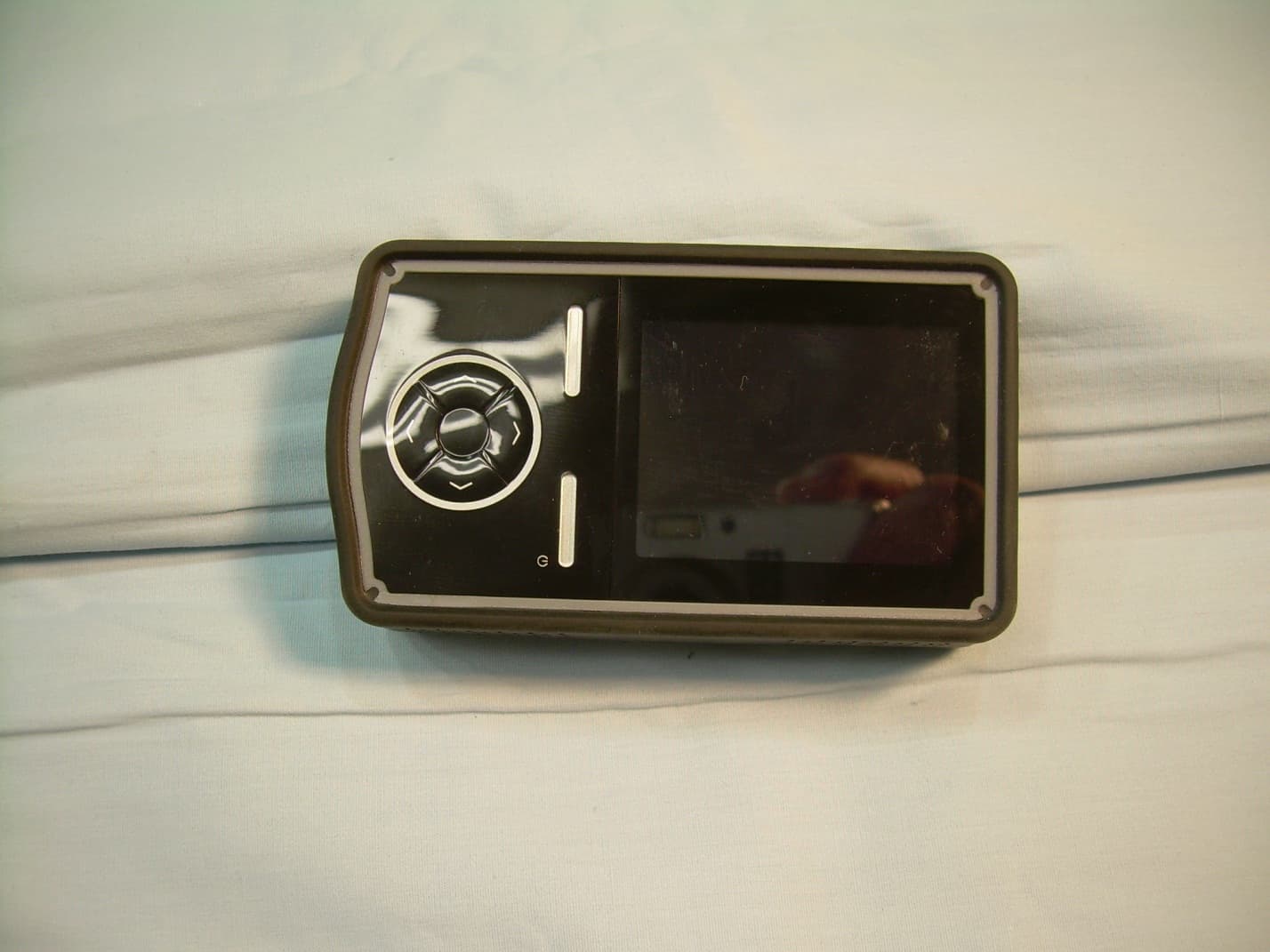
SJNMRDX
Apr 21, 2014Handheld Radiation Detection Device
Equipment Class
DTS - Digital Transmission System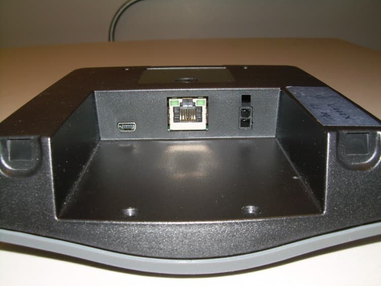
SJNRDX
Dec 05, 2012RADIATION DETECTION DEVICE
Equipment Class
DTS - Digital Transmission System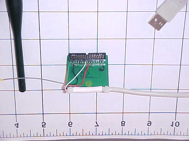
SJNVMX-100
Feb 08, 20052.4GHz Transmitter
Equipment Class
DSS - Part 15 Spread Spectrum Transmitter