SJNRDXRADIATION DETECTION DEVICE
Visionary Products, Inc.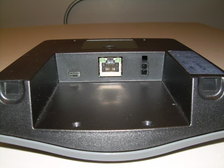
Click to zoom
Application Details
- Equipment Class
- DTS - Digital Transmission System
- Date of Grant
- Dec 05, 2012
- Application Purpose
- Original Equipment
- Date of Application
- Dec 05, 2012
- Equipment Note
- RADIATION DETECTION DEVICE
- Frequency Range
- 2405.00000000 - 2475.00000000
- Company
- Visionary Products, Inc.
- Country
- United States
Documents & Files
Document Text
Text extracted from the exhibit documents filed with the FCC. Open a document above to read the original.
Users Manual
INSTALLATION AND OPERATING INSTRUCTIONS FOR THE RADIATION DETECTION SYSTEM D-tect Systems Group Visionary Products Inc. 11814 South Election Road, Suite 200 Draper, UT 84020 www.dtectsystems.com 6/12/2012, Rad-DX Manual Version 2.0 Page 2 Table of Contents 1 Introduction.............................................................................................................................. 3 2 System Components ................................................................................................................ 3 3 Networking Options Overview ................................................................................................ 5 4 Monitoring and Controlling the DX using the LCD Screen .................................................... 7 4.1 Explanation of Networking Icons on the LCD Touch Screen ........................................ 8 5 Monitoring and Controlling the Rad-DX in a Network using the DX Dashboard .................. 9 5.1 Signing In ........................................................................................................................ 9 5.2 Home Screen ................................................................................................................. 10 5.2.1 Home Screen Buttons ............................................................................................... 13 5.2.2 Settings Button ......................................................................................................... 13 5.2.3 Help Button ............................................................................................................... 14 5.3 Radiation Level Graph Button ...................................................................................... 15 5.4 Device Configuration Button ........................................................................................ 16 5.4.1 Device Tab ................................................................................................................ 16 5.4.2 Properties Tab ........................................................................................................... 17 5.4.3 Alarm Tab ................................................................................................................. 18 5.4.4 Ethernet Tab ............................................................................................................. 19 5.4.5 WiFi Tab ................................................................................................................... 20 5.4.6 Mesh Tab .................................................................................................................. 21 5.4.7 Firmware Update Tab ............................................................................................... 22 6 Installation and Set-up of your Rad-DX ................................................................................ 23 6.1 Physical Installation ...................................................................................................... 23 6.1.1 Junction Box Method ................................................................................................ 23 6.1.2 Plug-In Wall Mount Method .................................................................................... 24 6.2 Installing a DX network using the D-tect Cloud Network ............................................ 25 6.2.1 User Name and Password ......................................................................................... 25 6.2.2 DX Utility Application Installation Instructions ...................................................... 25 7 Specifications ......................................................................................................................... 31 8 Technical Support .................................................................................................................. 32 Warranty for D-tect System Products ............................................................................................. 34 6/12/2012, Rad-DX Manual Version 2.0 Page 3 1 Introduction The Rad-DX is a security and inspection system that detects emissions from radioactive material. The Rad-DX system can operate as a stand-alone detector or as part of a larger rad-DX network monitoring a building or facility. 2 System Components There are several configurations available for a Rad-DX system. Four styles are available: black with LCD, black without LCD, white with LCD, and white without LCD. Figure 1: Rad-DX Versions - black and white, LCD and non-LCD 6/12/2012, Rad-DX Manual Version 2.0 Page 4 Other hardware components included with each Rad-DX include: Mounting Bracket USB Cable Wire Nuts and Mounting Screws “Pigtail” Wire Harness Power Cable (black or white depending on color of Rad-DX) Table 1: Additional Rad-DX Hardware 6/12/2012, Rad-DX Manual Version 2.0 Page 5 3 Networking Options Overview Your Rad-DX can operate in a variety of configurations. Each Rad-DX unit can function as a stand-alone unit or form part of a radiation detector network with other Rad-DX units. Configuration options are: Stand-Alone Operation: The Rad-DX can be controlled and monitored via the touch-screen LCD on the unit. D-tect Cloud Network: The D-tect Cloud Network is the easiest method to control and monitor a network of Rad-DX detectors. It also allows the detectors to be monitored via smartphone, tablet, or PC. Setting up your Rad-DX unit within the Cloud Network will require a PC with an internet connection. All information sent over the Cloud is SSL encrypted. DX Network Assistant Appliance: Our Rad-DX Assistant appliance allows a RAD-DX network to operate behind a firewall that blocks access to the internet. The DX Network Assistant is a computer pre-loaded with all the software needed to control and monitor a network of Rad-DX detectors. Installation of the network is quick and very easy. Locate the DX Network Assistant anywhere in your facil…
Text truncated - open the document above for the full version.
External Photos
Front View of the EUT Back View of the EUT View of the Bottom of the EUT Showing Interface Ports
ID Label/Location Info
Model: Rad-DX FCC ID: SJNRDX This device complies with part 15 of the FCC Rules. Operation is subject to the following two conditions: (1) This device may not cause harmful interference, and (2) this device must accept any interference received, including interference that may cause undesired operation. IC: 10637A-RADXLCD1PMT Made in U.S.A.D-tect Systems www.dtectsystems.com Rad-DX Serial Number Label V01906704 SHEET 1 OF 1 SCALE: 1:1 REV DWG. NO. TITLE: Refer artwork questions to: Gary Olsen VPI Engineering 801-495-2310 [email protected] DateDrawn Cog E Peer Prog Mgr QA 11814 South Election Rd Ste 200 Draper, UT 84020 PH# (801) 495-2310 FAX# (801) 495- 2255 engineeringengineering Serial numbers to begin with 880050 Serial numbers to increment by one for each label (for example, 1st label serial number is 880050, 2nd label serial number is 880051, etc.) Bar code to be DataMatrix format Serial number sample: DataMatrix Code Instructions: Data encoded in DataMatrix code is the Serial Number only. Shape is drawn to scale. Create die with dimensions of 1.75” wide x 1.625” high with .06 “ rounded corners. Model: Rad-DX FCC ID: SJNRDX This device complies with part 15 of the FCC Rules. Operation is subject to the following two conditions: (1) This device may not cause harmful interference, and (2) this device must accept any interference received, including interference that may cause undesired operation. IC: 10637A-RADXLCD1PMT Made in U.S.A.D-tect Systems www.dtectsystems.com Unique Data Matrix to be placed here (see sample), dotted outline not included in final label. S/N: 880050
Internal Photos
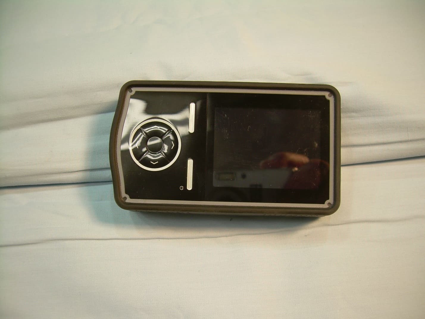
EUT with Front Cover Removed Front View of the Display Module Back View of the Display Module View of the EUT with Front Cover and Display Removed View of the Front Side of the Main PCB View of the Back Side of the Main PCB View of the Back Side of the Main PCB with Interface PCB Removed View of the Front Side of the Interface PCB View of the Back Side of the Interface PCB View of the Scintillation Tube and Component Side of the PCB View of the Scintillation Tube and Trace Side of the PCB View of the Plastic Housing Showing Antennas, Scintillation Tube, and PCB Placement
RF Exposure Info
The limits for Maximum Permissible Exposure (MPE) at different frequencies are set forth in C.F.R. 47 section 1.1307(b) and 1.13.10. The limit for General Population / Uncontrolled Exposures for our frequency of 2.4GHz is set to be 1 mW/cm ². The limit is compared to our device by measuring the Output Power for our frequency and calculating the Power Density according to the following formula: Power Density = (Power Out*Antenna Gain) / (4*π*r²) The product under test is the Rad-DX which is produced by VPI Engineering for D-tect Systems. The Rad-DX uses two of the same antennas for the 802.11bg and 802.15.4 transmitters. The gain of the antenna is 2.5dBi. These measurements and calculations for the Rad-DX 802.11bg transmitter are listed in the table below: Channel Frequency MHz 802.11b Measured Output Power (mW) Power Density at r=20cm (mW/cm²) 802.11g Measured Output Power (mW) Power Density at r=20cm (mW/cm²) 1 2412 34.91 0.017362769 53.58 0.026648443 2 2417 160.32 0.07973644 6 2437 28 0.013926025 154.53 0.076856737 10 2457 126.18 0.062756637 11 2462 27.04 0.013448561 44.16 0.021963331 These measurements and calculations for the Rad-DX 802.15.4 transmitter are listed in the table below: Channel Frequency MHz 802.15.4 Measured Output Power (mW) Power Density at r=20cm (mW/cm²) 11 2405 46.34 0.023047571 18 2440 44.06 0.021913595 25 2475 38.19 0.018994103
Test Report
Nemko-CCL, Inc. 1940 West Alexander Street Salt Lake City, UT 84119 801-972-6146 Test Report Certification Test Of: RAD-DX FCC ID: SJNRDX Test Specifications: FCC PART 15, Subpart C Test Report Serial No: 211989-4.1 Applicant: Visionary Products, Inc. 11814 S. Election Road, Suite 200 Draper, UT 84020 Dates of Test: June 19 – 21, 2012 July 3 & July 5, 2012 Report Issue Date: September 4, 2012 Accredited Testing Laboratory By: NVLAP Lab Code 100272-0 Nemko-CCL, Inc. TEST REPORT: 211989-4.1 REPORT ISSUE DATE: 09/04/2012 Page 2 of 113 CERTIFICATION OF ENGINEERING REPORT This report has been prepared by Nemko-CCL, Inc. to document compliance of the device described below with the requirements of Federal Communications Commission (FCC) Part 15, Subpart C. This report may be reproduced in full. Partial reproduction may only be made with the written consent of the laboratory. The results in this report apply only to the sample tested. - Applicant: Visionary Products, Inc. - Manufacturer: Visionary Products, Inc. - Brand Name: D-tect Systems - Model Numbers: RAD-DX - FCC ID Number: SJNRDX On this 4 th day of September 2012, I, individually and for Nemko-CCL, Inc., certify that the statements made in this engineering report are true, complete, and correct to the best of my knowledge, and are made in good faith. Although NVLAP has recognized that the Nemko-CCL, Inc. EMC testing facilities are in good standing, this report must not be used to claim product certification, approval, or endorsement by NVLAP, NIST, or any agency of the federal government. Nemko-CCL, Inc. Tested by: Norman P. Hansen EMC Technician Reviewed by: Thomas C. Jackson General Manager Nemko-CCL, Inc. TEST REPORT: 211989-4.1 REPORT ISSUE DATE: 09/04/2012 Page 3 of 113 TABLE OF CONTENTS PAGE SECTION 1.0 CLIENT INFORMATION .................................................................................4 SECTION 2.0 EQUIPMENT UNDER TEST (EUT) ..................................................................5 SECTION 3.0 TEST SPECIFICATION, METHODS & PROCEDURES .............................8 SECTION 4.0 OPERATION OF EUT DURING TESTING ..................................................14 SECTION 5.0 SUMMARY OF TEST RESULTS ...................................................................15 SECTION 6.0 802.11bg TRANSCEIVER – MEASUREMENTS AND RESULTS ..............16 SECTION 7.0 802.15.4 TRANSCEIVER – MEASUREMENTS AND RESULTS................67 APPENDIX 1 TEST PROCEDURES AND TEST EQUIPMENT ..........................................88 APPENDIX 2 PHOTOGRAPHS ................................................................................................94 APPENDIX 3 802.15.4 TRANSMITTER DUTY CYCLE CALCULATIONS ....................113 Nemko-CCL, Inc. TEST REPORT: 211989-4.1 REPORT ISSUE DATE: 09/04/2012 Page 4 of 113 SECTION 1.0 CLIENT INFORMATION 1.1 Applicant: Company Name: Visionary Products, Inc. 11814 S. Election Road, Suite 200 Draper, UT 84020 Contact Name: Jeremy Williams Title: Engineer 1.2 Manufacturer: Company Name: Visionary Products, Inc. 11814 S. Election Road, Suite 200 Draper, UT 84020 Contact Name: Jeremy Williams Title: Engineer Nemko-CCL, Inc. TEST REPORT: 211989-4.1 REPORT ISSUE DATE: 09/04/2012 Page 5 of 113 SECTION 2.0 EQUIPMENT UNDER TEST (EUT) 2.1 Identification of EUT: Brand Name: D-tect Systems Model Number: RAD-DX Serial Number: None 2.2 Description of EUT: The RAD-DX is a gamma radiation detector and monitor. The RAD-DX communicates with other devices using Ethernet, 802.15.4 Zigbee, or 802.11bg WiFi. The RAD-DX typically is powered by the AC mains and has an ICR 18500 type battery for backup. The RAD-DX 802.11bg transceiver uses 11 channels in the 2400 to 2483.5 MHz frequency range. All tests were performed at channels 1, 6, and 11 using 802.11b and 802.11g. Additional testing, because of the different channel power settings of the device, was also performed at channels 2 and 10. The RAD-DX 802.11bg transceiver uses a Taoglas FXP73 flexible antenna with a manufacturer stated maximum gain of 2.5 dBi. The channels and the maximum transmitter power settings to be incorporated in production software are shown below. Channel Frequency (MHz) Power Setting 802.11b 802.11g 1 2412 +16 +14 2 2417 +16 +19 3 2422 +16 +19 4 2427 +16 +19 5 2432 +16 +19 6 2437 +16 +19 7 2442 +16 +19 8 2447 +16 +19 9 2452 +16 +19 10 2457 +16 +19 11 2462 +16 +14 The 802.15.4 transceiver uses 15 channels in the 2400 to 2483.5 MHz frequency range. Testing was performed at channels 11, 18, and 25. The transmitter power was set to +13 for all testing. The The RAD-DX 802.15.4 transceiver uses a Taoglas FXP73 flexible antenna with a manufacturer stated maximum gain of 2.5 dBi. A table showing the channel number and frequency is shown below. Nemko-CCL, Inc. TEST REPORT: 211989-4.1 REPORT ISSUE DATE: 09/04/2012 Page 6 of 113 Channel Number Frequency (MHz) Channel Number Frequency (MHz) Channel Number Frequency (MHz) 11 2405 16 2430 21 2455 12 2410 17 2435 22 2460 13 2415 18 2440 23 2465 14 2420 19 2445 24 2470 15 2425 20 2450 25 2475 This report covers the circuitry of the devices subject to FCC Part 15, Subpart C. The circuitry of the device subject to FCC Subpart B was found to be compliant and is covered in Nemko-CCL, Inc. report #211989-2. 2.3 EUT and Support Equipment: The FCC ID numbers for all the EUT and support equipment used during the test are listed below: Brand Name Model Number Serial Number FCC ID Number or Compliance Description Name of Interface Ports / Interface Cables BN: D-tect Systems MN: RAD-DX (Note 1) SN: None SJNRDX Gamma Radiation Monitor See Section 2.4 BN: TRENDnet MN: TEG-S50TXE SN: None DoC 5 port LAN switch Ethernet/Cat 5 cables (Note 2) BN: Dell MN: Latitude SN: N/A DoC Computer Ethernet/Cat 5e cable Note: (1) EUT (2) Interface port connected to EUT (See Section 2.4) The support equipment listed above was not modified in order to achieve compliance with this standard. Nemko-CCL, Inc. TEST REPORT: 211989-4.1 REPORT IS…
Text truncated - open the document above for the full version.
Test Setup Photos
Front View Radiated Disturbance Worst Case Configuration Back View Radiated Disturbance Worst Case Configuration Front View Conducted Disturbance Worst Case Configuration Back View Conducted Disturbance Worst Case Configuration
Contact Information
Applicant
Jeremy Williams(Engineer)
Test Firm
VPI TechnologyJason Stewart
[email protected]801-495-2310
Technical Specifications
| # | Rule Parts | Frequency Range | Power Output |
|---|---|---|---|
| 2 | 15C | 2.40 GHz - 2.48 GHz | 46.00 mW |
Other Applications from Visionary Products, Inc.
SJNMRDX
Apr 21, 2014Handheld Radiation Detection Device
Equipment Class
DTS - Digital Transmission System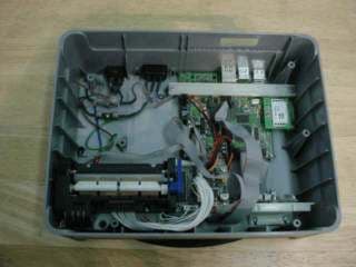
SJN-CL2-RFID-M1
Oct 05, 2006RFID Reader
Equipment Class
DXX - Part 15 Low Power Communication Device Transmitter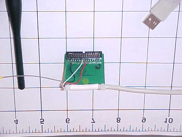
SJNVMX-100
Feb 08, 20052.4GHz Transmitter
Equipment Class
DSS - Part 15 Spread Spectrum Transmitter