SJNMRDXHandheld Radiation Detection Device
Visionary Products, Inc.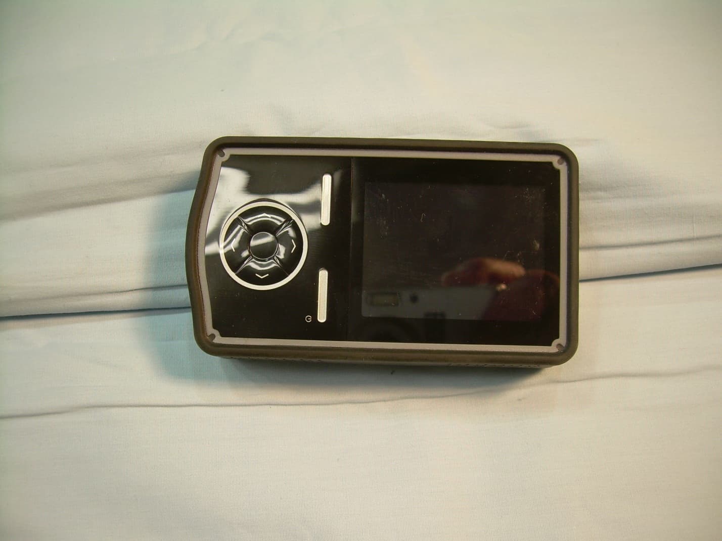
Click to zoom
Application Details
- Equipment Class
- DTS - Digital Transmission System
- Date of Grant
- Apr 21, 2014
- Application Purpose
- Original Equipment
- Date of Application
- Apr 21, 2014
- Equipment Note
- Handheld Radiation Detection Device
- Frequency Range
- 2405.00000000 - 2475.00000000
- Company
- Visionary Products, Inc.
- Country
- United States
Documents & Files
Document Text
Text extracted from the exhibit documents filed with the FCC. Open a document above to read the original.
Users Manual
INSTALLATION AND OPERATING INSTRUCTIONS FOR THE RADIATION DETECTION SYSTEM D-tect Systems Group Visionary Products Inc. 11814 South Election Road, Suite 200 Draper, UT 84020 www.dtectsystems.com Document Number: V024944_00AD_Mini_Rad-DX_Manual.docx Date: 4/4/2014 Page: 2 of 21 D-tect Systems • 11814 South Election Rd. Suite 200, Draper, UT 84020 • (801) 495-2310 • FAX (801) 495-2255 Table of Contents 1 Introduction ............................................................................................................................. 3 1.1 Key Features ................................................................................................................... 3 1.2 Version xx: Change Log ................................................................................................. 4 2 Getting Started ......................................................................................................................... 4 3 Specifications........................................................................................................................... 5 4 Box Contents ........................................................................................................................... 6 5 Software Options ..................................................................................................................... 7 5.1 DX-View Software ......................................................................................................... 7 5.2 DX-Dashboard Setup Tool ............................................................................................. 7 6 Maximizing Battery Life ......................................................................................................... 7 7 Recharging the MiniRad-DX ................................................................................................... 7 8 Stand-Alone Operation ............................................................................................................ 7 8.1 Communication Icons ..................................................................................................... 9 8.2 Main Menu Screen ........................................................................................................ 10 8.3 Device Menu ................................................................................................................. 11 8.4 GPS Menu ..................................................................................................................... 12 8.5 Alerts Menu .................................................................................................................. 13 8.5.1 Alarm Options .......................................................................................................... 13 8.5.2 Setting Alarm Levels ................................................................................................ 14 8.6 Display Menu ................................................................................................................ 14 8.6.1 Sleep Modes ............................................................................................................. 14 9 PC Connection and Network ................................................................................................. 16 10 Compliance Requirements ..................................................................................................... 18 11 Technical Support .................................................................................................................. 19 12 Warranty for D-tect System Products .................................................................................... 19 Document Number: V024944_00AD_Mini_Rad-DX_Manual.docx Date: 4/4/2014 Page: 3 of 21 D-tect Systems • 11814 South Election Rd. Suite 200, Draper, UT 84020 • (801) 495-2310 • FAX (801) 495-2255 1 Introduction The Mini Rad-DX is a handheld security and inspection device that detects emissions from radioactive material. The Mini Rad-DX system can operate as a stand-alone detector or as the roving detection part of a larger Mini Rad-DX and Rad-DX network for monitoring a building or facility. 1.1 Key Features Device Highlights • High sensitivity detector (CsI scintillator with PMT) • Operator selectable alarm levels (password controlled) • Two bright, high-resolution display screens • Real-time dose rate graph • Units displayed in rems per hour, Sieverts per hour, or counts per second • 130 hours between recharge (depending on options selected) • Integrated GPS for complete logging of dose rate, location, and time • Vibrate or audio alarm • ANSI N42.32, N42.33 and N42.42 compliant Mesh Network • Integrated mesh radio • 2.4 GHz, 25 selectable channels • Network range between devices is 1000m LOS • Up to 50 devices per network • Easy to set-up and modify network Communication and Security • Mini USB interface • 128 bit AES encryption With Network Integration • Real-time control and monitoring of an entire network via smartphone, PC, or tablet • Network can include Rad-DX area monitors and Rad-DXG portal monitors • Autologging – every time a MiniRad-DX comes within range of its DX network it will upload time, position, and alarm data –no user interaction required • Emails can be sent when an alarm occurs Document Number: V024944_00AD_Mini_Rad-DX_Manual.docx Date: 4/4/2014 Page: 4 of 21 D-tect Systems • 11814 South Election Rd. Suite 200, Draper, UT 84020 • (801) 495-2310 • FAX (801) 495-2255 1.2 Version xx: Change Log • TBD • TBD 2 Getting Started Additional documentation, such as Getting Started and Installation Guides, is available to help you setup your Mini Rad-DX network of detectors. Software is also available for configuration and communication including the DX-View software and the DX Cloud Server Software (DX- Dashboard). List of Quick Start and Installation Guides • Mini Rad-DX Handheld Radiation Detector Quick Start Guide** • R…
Text truncated - open the document above for the full version.
External Photos
Front View of the EUT Back View of the EUT View of the Top and Left Side of the EUT View of the Bottom and Right Side of the EUT
ID Label/Location Info
Mini Rad-DX Serial Number Label V02521801 SHEET 1 OF 1 SCALE: 1:1 REV DWG. NO. TITLE: DateDrawn Cog E Peer Prog Mgr QA 11814 South Election Rd Ste 200 Draper, UT 84020 PH# (801) 495-2310 FAX# (801) 495- 2255 engineeringengineering Refer artwork questions to: Gary Olsen VPI Engineering 801-495-2310 [email protected] Printing Instructions: Colors: Pantone Black Artwork is drawn to scale. Serial numbers to begin with 890000 Serial numbers to increment by one for each label (for example, 1st label serial number is 890000, 2nd label serial number is 890001, etc.) Bar code to be DataMatrix format Finished Label with Serial Number and Data Matrix Code Example Artwork Label Die Drawing white background DataMatrix code needs to contain this information 1.0” wide by 1.75” high label, 0.06” rounded corners DataMatrix Code Instructions: Data encoded in DataMatrix code to be the following: Example: V020738;890000 This portion will not change. The data in this portion must be included in every DataMatrix code. This portion is the serial number. It MUST increment and exactly match the serial number printed on each label. V020738;890000 FCC ID: SJNMRDX Part # V020738, dtectsystems.com This device complies with part 15 of the FCC Rules. Operation is subject to the following two conditions: (1) This device may not cause harmful interference, and (2) This device must accept any interference received, including interference that may cause undesired operation. FCC ID: SJNMRDX Part # V020738, dtectsystems.com This device complies with part 15 of the FCC Rules. Operation is subject to the following two conditions: (1) This device may not cause harmful interference, and (2) This device must accept any interference received, including interference that may cause undesired operation. S/N: 890000
Internal Photos
View of the EUT with Housing Opened View of the Top Side of the PCB View of the Bottom Side of the PCB View of the Front Side of the Display View of the Back Side of the Display
RF Exposure Info
The limits for Maximum Permissible Exposure (MPE) at different frequencies are set forth in C.F.R. 47 section 1.1307(b) and 1.1310(e). The limit for General Population / Uncontrolled Exposures for our frequency of 2.4GHz is set to be 1 mW/cm². The limit is compared to our device by measuring the Output Power for our frequency and calculating the Power Density according to the following formula: Power Density = (Power Out*Antenna Gain) / (4*π*r²) The product under test is the Mini Rad-DX which is produced by VPI Engineering for D-tect Systems. The Mini Rad-DX uses one antenna for the 802.15.4 transmitter. The gain of the antenna is 2.5dBi, which converts to a numeric gain of 1.78. The antenna will be placed a minimum of 10 mm away from a user and the device is assumed to be used under extremity exposure conditions. These measurements and calculations for the Mini Rad-DX 802.15.4 transmitter are listed in the table below: Channel Frequency MHz 802.15.4 Measured Output Power (mW) Power Density at r=1cm (mW/cm²) 11 2405 48.21 6.822228352 18 2440 39.73 5.622218055 25 2475 28.25 3.997675813 The device is qualified for an exemption under the Extremity Exposure Conditions as stated in section 4.2.3 in KDB 447498. In compliance with section 4.3.1 (1) the following 10-g SAR exclusion threshold is calculated – [max power of channel, mW/min test separation distance, mm]/[Square Root (Frequency)]. The calculated values are listed below and must be less than 7.5. Channel Frequency MHz 802.15.4 Measured Output Power (mW) SAR test Exclusion Threshold (must be < 7.5) 11 2405 48.21 7.476436892 18 2440 39.73 6.206024392 25 2475 28.25 4.444327494
Test Report
Nemko-CCL, Inc. 1940 West Alexander Street Salt Lake City, UT 84119 801-972-6146 Test Report Certification Test Of: mini Rad-DX FCC ID: SJNMRDX Test Specifications: FCC PART 15, Subpart C Test Report Serial No: 255821-3.1 Applicant: Visionary Products, Inc. 11814 South Election Road, Suite 200 Draper, UT 84020 U.S.A Dates of Test: March 31, 2014 and April 1, 2014 Report Issue Date: April 7, 2014 Accredited Testing Laboratory By: NVLAP Lab Code 100272-0 Nemko-CCL, Inc. TEST REPORT: 255821-3.1 REPORT ISSUE DATE: 04/07/2014 Page 2 of 56 TRF-15.247 DTS SUBC Issue 1 Jan 2014 CERTIFICATION OF ENGINEERING REPORT This report has been prepared by Nemko-CCL, Inc. to document compliance of the device described below with the requirements of Federal Communications Commission (FCC) Part 15, Subpart C. This report may be reproduced in full, partial reproduction may only be made with the written consent of the laboratory. The results in this report apply only to the sample tested. - Applicant: Visionary Products, Inc. - Manufacturer: VPI Manufacturing - Brand Name: D-tect Systems - Model Number: mini Rad-DX - FCC ID: SJNMRDX On this 7 th day of April 2014, I, individually and for Nemko-CCL, Inc., certify that the statements made in this engineering report are true, complete, and correct to the best of my knowledge, and are made in good faith. Although NVLAP has recognized that the Nemko-CCL, Inc. EMC testing facilities are in good standing, this report must not be used to claim product certification, approval, or endorsement by NVLAP, NIST, or any agency of the federal government. Nemko-CCL, Inc. Tested by: Norman P. Hansen Test Technician Reviewed by: Thomas C. Jackson General Manager Nemko-CCL, Inc. TEST REPORT: 255821-3.1 REPORT ISSUE DATE: 04/07/2014 Page 3 of 56 TRF-15.247 DTS SUBC Issue 1 Jan 2014 TABLE OF CONTENTS PAGE SECTION 1.0 CLIENT INFORMATION .................................................................................4 SECTION 2.0 EQUIPMENT UNDER TEST (EUT)..................................................................5 SECTION 3.0 TEST SPECIFICATION, METHODS & PROCEDURES .............................7 SECTION 4.0 OPERATION OF EUT DURING TESTING..................................................13 SECTION 5.0 SUMMARY OF TEST RESULTS ...................................................................14 SECTION 6.0 MEASUREMENTS AND RESULTS ...............................................................15 APPENDIX 1 TEST PROCEDURES AND TEST EQUIPMENT .........................................33 APPENDIX 2 PHOTOGRAPHS ................................................................................................38 Nemko-CCL, Inc. TEST REPORT: 255821-3.1 REPORT ISSUE DATE: 04/07/2014 Page 4 of 56 TRF-15.247 DTS SUBC Issue 1 Jan 2014 SECTION 1.0 CLIENT INFORMATION 1.1 Applicant: Company Name: Visionary Products, Inc. 11814 South Election Road, Suite 200 Draper, UT 84020 U.S.A Contact Name: Jeremy Williams Title: Engineer 1.2 Manufacturer: Company Name: VPI Manufacturing 11814 South Election Road, Suite 200 Draper, UT 84020 U.S.A Contact Name: Jason Stewart Title: Director of Manufacturing Nemko-CCL, Inc. TEST REPORT: 255821-3.1 REPORT ISSUE DATE: 04/07/2014 Page 5 of 56 TRF-15.247 DTS SUBC Issue 1 Jan 2014 SECTION 2.0 EQUIPMENT UNDER TEST (EUT) 2.1 Identification of EUT: Brand Name: D-tect Systems Model Number: mini Rad-DX Serial Number: V020738.890007 Dimensions: 62 mm x 31 mm x 107 mm 2.2 Description of EUT: The mini Rad-DX is a handheld security and inspection device that detects emissions from radioactive material. The mini Rad-DX system can operate as a stand-alone detector or as the roving detection part of a larger mini Rad-DX and Rad-DX network for monitoring a building or facility. The mini Rad-DX is powered by a 3.7 V Li-ion battery or over the mini USB port. Battery charging and communication with a host system may be made using the mini USB port. A Phihong PSM03A-050Q-3 power supply may be used for charging the battery. Communication with other devices is achieved using an 802.15.4, 2.4 GHz transceiver using Null RDC communications. The antenna is a Taoglas FXP73 flexible antenna with a manufacturer stated maximum gain of 2.5 dBi. The channels used by the 802.15.4 transceiver are shown in the table below. Channel Frequency (MHz) Channel Frequency (MHz) Channel Frequency (MHz) Channel Frequency (MHz) 11 2405 15 2425 19 2445 23 2465 12 2410 16 2430 20 2450 24 2470 13 2415 17 2435 21 2455 25 2475 14 2420 18 2440 22 2460 This report covers the circuitry of the devices subject to FCC Part 15, Subpart C. The circuitry of the device subject to FCC Subpart B was found to be compliant and is covered in Nemko-CCL, Inc. report 255821-2. Nemko-CCL, Inc. TEST REPORT: 255821-3.1 REPORT ISSUE DATE: 04/07/2014 Page 6 of 56 TRF-15.247 DTS SUBC Issue 1 Jan 2014 2.3 EUT and Support Equipment: The FCC ID numbers for all the EUT and support equipment used during the test are listed below: Brand Name Model Number Serial Number FCC ID Number or Compliance Description Name of Interface Ports / Interface Cables BN: D-tect Systems MN: mini Rad-DX (Note 1) SN: V020738.890007 SJNMRDX Radiation Detector See Section 2.4 BN: Samsung MN: N130 SN: ZLCM93HS900480X DoC Netbook Computer USB/USB A to mini USB cable (Note 2) Ethernet/Cat 5e cable BN: Trendnet MN: TE100-S8P SN: 0243C3A16540 DoC Network Switch LAN/Cat 5e cables Note: (1) EUT (2) Interface port connected to EUT (See Section 2.4) The support equipment listed above was not modified in order to achieve compliance with this standard. 2.4 Interface Ports on EUT: Name of Ports No. of Ports Fitted to EUT Cable Descriptions/Length Charge/Communication 1 Mini USB to USB A cable/1.75 meters 2.5 Modification Incorporated/Special Accessories on EUT: The following modifications were made to the EUT by the Client during testing to comply with the specification. This report is not complete without an accompanying signed attestation, that the product will have all …
Text truncated - open the document above for the full version.
Test Setup Photos
Front View Radiated Disturbance Worst Case Configuration Back View Radiated Disturbance Worst Case Configuration Front View Radiated Disturbance Configuration Using Netbook Host Back View Radiated Disturbance Configuration Using Netbook Host Front View Conducted Disturbance Worst Case Configuration Back View Conducted Disturbance Worst Case Configuration
Contact Information
Applicant
Jeremy Williams(Engineer)
Test Firm
Nemko-CCL incThomas Jackson
Technical Specifications
| # | Rule Parts | Frequency Range | Power Output |
|---|---|---|---|
| 1 | 15C | 2.40 GHz - 2.48 GHz | 27.10 mW |
Other Applications from Visionary Products, Inc.
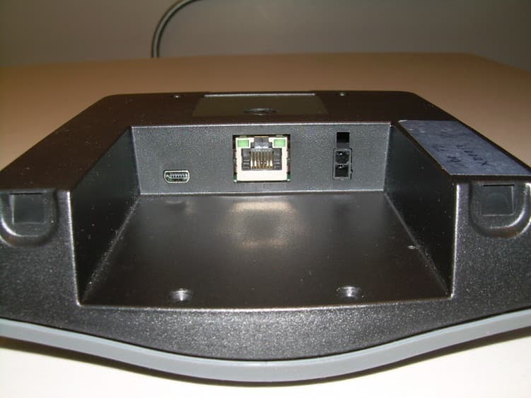
SJNRDX
Dec 05, 2012RADIATION DETECTION DEVICE
Equipment Class
DTS - Digital Transmission System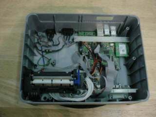
SJN-CL2-RFID-M1
Oct 05, 2006RFID Reader
Equipment Class
DXX - Part 15 Low Power Communication Device Transmitter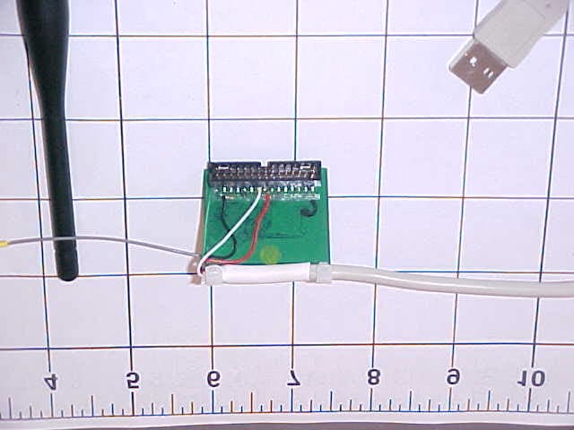
SJNVMX-100
Feb 08, 20052.4GHz Transmitter
Equipment Class
DSS - Part 15 Spread Spectrum Transmitter