SK2AUXXTR433.92MHz Wireless Transmitter/Receiver
COP Security System Corp.
Click to zoom
Application Details
- Equipment Class
- DSC - Part 15 Security/Remote Control Transmitter
- Date of Grant
- Nov 15, 2004
- Application Purpose
- Original Equipment
- Date of Application
- Nov 15, 2004
- Equipment Note
- 433.92MHz Wireless Transmitter/Receiver
- Frequency Range
- 433.92000000 - 433.92000000
- Company
- COP Security System Corp.
- Country
- Taiwan
Documents & Files
Document Text
Text extracted from the exhibit documents filed with the FCC. Open a document above to read the original.
Users Manual
FEDERAL COMMUNICATION COMMISSION INTERFERENCE STATEMENT This equipment has been tested and found to comply with the limits for a Class B digital device, pursuant to Part 15 of the FCC Rules. These limits are designed to provide reasonable protection against harmful interference in a residential installation. This equipment generates, uses and can radiate radio frequency energy and, if not installed and used in accordance with the instructions, may cause harmful interference to radio communications. However, there is no guarantee that interference will not occur in a particular installation. If this equipment does cause harmful interference to radio or television reception, which can be determined by turning the equipment off and on, the user is encouraged to try to correct the interference by one of the following measures: - Reorient or relocate the receiving antenna. - Increase the separation between the equipment and receiver. - Connect the equipment into an outlet on a circuit different from that to which the receiver is connected. - Consult the dealer or an experienced radio/TV technician for help. FCC Caution: Any changes or modifications not expressly approved by the party responsible for compliance could void the user’s authority to operate this equipment. This device complies with Part 15 of the FCC Rules. Operation is subject to the following two conditions: (1) This device may not cause harmful interference, and (2) this device must accept any interference received, including interference that may cause undesired operation. WIRELESS ZOOM CAMERA CONTROL BOX ITEM NO.: 15-AU15/25TR OVERVIEW 15-AU15/25T 15-AU15/25R FEATURES TRANSMITTER (15-AU15/25T) l Transmission frequency: 433.92MHz l 16 code setting l Transmission range: 300M in open area l 9V battery operation l Size: 141x50x30mm l Transmission Cycle 1 CYCLE l Duty Cycle: < 35% RECEIVER (15-AU15/25R) l Transmission frequency: 433.92MHz l Up to 16 set code available l Zoom In/Out control l Receiver range: 300M in open area l DC 12V operation l Size: 85x45x20mm DIAGRAM FUNCTION DEFINITION OF 15-AU15/25T NOTE: It has two function of 15-AU15/25T. One is Zoom In/Out function, another is for P/T/Z control. It will Structure 1 WIRE CONNECTION 1.25mm/4P FUNCTION COLOR ZOOM OUT ORANGE ZOOM IN BROWN +12V RED GND BLACK 1.2 Sec 5 Sec be used on Zoom In/Out function for 15-AU15/25R. Zoom In/Out function: It is no light of power indicator when push down button of / Near or / Far. P/T/Z control function: It is to shine of power indicator when push down button of / Near or / Far. REMARK: Press Lens button to change function. OPERATION INSTRUCTION 1. Set the dip switch at same code for 15-AU15/25T/R 2.Connect cable to the 15-AU15/25R and camera (see fig.) 3.Set 15-AU15/25T at Zoom In/Out function 4.Press button of / Tele or / Wide to Zoom In/Out. / Near Far / Power / Tele / Wide Auto Pan ON/OFF SPECIFICATION ITEMS 15-AU15/25R 15-AU15/25T Code Setting 16 Transmission frequency 433.92MHz Transmission range 300M in open area POWER SOURCE DC 12V DC 9V POWER CONSUMPTION 805mA 101mA DIMENSIONS L× W× Hmm 85×45×20 141×50×30 WEIGHT KG 60g 110g(include battery) PACKING Controller Receiver ×1 ×1 Cable Manual X1 X1 C-20040612 ?Power Indicator ?/ Tele ?/ Near ?Lens: Push button select function of Zoom In/Out function or P/T/Z control function ?/ Far ?/ Wide ?Auto Pan ON/ OFF:
Cover Letter(s)
Declaration To whom it may concern: 1. We have verified that there is no function when the user presses all of the buttons at the same time. 2. We perform the test for each one to research the highest transmit power. 3. The highest transmit power is occurring in press the “auto pan” button. 4. The accompany data is according to this test mode. Exclusive Certification Corporation Ivy Chen / Assistant
Cover Letter(s)
American Telecommunications Certification Body Inc. 6731 Whittier Ave, McLean, VA 22101 November 1, 2004 RE: COP Security System Corp FCC ID: SK2AUXTRX I have a few comments on this Application. Depending on your responses, kindly understand there may be additional comments. 1.) Kindly refer to my comment letter of October 18, 2004. Please note that items 6.) and 7.) do not seem to be addressed. Please provide written details of the ASK modulation pulse train. In addition, we need some information on the timing sequence of the pulse train in addition to what has been presented in the Test Report. It is necessary for us to determine if this product was tested in a “worst case” manner which would maximize it’s radiated field strength for comparison to the limits. William H. Graff President and Director of Engineering mailto: [email protected] The items indicated above must be submitted before processing can continue on the above referenced application. Failure to provide the requested information may result in application termination. Correspondence should be considered part of the permanent submission and may be viewed from the Internet after a Grant of Equipment Authorization is issued. Please do not respond to this correspondence using the email reply button. In order for your response to be processed expeditiously, you must submit your documents through the AmericanTCB.com website. Also, please note that partial responses increase processing time and should not be submitted. Any questions about the content of this correspondence should be directed to the sender.
Cover Letter(s)
American Telecommunications Certification Body Inc. 6731 Whittier Ave, McLean, VA 22101 October 18, 2004 RE: COP Security System Corp FCC ID: SK2AUXTRX I have a few comments on this Application. Depending on your responses, kindly understand there may be additional comments. 1.) The Manual does not have the “Information to User” statements required by 15.21. 2.) The External Photos are insufficient. Only one view is shown. 3.) The Internal Photographs are too small. Please provide larger, clearer photographs. 4.) The Schematics show what appear to be two complete circuits. Which one applies to this product? 5.) The Test Report in Section 5.5 identifies the RF module with an operating frequency of 499MHz. Is this correct? 6.) Kindly provide written details of the ASK modulation pulse train. Was it operating in a manner that produced the maximum “on” time? It is unclear from this filing if this device was set to it’s maximum transmit duty cycle. 7.) Does this device comply with the provisions of 15.231(a)(1) through (a)(4)? Kindly provide additional documentation addressing these concerns. 8.) You are making several references to ANSI C63.4 – 1992. Please be advised that that specification has been revised with a newer version. 9.) For the purposes of comparison with the limits, peak emission readings cannot be de-rated by more than 20dB. Several of your measurements show average values more than 20dB below the peak value. Kindly review your Test Report William H. Graff President and Director of Engineering mailto: [email protected] The items indicated above must be submitted before processing can continue on the above referenced application. Failure to provide the requested information may result in application termination. Correspondence should be considered part of the permanent submission and may be viewed from the Internet after a Grant of Equipment Authorization is issued. Please do not respond to this correspondence using the email reply button. In order for your response to be processed expeditiously, you must submit your documents through the AmericanTCB.com website. Also, please note that partial responses increase processing time and should not be submitted. Any questions about the content of this correspondence should be directed to the sender.
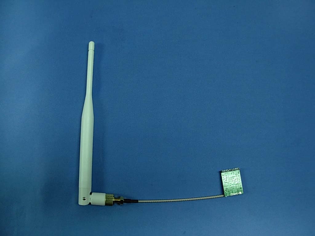
External Photos
External Photos
ID Label/Location Info
Model Number: 15-AU15/25TR 433.92MHz Wireless Transmitter FCC ID: SK2AUXXTR This device complies with Part 15 of the FCC reles. Operation is subjuct to the following two conditions: (1) This device may not cause harmful Interference. (2) This device must accept any Interference received Including Interference that may cause undesired operation This device complies with Part 15 of the FCC reles. Operation is subjuct to the following two conditions: (1) This device may not cause harmful Interference. (2) This device must accept any Interference received Including Interference that may cause undesired operation Size: 40*22 mm Transmitter Location:
Internal Photos
Internal Photos
Operational Description
Operation principle: The function is to control the focal length of camera, especially in zoom lens (zoom in and zoom out), in order to control the lens exactly; when the user release the switch, the data transmit will be stop immediately. Input data of four bits to the encoder of the transmitter, then convey to the receiver for the signal carrier of 433.92 with frequency. After the receiver accepts the code, decode the signal into the amplifier, enlarges the signal to relay to action. There are security codes for avoiding the possibility of duplicating codes in adjacent systems. The coding must be matching with the companion receiver. The transmitter emission after the user release the switch:
Test Report
1. Test Result and Data 1.1. Test Result of Radiated Emission Test Mode: X axis Test Date: Nov. 10, 2004 Temperature: 26 Humidity: 59% Atmospheric Pressure: 991 mbar a) Emission frequencies below 1 GHz Frequency (MHz) Ant-Pol H/V Meter Reading (dBuV) Corrected Factor (dB) Result@3m (dBuV/m) Limit@3m (dBuV/m) Margin (dB) Remark Table Deg. Ant High (m) *434.20 H 85.69 -8.23 77.46 100.8 -23.34 Peak 290 1.0 *434.20 H 72.54 -8.23 64.31 80.8 -16.48 Ave 290 1.0 867.80 H 38.33 1.85 40.18 80.8 -40.62 Peak 70 1.0 867.80 H 25.18 1.85 27.03 60.8 -33.77 Ave 70 1.0 *434.40 V 79.90 -8.23 71.67 100.8 -29.13 Peak 272 1.5 *434.40 V 66.75 -8.23 58.52 80.8 -21.48 Ave 272 1.5 867.70 V 33.39 1.85 35.24 80.8 -45.56 Peak 85 1.5 867.70 V 20.24 1.85 22.09 60.8 -38.71 Ave 85 1.5 b) Emission frequencies above 1 GHz Frequency (MHz) Ant-Pol H/V Meter Reading (dBuV) Corrected Factor (dB) Result@3m (dBuV/m) Limit@3m (dBuV/m) Margin (dB) Remark Table Deg. Ant High (m) 1724.5 H 52.88 -3.56 49.32 74 -24.68 Peak 166 1.5 1301.0 V 56.27 -6.39 49.89 74 -24.11 Peak 120 1.5 1735.0 V 57.56 -4.09 53.47 74 -20.53 Peak 145 1.0 2169.0 V 52.59 -2.05 50.55 74 -23.45 Peak 130 1.0 2603.0 V 51.17 -0.53 50.65 74 -23.35 Peak 180 1.0 NOTE: (1) Result@3m (dBuV/m)= Meter Reading (dBuV) + Correction Factor(dB) (2) Correction Factor(dB) = Antenna Factor (dB) + Cable Factor (dB) – Amplifier (dB) (3) The other emission levels were very low against the limit. (4) Margin = Result@3m – Limit value. (5) “” = Fundamental frequency (6) The average value of fundamental frequency is: Average = Peak value + 20log(Duty cycle) Where the duty factor is calculated from following formula: 20log (Duty cycle) = 20log = -13.15dB please see next page. 22ms 100ms
Test Report
Exclusive Certification Corp. Tel:886-2-2792-3366 Fax:886-2-2792-1100 Issued date: Oct. 05, 2004 1 of 21 FCC ID: SK2AUXXTR FCC Test Report: FI04091802-A FCC TEST REPORT according to FCC Part 15, Subpart C (15.231) / ANSI C63.4: 2001 † The test result refers exclusively to the test presented test model / sample., † Without written approval of Exclusive Certification Corp. the test report shall not be reproduced except in full. Applicant COP Security System Corp. Address 4-6F, NO.5, Lane 130, Min-Chung Rd., Hsin Tien City, Taipei Hsien, Taiwan, R.O.C. Equipment 433.92MHz Wireless Transmitter / Receiver Model No. 15-AU15/25TR FCC ID SK2AUXXTR Trade Name COP Security Exclusive Certification Corp. Tel:886-2-2792-3366 Fax:886-2-2792-1100 Issued date: Oct. 05, 2004 2 of 21 FCC ID: SK2AUXXTR FCC Test Report: FI04091802-A Contents 1. Report of Measurements and Examinations..................................................................................4 1.1. List of Measurements and Examinations............................................................................4 2. Test of Conducted Emission........................................................................................................5 3. Test of Radiated Emission...........................................................................................................6 3.1. Test Procedures................................................................................................................6 3.2. Typical Test Setup Layout of Radiated Emission.................................................................6 3.3. Limits of Radiated Emission...............................................................................................7 4. 20dB Occupied Bandwidth Measurement.....................................................................................8 4.1. Test Procedure.................................................................................................................8 4.2. Test Setup Layout.............................................................................................................8 4.3. Limits of Band Edges Measurement...................................................................................8 5. Test Configuration of Equipment under Test..................................................................................9 5.1. Test Mode and Test Software.............................................................................................9 5.2. Description of Test System................................................................................................9 5.3. Connection Diagram of Test System..................................................................................9 5.4. Feature of Equipment under Test.....................................................................................10 5.5. RF Module Specifications................................................................................................10 5.6. History of this test report.................................................................................................10 6. General Information of Test........................................................................................................11 7. Test Result and Data.................................................................................................................12 7.1. Test Result of Radiated Emission.....................................................................................12 7.2. 20dB Occupied Bandwidth Measurement.........................................................................13 8. List of Measuring Equipment Used.............................................................................................13 Appendix A. Photographs of EUT........................................................................ ...............A1 ~ A3 Exclusive Certification Corp. Tel:886-2-2792-3366 Fax:886-2-2792-1100 Issued date: Oct. 05, 2004 3 of 21 FCC ID: SK2AUXXTR FCC Test Report: FI04091802-A CERTIFICATE OF COMPLIANCE according to FCC Part 15, Subpart C (15.231) / ANSI C63.4: 2001 Applicant COP Security System Corp. Address 4-6F, NO.5, Lane 130, Min-Chung Rd., Hsin Tien City, Taipei Hsien, Taiwan, R.O.C. Equipment 433.92MHz Wireless Transmitter / Receiver Model No. 15-AU15/25TR FCC ID SK2AUXXTR I HEREBY CERTIFY THAT : The measurements shown in this test report were made in accordance with the procedures given in ANSI C63.4. The equipment was passed the test performed according to FCC Part 15, Subpart C (15.231) / ANSI C63.4: 2001. The test was carried out on Sep. 21, 2004 atExclusive Certification Corp. Signature Anson Chou / Manager Exclusive Certification Corp. Tel:886-2-2792-3366 Fax:886-2-2792-1100 Issued date: Oct. 05, 2004 4 of 21 FCC ID: SK2AUXXTR FCC Test Report: FI04091802-A 1. Report of Measurements and Examinations 1.1. List of Measurements and Examinations FCC Rule Test Type Result Remark 15.207 Conducted Emission N/A 9Vdc from batteries 15.209 15.231 Radiated Emission Pass Minimum Passing margin is -14.39dB at 434.20MHz 15.231 20 dB Occupied Bandwidth Measurement Pass Meet the requirement of limit Note: the information of measurement uncertainty is available upon the customer’s request. Test by: Exclusive Certification Corp. Tel:886-2-2792-3366 Fax:886-2-2792-1100 Issued date: Oct. 05, 2004 5 of 21 FCC ID: SK2AUXXTR FCC Test Report: FI04091802-A 2. Test of Conducted Emission N/A Exclusive Certification Corp. Tel:886-2-2792-3366 Fax:886-2-2792-1100 Issued date: Oct. 05, 2004 6 of 21 FCC ID: SK2AUXXTR FCC Test Report: FI04091802-A 3. Test of Radiated Emission 3.1. Test Procedures a. The EUT was placed on the top of a rotating table 0.8 meters above the ground at a 10 meter open area test site. The table was rotated 360 degrees to determine the position of the highest radiation. b. The EUT was set 3 meters away from the interference-receiving antenna, which was mounted on the top …
Text truncated - open the document above for the full version.
Test Setup Photos
Test Setup Photos
Contact Information
Applicant
Ian Yang(Assistant manager)
Technical Contact
COP Security System Corp.White Liu
[email protected]886-2-2218-0302
4-6F, NO.5 , Lane 130, Min-Chung Rd. · Hsin Tien City · Taiwan
Test Firm
Cerpass Technology CorporationAnson Chou
Technical Specifications
| # | Rule Parts | Frequency Range | Power Output |
|---|---|---|---|
| 1 | 15.231 | 433.92 MHz - 433.92 MHz | - |
Other Applications from COP Security System Corp.
SK22400DK
Jul 29, 20122.4GHz Digital Wireless A / V / Data Transceiver Module
Equipment Class
DSS - Part 15 Spread Spectrum Transmitter
SK2-2400RS
May 11, 20112.4G Wireless Data Transceiver
Equipment Class
DTS - Digital Transmission System