SLF-W226Wireless TV Speaker
Shenzhen Wanfengda Electronics Co., Ltd.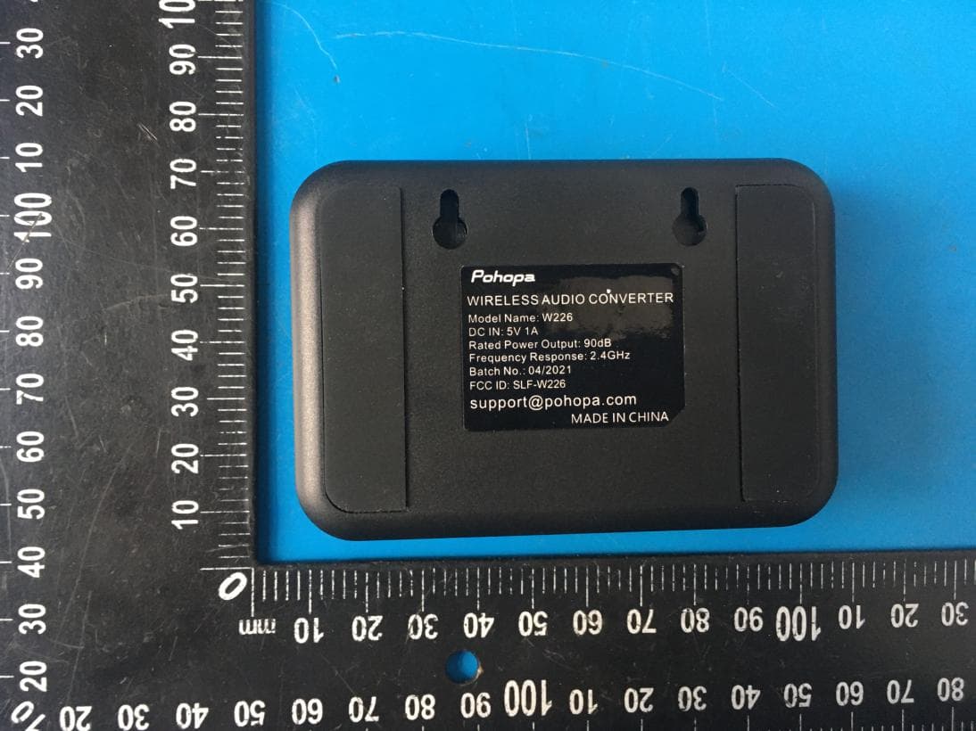
Click to zoom
Application Details
- Equipment Class
- DTS - Digital Transmission System
- Date of Grant
- May 02, 2021
- Application Purpose
- Original Equipment
- Date of Application
- May 02, 2021
- Equipment Note
- Wireless TV Speaker
- Frequency Range
- 2403.00000000 - 2478.00000000
- Country
- China
Documents & Files
Document Text
Text extracted from the exhibit documents filed with the FCC. Open a document above to read the original.
Users Manual
For Tech Support and Customer Services, please contact us via [email protected] TV jacks labeled TV jacks labeled EF-W226SPEAKER EF-W226SPEAKER What’s in the box Volume Down In any state, insert the micro USB cable, the speaker will be charging with red light on, filled with red light off. Speaker can be used while charging. 1, Can’t hear any sound from the speaker after connecting all the cables well. 2, Buzzing sound, continuous high pitch hum, sound cutting out, dropping put, tiny sound. 3, Does the Pohopa speaker mute the tv sound? Can others in my family hear TV while I use the Pohopa speaker? From marketing statistical analysis, if you experience no sound, sound cuts in and out, too much noises, most issues are caused by incorrect operation. Pls refer to the connect instructions or email to ([email protected]) with pictures of how you connect all the cables, we are confident to get one good solution for you within 24 hours. There are three audio cords included (optical, RCA and 3.5mm), in the end, only one of them is needed to complete installation. Please don't plug all of them at the same time. Ensure you set the TV or TV related AV device’s audio format to PCM/LPCM when you use digital optical connection For some TVs, you may have to activate the TV audio out by changing the TV’s AUDIO OUT setting to "External TV Speakers". Use your TV remote to go to the TV setting menu, select Audio and follow the instructions in your TV user manual. Not for TVs with non-functional audio out ports (test before purchase). Check if you can hear any sound by plugging a normal wired headphone directly into the TV audio out. Or check the quality of your Pohopa speaker through your iPad/PC etc. Question: Why both lights on transmitter and speaker flash in blue after connecting all the cables well and still can’t hear any sound from the speaker ? Answer: The speaker and the transmitter are already exclusively paired, so when you connect all the cables well as per the instructions, you will get the flashing blue light on speaker, while solid blue light on transmitter. If not, it means they disconnect somehow, you will have to get them paired first. Here is how: Turn on both speaker and transmitter, you will get both flashing blue lights. Press and hold the buttons at the same time till the blue light on speaker flashes quickly, and that is the time to press twice the power button(button labeled as “Pair”) on transmitter, then the flasing light on transmitter will go back to solid blue, which means they are paired again. And next time you use, they will always auto pair with each other, no need to do this again. Make sure you connect all the cables well, please refer to the three connection instructions and choose one suits your TV most. Place the transmitter as far as away from built-in Wi-Fi devices esp. Wi-Fi router to avoid interference, at least 16ft away. keep the distance between speaker and transmitter within 66ft.(might not be able to reach up to 100ft due to obstacles in the room) Please adjust the volume of TV TV related AV device (e.g., TV, cable box, STB) to a sufficient level, or raise the volume directly from the speaker volume control button. Speaker low battey, please charge the speaker. Please note speaker charing can Only Use 5V/1A Plug(Not included, regular phone plug is recommended). Step 2: Choose one of the three options below to connect the transmitter W126 with your TV. Step 1: Connect power supply to transmitter as picture shown on the right(The plug can not fully insert, which is normal). Then press and hold the power button on the top for 3 seconds to turn it on. (the blue light flashes after powered on) The plug can not fully insert Step 3: Connect W126 with W226 Warm tip: we recommend better to not turn power off to transmitter, very little power needed to keep on, so you don’t have to turn it on whenever you use. For digital optical connection, please set your TV audio output to PCM / LPCM, Dolby/DTS is not supported. The menus for sound out and audio format setting are not the same from different TV brands. please refer to your TV manual for details. (for ref.) Device homepage--system setting--image and sound--- voice setting--digital audio output--PCM/LPCM. For 3.5mm/AUX connection, normally no settings required, simplest way, highly recommendIf it does, please refer to the settings of Option 3. For RCA connection, make sure the RCA ports are labeled as "AUDIO OUT/OUTPUT/AV OUT", and set your TV audio output to external speakers. The menus for sound out and audio format setting are not the same from different TV brands. please refer to your TV manual for details. (for ref.) Menu - sound - speaker settings - external speakers - on. Press and hold the button for 2 seconds to turn on the speaker. The speaker will auto connect with the transmitter(you will get the flashing blue light on speaker, while solid blue light on transmitter when successfully connected), and you can hear the TV sound from the speaker. Warm tip:if you don't trun off the power to transmitter as we recommend, you can directly hear the TV sound coming out from the speaker each time you turn the speaker on. Option1: AUX cable Option2: Optical cable Option3: 3.5mm Female to 2RCA Male Audio Cable + AUX cable Option2 Option1 Product diagram Speaker charging IMPORTANT! Technical parameters Connect instructions DC IN 5V/1A Optical Digital Audio IN Audio IN Power/Pair Pause/Resume Sound/Pair Volume Up Micro USB Charging Slot Headset Jack Power ON/OFF X1 X1 W226TRANSMITTER W226TRANSMITTER Support Audio Format Optical Digital Audio Support Sampling Rate PCM/PLCM 32, 44.1, 48, 96 and 192kHz, and 24-bit X1 Micro USB Charging Cable X1AUX Cable X1 3.5mm Female to 2RCA Male Audio Cable 2.4G Wir eless Transmitting - Receiving System Troubleshooting List simplest way, highly recommend 4 5 6 783 AUDIO IN DC 5V OPTICAL IN /Pair X1AC Adapter X1Digital Optical Cable ① ② ③ AUDIO IN DC 5V OPTICAL IN /Pair /Pair ④ W226 DC 5…
Text truncated - open the document above for the full version.
Cover Letter(s)
4/23/2021 Equipment Autorisation Division Federal Communications Commission 7435 Oakland Mills Road Columbia, MD 21046 FCC ID: SLF-W226 Product Name: Wireless TV Speaker Request for Confidentiality Pursuant to Sections 0.457 and 0.459 of the commissions rules, we hereby request that the following documents be held confidential: Schematics Long-term confidential Block diagram Long-term confidential Operation description Long-term confidential These materials contain trade secrets and proprietary information and are not customarily released to the public. The public disclosure of this information might be harmful to the company and provide unjustified benefits to our competitors. Signature: Name huafeng Huang Position Engineer Company Name Shenzhen Wanfengda Electronics Co., Ltd Address 2F, Building 1, Hezhou Yuye Industrial Zone, Xixiang, Bao’an, Shenzhen, Guangdong, China, 518128. Tel +86-755-29617689 Fax / Email [email protected]
ID Label/Location Info
4.5cm 2.5cm 4.5cm Label Location FCC ID: SLF-W226 Shenzhen Wanfengda Electronics Co., Ltd Product name: Wireless TV Speaker Model No.: W226 This device complies with Part 15 of the FCC Rules. Operation is subject to the following two conditions: (1) this device may not cause harmful interference, and (2) this device must accept any interference received, including interference that may cause undesired operation.
RF Exposure Info
FCC ID: SLF-W226 RF Exposure evaluation According to 447498 D01 General RF Exposure Guidance v06 The 1-g and 10-g SAR test exclusion thresholds for 100 MHz to 6 GHz at test separation distances ≤ 50 mm are determined by: [(max. power of channel, including tune-up tolerance, mW)/(min. test separation distance, mm)] ·[√f(GHz)] ≤ 3.0 for 1-g SAR and ≤ 7.5 for 10-g extremity SAR, where f(GHz) is the RF channel transmit frequency in GHz Power and distance are rounded to the nearest mW and mm before calculation The result is rounded to one decimal place for comparison Worse case is as below: [2403MHz: 1.284dBm(1.34 mW) output power] (1.34 mW /5mm) ·[√2.403 (GHz)]= 0.42 <3.0 for 1-g SAR Then SAR evaluation is not required
Test Report
FCC TEST REPORT FCC ID: SLF-W226 On Behalf of Shenzhen Wanfengda Electronics Co., Ltd Wireless TV Speaker Model No.: W226 Prepared for : Shenzhen Wanfengda Electronics Co., Ltd Address : 2F, Building 1, Hezhou Yuye Industrial Zone, Xixiang, Bao’an, Shenzhen, Guangdong, China, 518128. Prepared By : Shenzhen Alpha Product Testing Co., Ltd. Address : Building i, No.2, Lixin Road, Fuyong Street, Bao’an District, 518103, Shenzhen, Guangdong, China Report Number : A2103115-C01-R02 Date of Receipt : March 17, 2021 Date of Test : March 17, 2021-April 21, 2021 Date of Report : April 22, 2021 Version Number : V0 Page 2 of 37 Report No.: A2103115-C01-R02 TABLE OF CONTENTS Description Page 1. Summary Of Standards And Results ................................................................................................... 6 1.1. Description of Standards and Results .......................................................................... 6 2. General Information .............................................................................................................................. 7 2.1. Description of Device (EUT) ....................................................................................... 7 2.2. Accessories of Device (EUT) ...................................................................................... 8 2.3. Tested Supporting System Details ............................................................................... 8 2.4. Block Diagram of connection between EUT and simulators ...................................... 8 2.5. Test Mode Description ................................................................................................. 8 2.6. Test Conditions ............................................................................................................ 8 2.7. Test Facility ................................................................................................................. 9 2.8. Measurement Uncertainty ............................................................................................ 9 2.9. Test Equipment List ................................................................................................... 10 3. Maximum Peak Output Power ........................................................................................................... 11 3.1. Limit .......................................................................................................................... 11 3.2. Test Procedure ........................................................................................................... 11 3.3. Test Setup ................................................................................................................... 11 3.4. Test Result ................................................................................................................. 11 4. Power Spectral Density ........................................................................................................................ 12 4.1. Limit .......................................................................................................................... 12 4.2. Test Procedure ........................................................................................................... 12 4.3. Test Setup ................................................................................................................... 12 4.4. Test Results ................................................................................................................ 12 5. Bandwidth ............................................................................................................................................. 14 5.1. Limit .......................................................................................................................... 14 5.2. Test Procedure ........................................................................................................... 14 5.3. Test Setup ................................................................................................................... 14 5.4. Test Result ................................................................................................................. 14 6. Spurious Emission ................................................................................................................................ 18 6.1. Test Limits ................................................................................................................. 18 6.2. Test Procedure ........................................................................................................... 18 6.3. Test Setup ................................................................................................................... 19 6.4. Test Results ................................................................................................................ 20 7. Band Edge Compliance ....................................................................................................................... 24 7.1. Block Diagram of Test Setup ..................................................................................... 24 7.2. Limit .......................................................................................................................... 24 7.3. Test Procedure ........................................................................................................... 24 7.4. Test Result ................................................................................................................. 24 8. Power Line Conducted Emissions ...................................................................................................... 27 8.1. Block Diagram of Test Setup ..................................................................................... 27 Page 3 of 37 Report No.: A2103115-C01-R02 8.2. Limit ............................................................…
Text truncated - open the document above for the full version.
Test Setup Photos
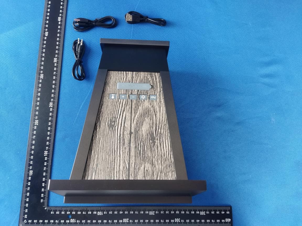
Test Setup Photo Photos of Radiated emission Photos of Conducted Emission test
Contact Information
Applicant
huafeng Huang(Engineer)
Test Firm
Shenzhen Alpha Product Testing Co., LTD.Simple Guan
[email protected]+86 755 29766001-810
Technical Specifications
| # | Rule Parts | Frequency Range | Power Output |
|---|---|---|---|
| 1 | 15C | 2.40 GHz - 2.48 GHz | 1.34 mW |
Other Applications from Shenzhen Wanfengda Electronics Co., Ltd.
SLFEF-B210S
Jul 08, 2024Outdoor Bluetooth Speakers
Equipment Class
DSS - Part 15 Spread Spectrum Transmitter
SLFEF-W280
May 02, 2021Powered Bookshelf Bluetooth and Wifi Speakers
Equipment Class
DSS - Part 15 Spread Spectrum Transmitter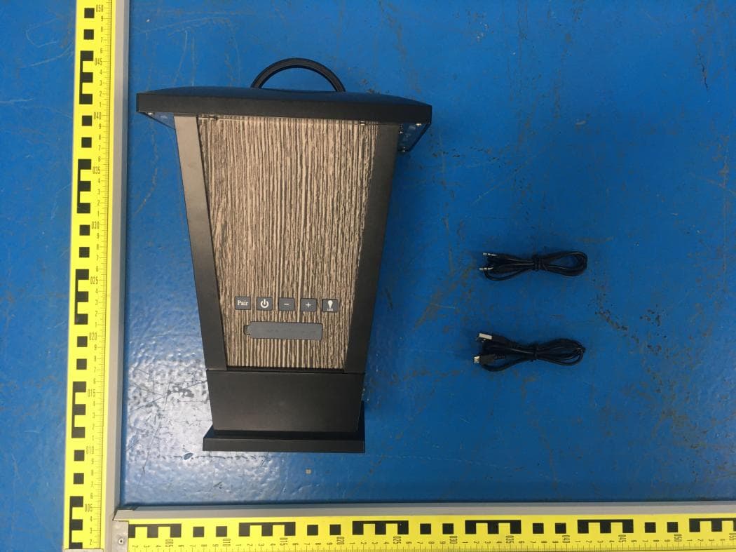
SLFEF-B210G
May 02, 2021Outdoor Bluetooth Speakers
Equipment Class
DSS - Part 15 Spread Spectrum Transmitter
SLFEF-B205
Apr 09, 2014Portable Mini Bluetooth Speaker
Equipment Class
DSS - Part 15 Spread Spectrum Transmitter
SLFEF-B202
Aug 17, 2013Bluetooth Speaker
Equipment Class
DSS - Part 15 Spread Spectrum Transmitter