SLY-WAPC11GCarrier Grade Embeddable Access Point
Control4 Corporation
Click to zoom
Application Details
- Equipment Class
- DTS - Digital Transmission System
- Date of Grant
- Oct 27, 2004
- Application Purpose
- Original Equipment
- Date of Application
- Oct 27, 2004
- Equipment Note
- Carrier Grade Embeddable Access Point
- Frequency Range
- 2412.00000000 - 2462.00000000
- Company
- Control4 Corporation
- Country
- United States
Documents & Files
Document Text
Text extracted from the exhibit documents filed with the FCC. Open a document above to read the original.
Users Manual
Pakedgedevice & Software co. 126 Clark Drive San Mateo, CA 94402 USA Tel: 650-773-0187 / Fax: 650-347-5138 FEDERAL COMMUNICATIONS COMMISSION DECLARATION OF CONFORMITY (DoC) For the following equipment: Product Name: Carrier Grade Embeddable Access Point Model Name: WAPC11g Trade Name: Pakedge is herewith confirmed to be in compliance with the requirements of ANSI C63.4 & FCC part 15 regulations. The test result has been shown in the ADT test report with number FD930904L01. And this compliance is subject to the following two conditions: (1) This device may not cause harmful interference and, (2) This device must accept any interference received, including interference that may cause undesired operation. The following local Manufacturer/Importer is responsible for this declaration: Pakedgedevice & Software co. (Company Name) 126 Clark Drive San Mateo, CA 94402 USA (Company Address) TEL: 650-773-0187 FAX : 650-347-5138 E-mail: [email protected] Victor Pak / President (Name) (Title) October 14, 2004 (Signature) (Date)
Users Manual
Wireless 802.11g AP User’s Manual Version 1.0 User’s Guide 1 Federal Communication Commission Interference Statement This equipment has been tested and found to comply with the limits for a Class B digital device, pursuant to Part 15 of the FCC Rules. These limits are designed to provide reasonable protection against harmful interference in a residential installation. This equipment generates, uses and can radiate radio frequency energy and, if not installed and used in accordance with the instructions, may cause harmful interference to radio communications. However, there is no guarantee that interference will not occur in a particular installation. If this equipment does cause harmful interference to radio or television reception, which can be determined by turning the equipment off and on, the user is encouraged to try to correct the interference by one of the following measures: - Reorient or relocate the receiving antenna. - Increase the separation between the equipment and receiver. - Connect the equipment into an outlet on a circuit different from that to which the receiver is connected. - Consult the dealer or an experienced radio/TV technician for help. FCC Caution: To assure continued compliance, any changes or modifications not expressly approved by the party responsible for compliance could void the user's authority to operate this equipment. This device complies with Part 15 of the FCC Rules. Operation is subject to the following two conditions: (1) This device may not cause harmful interference, and (2) this device must accept any interference received, including interference that may cause undesired operation. IMPORTANT NOTE: FCC Radiation Exposure Statement: This equipment complies with FCC radiation exposure limits set forth for an uncontrolled environment. This equipment should be installed and operated with minimum distance 20cm between the radiator & your body. This transmitter must not be co-located or operating in conjunction with any other antenna or transmitter. User’s Guide 2 Copyright Statement No part of this publication may be reproduced, stored in a retrieval system, or transmitted in any form or by any means, whether electronic, mechanical, photocopying, recording, or otherwise without the prior writing of the publisher. April. 2004 User’s Guide 3 Contents 1. Introduction ............................................................................................................... 4 2. Safety Notification .................................................................................................... 5 3. Hardware Installation................................................................................................ 6 4. Web Management Settings ...................................................................................... 7 4.1 Configuration............................................................................................................8 4.2 Local Area Network..................................................................................................9 4.3 Wireless.................................................................................................................11 4.4 Security..................................................................................................................14 4.5 Location Base Service............................................................................................16 4.6 Status Overview.....................................................................................................17 4.7 Diagnostic..............................................................................................................18 4.8 Upgrade Firmware.................................................................................................19 4.9 Reboot Access Point.............................................................................................20 4.10 Restore Factory Defaults.....................................................................................21 4.11 Configuration Profile Download.................................................................22 4.12 Configuration Profile Upload.....................................................................23 5. Appendix.................................................................................................................. 24 6. Troubleshooting ...................................................................................................... 25 User’s Guide 4 1. Introduction Thank you for purchasing your AP Wireless 802.11g AP. This user guide will assist you with the installation procedure. The package you have received should contain the following items: AP Wireless 802.11g AP Quick Installation Guide Power Supply / Cord Ethernet Cable CD Note: if anything is missing, please contact your vendor User’s Guide 5 2. Safety Notification Your Wireless AP should be placed in a safe and secure location. To ensure proper operation, please keep the unit away from water and other damaging elements. Please read the user manual thoroughly before you install the device. The device should only be repaired by authorized and qualified personnel. Please do not try to open or repair the device by yourself. Do not place the device in a damp or humid location, i.e. a bathroom. The device should be placed in a sheltered and non-slip location within a temperature range of +5 to +40 Celsius degree. Please do not expose the device to direct sunlight or other heat sources. The housing and electronic components may be damaged by direct sunlight or heat sources. User’s Guide 6 3. Hardware Installation Front Panel The front panel provides LED’s for device status. Refer to the following table for the meaning of each feature. LED STATUS Description Off No power Green On 1. Power on 2. Reset to default 3. Firmware upgrade (first 1 minute) POWER Green Blink 1. System up 2. Power on 3. Firmware upgrade Off No Ethe…
Text truncated - open the document above for the full version.
Cover Letter(s)
Pakedgedevice & Software co. 126 Clark Drive San Mateo, CA 94402 USA Tel: 650-773-0187 / Fax: 650-347-5138 FCC ID: SLY-WAPC11G Date: October 14, 2004 FEDERAL COMMUNICATIONS COMMISSION Authorization and Evaluation Division Confidentiality Request Pursuant to Sections 0.457 and 0.459 of the Commission’s Rules, the applicant hereby requests confidential treatment of information accompanying this application as outlined below: Schematics Block Diagram The above materials contain trade secrets and proprietary information not customarily released to the public. The public disclosure of these matters might be harmful to the applicant and provide unjustified benefits to its competitors. The applicant understands that pursuant to Rule 0.457, disclosure of this application and all accompanying documentation will not be made before the date of the grant for this application. Sincerely, Victor Pak / President Pakedgedevice & Software co. Tel: 650-773-0187 Fax: 650-347-5138 e-mail: [email protected]
Cover Letter(s)
Pakedgedevice & Software co. 126 Clark Drive San Mateo, CA 94402 USA Tel: 650-773-0187 / Fax: 650-347-5138 AGENCY AUTHORIZATION LETTER FCC ID: SLY-WAPC11G Date: October 14, 2004 To whom it may concern: We, the undersigned, hereby authorize Advance Data Technology Corp. (ADT) of Taiwan to act on our behalf, as our agent, in the following matters related to the FCC approval of our products: report submittal, related correspondence, the signing of all documents relating to these matters, and any other lawful activity necessary to obtain such certification. Any act carried out by ADT within the scope of this authorization shall have the same effects as our own. This authorization shall expire 6 months from original date. If you have any questions regarding the authorization, please don’t hesitate to contact us. Thank you. Sincerely, Victor Pak / President Pakedgedevice & Software co. Tel: 650-773-0187 Fax: 650-347-5138 e-mail: [email protected]
External Photos
Page 1 CONSTRUCTION PHOTOS OF EUT Page 2 Page 3 Page 4 Page 5 Page 6
ID Label/Location Info
FCC ID Label Location
ID Label/Location Info
pakedgedevice&software inc. IEEE 802.11g Compliant 2.4 GHz Frequency Band Model WAPC-11G www.pakedge.com This device complies with Part 15 of the FCC Rules. Operation is subject to the following two conditions: (1) This device may not cause harmful interference. and (2) this device must accept any interference received. Including interference that may cause undesired operations. Serial # : wapc-a-123456789 MAC : 000D88a227F7 FCC ID : SLY-WAPC11G L* W : 4. 5" * 1. 75"
Internal Photos
Page 7 Page 8 Page 9 Page 10 Page 11 Page 12 Page 13 Page 14 Page 15 Page 16 Page 17 Page 18 Page 19
Operational Description
FCC ID: SLY-WAPC11G Report No.: RF930904L01 Operational Description This device is a Carrier Grade Embeddable Access Point which operates in the 2.4GHz frequency spectrum with throughput of up to 54Mbps which OFDM technique will be applied. If the signal to noise radio is too poor which could not support 54Mbps, the 11Mbps data rate with CCK technique will be applied. The transmitter of the EUT is powered by Power over Ethernet. The antenna is Patch antenna with RSMA connector. The other instruction, please have a look at the users manual.
RF Exposure Info
FCC ID: SLY-WAPC11G Report No: SA930904L01 1 RF EXPOSURE REPORT REPORT NO.: SA930904L01 MODEL NO.: WAPC11g ACCORDING: FCC Guidelines for Human Exposure IEEE C95.1 APPLICANT: Pakedgedevice & Software co. ADDRESS: 126 Clark Drive San Mateo, CA 94402, U.S.A. ISSUED BY: Advance Data Technology Corporation TEST LOCATION: No. 19, Hwa Ya 2 nd Rd., Wen Hwa Tsuen, Kwei Shan Hsiang, Taoyuan Hsien 333, Taiwan, R.O.C. FCC ID: SLY-WAPC11G Report No: SA930904L01 2 RF Exposure Measurement (Mobile Device) 1. Introduction In this document, we try to prove the safety of radiation harmfulness to the human body for our product. The limit for Maximum Permissible Exposure (MPE) specified in FCC 1.1310 is followed. The Gain of the antenna used in this product is measured in a Fully Anechoic Chamber (FAC) calibrated for antenna measurement in ADT, and also the maximum total power input to the antenna is measured. Through the Friis transmission formula and the maximum gain of the antenna, we can calculate the distance, away from the product, where the limit of MPE is reached. Although the Friis transmission formula is a far field assumption, the calculated result of that is an over-prediction for near field power density. We will take that as the worst case to specify the safety range. 2. RF Exposure Limit According to FCC 1.1310: The criteria listed in the following table shall be used to evaluate the environmental impact of human exposure to radio-frequency (RF) radiation as specified in 1.1307(b) LIMITS FOR MAXIMUM PERMISSIBLE EXPOSURE (MPE) Frequency Range (MHz) Electric Field Strength (V/m) Magnetic Field Strength (A/m) Power Density (mW/cm 2 ) Average Time (minutes) (A)Limits For Occupational / Control Exposures 300-1500......F/3006 1500-100,000......56 (B)Limits For General Population / Uncontrolled Exposure 300-1500......F/15006 1500-100,000......1.030 F = Frequency in MHz FCC ID: SLY-WAPC11G Report No: SA930904L01 3 3. Friis Formula Friis transmission formula : Pd = (Pout*G) / (4*pi*r 2 ) where Pd = power density in mW/cm 2 Pout = output power to antenna in mW G = gain of antenna in linear scale Pi = 3.1416 R = distance between observation point and center of the radiator in cm If we know the maximum Gain of the antenna and the total power input to the antenna, through the calculation, we will know the MPE value at distance 20cm. Ref. : David K. Cheng, Field and Wave Electromagnetics, Second Edition, Page 640, Eq. (11-133). 4 EUT Operating condition The software provided by Manufacturer enabled the EUT to transmit and receive data at lowest, middle and highest channel individually. 5. Classification This device is not fixed inside the host equipment, it is connected with host through wire. So it is easy to be re-located in the place where at least 20cm far away from the body of the user. Warning statement to the user for keeping at least 20cm or more separation distance with the antenna should be included in users manual. So, this device is classified as Mobile Device. FCC ID: SLY-WAPC11G Report No: SA930904L01 4 6 Test Results 6.1 Antenna Gain The maximum Gain measured in Fully Anechoic Chamber is 8dBi or 6.309 (numeric). 6.2 Output Power Into Antenna & RF Exposure Distance: For 2.4GHz band: Channel Channel Frequency (MHz) Output Power to Antenna (mW) Power Density (mW/cm 2 ) Limit of Power Density (mW/cm 2 ) 1241231.9150.0401.0 6243732.3590.0411.0 11246231.8420.0401.0
Test Report
FCC ID: SLY-WAPC11G Report No.: RF930904L011Issued: Oct. 21, 2004 FCC TEST REPORT REPORT NO.: RF930904L01 MODEL NO.: WAPC11g RECEIVED: Sep. 04, 2004 TESTED: Sep. 09 ~ Sep. 21, 2004 APPLICANT: Pakedgedevice & Software co. ADDRESS: 126 Clark Drive San Mateo, CA 94402, U.S.A. ISSUED BY: Advance Data Technology Corporation LAB ADDRESS:No. 47, 14th Ling, Chia Pau Tsuen, Lin Kou Hsiang 244, Taipei Hsien, Taiwan, R.O.C. TEST LOCATION: No. 19, Hwa Ya 2 nd Rd., Wen Hwa Tsuen, Kwei Shan Hsiang, Taoyuan Hsien 333, Taiwan, R.O.C. This test report consists of 68 pages in total. It may be duplicated completely for legal use with the approval of the applicant. It should not be reproduced except in full, without the written approval of our laboratory. The client should not use it to claim product endorsement by CNLA, A2LA or any government agencies. The test results in the report only apply to the tested sample. 0528 ILAC MRA No. 2177-01 FCC ID: SLY-WAPC11G Report No.: RF930904L012Issued: Oct. 21, 2004 Table of Contents 1CERTIFICATION.........................................................................................................4 2SUMMARY OF TEST RESULTS................................................................................5 2.1MEASUREMENT UNCERTAINTY..............................................................................6 3GENERAL INFORMATION.........................................................................................7 3.1GENERAL DESCRIPTION OF EUT...........................................................................7 3.2DESCRIPTION OF TEST MODES.............................................................................8 3.3GENERAL DESCRIPTION OF APPLIED STANDARDS............................................8 3.4DESCRIPTION OF SUPPORT UNITS.......................................................................9 3.5CONFIGURATION OF SYSTEM UNDER TEST.....................................................10 4TEST TYPES AND RESULTS...................................................................................11 4.1CONDUCTED EMISSION MEASUREMENT............................................................11 4.1.1LIMITS OF CONDUCTED EMISSION MEASUREMENT.........................................11 4.1.2TEST INSTRUMENTS...............................................................................................11 4.1.3TEST PROCEDURES..............................................................................................12 4.1.4DEVIATION FROM TEST STANDARD....................................................................12 4.1.5TEST SETUP............................................................................................................13 4.1.6EUT OPERATING CONDITIONS.............................................................................14 4.1.7TEST RESULTS........................................................................................................15 4.2RADIATED EMISSION MEASUREMENT................................................................21 4.2.1LIMITS OF RADIATED EMISSION MEASUREMENT.............................................21 4.2.2TEST INSTRUMENTS..............................................................................................22 4.2.3TEST PROCEDURES..............................................................................................23 4.2.4DEVIATION FROM TEST STANDARD....................................................................23 4.2.5TEST SETUP............................................................................................................24 4.2.6EUT OPERATING CONDITIONS.............................................................................24 4.2.7TEST RESULTS........................................................................................................25 4.2.8TEST RESULTS (A)..................................................................................................26 4.2.9TEST RESULTS (B)..................................................................................................29 4.36dB BANDWIDTH MEASUREMENT........................................................................32 4.3.1LIMITS OF 6dB BANDWIDTH MEASUREMENT.....................................................32 4.3.2TEST INSTRUMENTS..............................................................................................32 4.3.3TEST PROCEDURE.................................................................................................33 4.3.4DEVIATION FROM TEST STANDARD....................................................................33 4.3.5TEST SETUP............................................................................................................33 4.3.6EUT OPERATING CONDITIONS.............................................................................33 4.3.7TEST RESULTS (A)..................................................................................................34 4.3.8TEST RESULTS (B)..................................................................................................38 FCC ID: SLY-WAPC11G Report No.: RF930904L013Issued: Oct. 21, 2004 4.4MAXIMUM PEAK OUTPUT POWER.......................................................................42 4.4.1LIMITS OF MAXIMUM PEAK OUTPUT POWER MEASUREMENT.......................42 4.4.2TEST INSTRUMENTS..............................................................................................42 4.4.3TEST PROCEDURES..............................................................................................43 4.4.4DEVIATION FROM TEST STANDARD....................................................................43 4.4.5TEST SETUP............................................................................................................43 4.4.6EUT OPERATING CONDITIONS.............................................................................43 4.4.7TEST RESULTS (A)...................................................…
Text truncated - open the document above for the full version.
Test Report
FCC ID: SLY-WAPC11G Report No.: RF930904L0146Issued: Oct. 21, 2004 4.5.3 TEST PROCEDURE The transmitter output was connected to the spectrum analyzer through an attenuator, the bandwidth of the fundamental frequency was measured with the spectrum analyzer using 3 kHz RBW and 30 kHz VBW, set sweep time=span/3kHz. The power spectral density was measured and recorded. The sweep time is allowed to be longer than span/3kHz for a full response of the mixer in the spectrum analyzer. 4.5.4 DEVIATION FROM TEST STANDARD No deviation 4.5.5 TEST SETUP 4.5.6 EUT OPERATING CONDITIONS Same as 4.3.6 EUTSPECTRUM ANALYZER FCC ID: SLY-WAPC11G Report No.: RF930904L0147Issued: Oct. 21, 2004 4.5.7 TEST RESULTS (A) EUT Carrier Grade Embeddable Access Point MODEL WAPC11g INPUT POWER (SYSTEM) 120 Vac, 60 Hz ENVIRONMENTAL CONDITIONS 24 deg. C, 64% RH, 991 hPa TESTED BYLeo Hung CHANNEL NUMBER CHANNEL FREQUENCY (MHz ) RF POWER LEVEL IN 3kHz BW (dBm) MAXIMUM LIMIT (dBm) PASS/FAIL 12412-8.818PASS 62437-8.468PASS 112462-8.398PASS FCC ID: SLY-WAPC11G Report No.: RF930904L0148Issued: Oct. 21, 2004 CH1 FCC ID: SLY-WAPC11G Report No.: RF930904L0149Issued: Oct. 21, 2004 CH6 FCC ID: SLY-WAPC11G Report No.: RF930904L0150Issued: Oct. 21, 2004 CH11 FCC ID: SLY-WAPC11G Report No.: RF930904L0151Issued: Oct. 21, 2004 4.5.8 TEST RESULTS (B) EUT Carrier Grade Embeddable Access Point MODEL WAPC11g INPUT POWER (SYSTEM) 120 Vac, 60 Hz ENVIRONMENTAL CONDITIONS 25 deg. C, 64% RH, 991 hPa TESTED BYLeo Hung CHANNEL NUMBER CHANNEL FREQUENCY (MHz ) RF POWER LEVEL IN 3KHz BW (dBm) MAXIMUM LIMIT (dBm) PASS/FAIL 12412-15.658PASS 62437-15.138PASS 112462-15.718PASS FCC ID: SLY-WAPC11G Report No.: RF930904L0152Issued: Oct. 21, 2004 CH1 FCC ID: SLY-WAPC11G Report No.: RF930904L0153Issued: Oct. 21, 2004 CH6 FCC ID: SLY-WAPC11G Report No.: RF930904L0154Issued: Oct. 21, 2004 CH11 FCC ID: SLY-WAPC11G Report No.: RF930904L0155Issued: Oct. 21, 2004 4.6 BAND EDGES MEASUREMENT 4.6.1 LIMITS OF BAND EDGES MEASUREMENT Below –20dB of the highest emission level of operating band (in 100kHz Resolution Bandwidth). 4.6.2 TEST INSTRUMENTS Description & ManufacturerModel No.Serial No.Calibrated Until SPECTRUM ANALYZERFSEK30100049Aug. 12, 2005 NOTE: The calibration interval of the above test instruments is 12 months and the calibrations are traceable to NML/ROC and NIST/USA. 4.6.3 TEST PROCEDURE The transmitter output was connected to the spectrum analyzer via a low lose cable. Set both RBW and VBW of spectrum analyzer to 100kHz with suitable frequency span including 100MHz bandwidth from band edge. The band edges was measured and recorded. 4.6.4 DEVIATION FROM TEST STANDARD No deviation 4.6.5 EUT OPERATING CONDITION Same as Item 4.3.6 FCC ID: SLY-WAPC11G Report No.: RF930904L0156Issued: Oct. 21, 2004 4.6.6 TEST RESULTS The spectrum plots are attached on the following 8 pages. D2 line indicates the highest level, D1 line indicates the 20dB offset below D2. It shows compliance with the requirement in part 15.247(C). 4.6.7 TEST RESULTS(A) NOTE: The band edge emission plot of CCK technique on the following 1~2 pages show 58.81dB delta between carrier maximum power and local maximum emission in restrict band (2.3735GHz). The emission of carrier strength list in the test result of channel 1 at the item 4.2.8 is 107.68dBuV/m, so the maximum field strength in restrict band is 107.68-58.81=48.87dBuV/m which is under 54dBuV/m limit. The band edge emission plot of CCK technique on the following 3~4 pages show 56.17dB delta between carrier maximum power and local maximum emission in restrict band (2.4999GHz). The emission of carrier strength list in the test result of channel 11 at the item 4.2.8 is 106.13dBuV/m, so the maximum field strength in restrict band is 106.13-56.17=49.96dBuV/m which is under 54dBuV/m limit. 4.6.8 TEST RESULTS(B) NOTE: The band edge emission plot of OFDM technique on the following 5~6 pages show 49.23dB delta between carrier maximum power and local maximum emission in restrict band (2.3900GHz). The emission of carrier strength list in the test result of channel 1 at the item 4.2.9 is 103.01dBuV/m, so the maximum field strength in restrict band is 103.01-49.23=53.78dBuV/m which is under 54dBuV/m limit. The band edge emission plot of OFDM technique on the following 7~8 pages show 49.75dB delta between carrier maximum power and local maximum emission in restrict band (2.4851GHz). The emission of carrier strength list in the test result of channel 11 at the item 4.2.9 is 100.89dBuV/m, so the maximum field strength in restrict band is 100.89-49.75=51.14dBuV/m which is under 54dBuV/m limit. FCC ID: SLY-WAPC11G Report No.: RF930904L0157Issued: Oct. 21, 2004 FCC ID: SLY-WAPC11G Report No.: RF930904L0158Issued: Oct. 21, 2004 FCC ID: SLY-WAPC11G Report No.: RF930904L0159Issued: Oct. 21, 2004 FCC ID: SLY-WAPC11G Report No.: RF930904L0160Issued: Oct. 21, 2004 FCC ID: SLY-WAPC11G Report No.: RF930904L0161Issued: Oct. 21, 2004 FCC ID: SLY-WAPC11G Report No.: RF930904L0162Issued: Oct. 21, 2004 FCC ID: SLY-WAPC11G Report No.: RF930904L0163Issued: Oct. 21, 2004 FCC ID: SLY-WAPC11G Report No.: RF930904L0164Issued: Oct. 21, 2004 FCC ID: SLY-WAPC11G Report No.: RF930904L0165Issued: Oct. 21, 2004 4.7 ANTENNA REQUIREMENT 4.7.1 STANDARD APPLICABLE For intentional device, according to FCC 47 CFR Section 15.203, an intentional radiator shall be designed to ensure that no antenna other than that furnished by the responsible party shall be used with the device. And according to FCC 47 CFR Section 15.247 (b), if transmitting antennas of directional gain greater than 6dBi are used, the power shall be reduced by the amount in dB that the directional gain of the antenna exceeds 6dBi. 4.7.2 ANTENNA CONNECTED CONSTRUCTION The antenna used in this product is Patch antenna with RSMA connector. And the maximum Gain of this antenna is 8dBi. FCC ID: SLY-WAPC11G Report No.: RF930904L0166Issued: Oct. 21, 2004 5 PHOTOGRAPHS OF THE TEST CONFIGURATION CONDUCTED EMISSION TEST FCC ID: SLY-WAPC11…
Text truncated - open the document above for the full version.
Test Setup Photos
FCC ID: SLY-WAPC11G Report No.: RF930904L0166Issued: Oct. 21, 2004 5 PHOTOGRAPHS OF THE TEST CONFIGURATION CONDUCTED EMISSION TEST FCC ID: SLY-WAPC11G Report No.: RF930904L0167Issued: Oct. 21, 2004 RADIATED EMISSION TEST
Contact Information
Applicant
Roger Midgley(Sr. Regulatory Compliance Engineer)
Technical Contact
Advance Data Technology CorporationEllis Wu
[email protected]+886-3-318-3232
No. 19 Hwa Ya 2nd rd. · Kueishan Taoyuan · Taiwan
Non-Technical Contact
Advance Data Technology CorporationEllis Wu
[email protected]+886-3-318-3232
Test Firm
Bureau Veritas CPS (H.K.) Ltd. Taoyuan BranchTommy Wu
Technical Specifications
| # | Rule Parts | Frequency Range | Power Output |
|---|---|---|---|
| 1 | 15C | 2.41 GHz - 2.46 GHz | 32.00 mW |
Other Applications from Control4 Corporation

SLY-WK1X22
Apr 13, 2015802.11ac Dual Band Access Point
Equipment Class
NII - Unlicensed National Information Infrastructure TX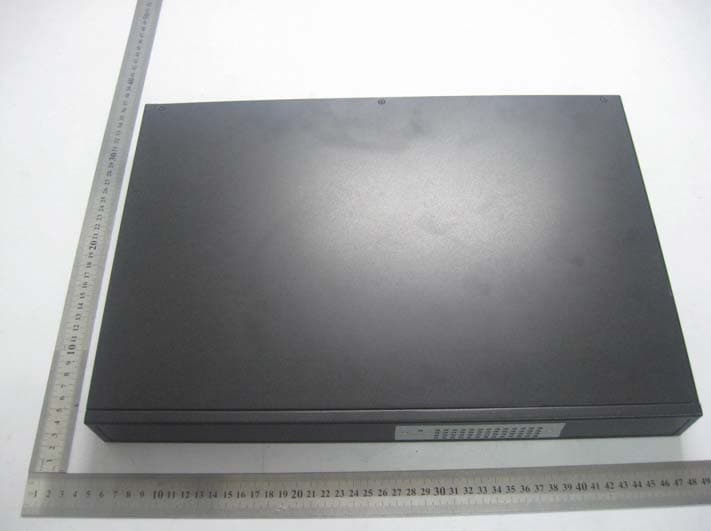
SLYSWXXXXPB
Oct 10, 2010NETWORKS SWITCH
Equipment Class
JBP - Part 15 Class B Computing Device Peripheral