SMCA33D Smart Projection TV
SHENZHEN HOLATEK CO.,LTD.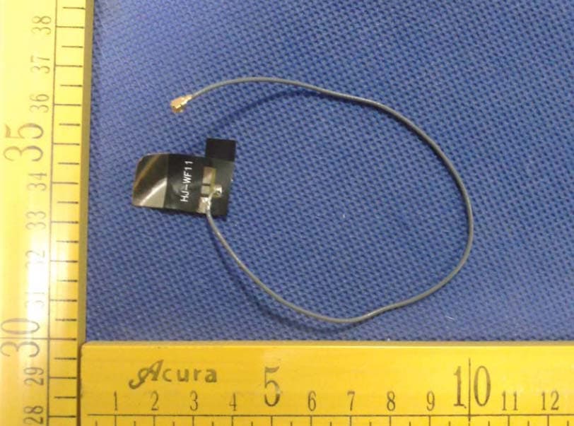
Click to zoom
Application Details
- Equipment Class
- DTS - Digital Transmission System
- Date of Grant
- Jan 20, 2014
- Application Purpose
- Original Equipment
- Date of Application
- Jan 20, 2014
- Equipment Note
- 3D Smart Projection TV
- Frequency Range
- 2402.00000000 - 2480.00000000
- Company
- SHENZHEN HOLATEK CO.,LTD.
- Country
- China
Documents & Files
Document Text
Text extracted from the exhibit documents filed with the FCC. Open a document above to read the original.
Users Manual
HOLATEK – A3 User Manual 3D LED Smart Projector & TV 3 Contents SAFETY INSTRUCTIONS ................................................................................................. 4 THE SAFETY SIGNS ........................................................................................................... 4 NOTICE FOR USE ............................................................................................................... 4 BATTERY INSTRUCTION .................................................................................................. 10 OPERATION INSTRUCTIONS ....................................................................................... 11 THE LIGHT SOURCE ................................................................................................. 11 OTHER INSTRUSTIONS ............................................................................................. 12 SUMMARY ......................................................................................................................... 14 PACKING LIST ............................................................................................................... 14 SYSTEM UPGRADE .......................................................................................................... 15 THE LOCATION AND FUNCTION OF CONTROL ........................................................ 16 EXTERNAL VIEW ........................................................................................................... 16 CONTROL AREA ............................................................................................................ 17 REAR VIEW ................................................................................................................... 18 BOTTOM VIEW ................................................................................................................ 19 FUNCTION OF REMOTE CONTROL .................................................................................... 20 PROJECTED IMAGES ..................................................................................................... 22 INSTALLATION OF THE PROJECTOR ................................................................................ 22 METHODS OF PROJECTION ............................................................................................ 24 BASIC OPERATIONS ...................................................................................................... 27 TURN ON AND TURN OFF THE PROJECTOR ...................................................................... 27 OPTION OF INFORMATION LANGUAGE ........................................................................... 29 OPTION OF INPUT SOURCE ............................................................................................. 29 KEYSTONE CORRECTION ............................................................................................... 29 USEAGE OF 3D FUNCTION............................................................................................. 30 USAGE OF SETTING OPTIONS ....................................................................................... 31 MAINTENANCE .............................................................................................................. 33 THE UNIT OF LIGHT SOURCE .......................................................................................... 33 INDICATOR ..................................................................................................................... 34 TROUBLESHOTTING ....................................................................................................... 34 SPECIFICATIONS .............................................................................................................. 35 4 Safety Instructions Thank you for purchasing the HOLATEK Projector. You need to read carefully the “safety instructions” before using it. After reading the User Manual, please keep it for future reference. The safety signs To ensure the safety of you and others and keep the items from damages, the User Manual applies a variety of signs whose meanings are as follows: Notice for use Caution ● Smoking, peculiar smell, hot temperature and other abnormal situations Please immediately stop using the machine (continuing using it will lead to dangers of causing fire and electric shock) if there is smoke, smell or any other abnormal situations, and please take the following measures: 1. Turn off the power of the machine; Danger This sign indicates that ignoring the sign and wrong operations will lead to death or serious injury. Caution This sign indicates that ignoring the sign and wrong operations will lead to the potential dangers of injury. Attention This sign indicates that ignoring the sign and wrong operations will lead to potential dangers of death or serious injury. 5 2. Unplug the power plug of the machine; 3. Contact your dealer or the HOLATEK authorized service center. ● Fault Please immediately stop using the machine (continuing using it will lead to dangers of causing fire and electric shock) if the picture display is abnormal or has any other abnormal phenomenon under correct operations, and please take the following measures: 1. Turn off the power of the machine; 2. Unplug the power plug of the machine; 3. Contact your dealer or the HOLATEK authorized service center. ● Power cord Improper use of power cord may lead to dangers of causing fire and electric shock, the user must observe the following precautions: The output voltage must be equal to rated AC voltage of the machines; A plethora of devices can not be inserted into the power socket to avoid overload The impaired power cord will lead to dangers of causing fire and electric shock, the user must observe the following precautions: Do not place heavy objects on the power cord or heat the power cord; Do not place the power cord between the wall and the table where the machine is pl…
Text truncated - open the document above for the full version.
Cover Letter(s)
SCS-F19: Confidentiality Request Letter Page 1 of 2 Rev 3.0 775 Montague Expressway Milpitas, CA 95035 Tel: 408-526-1188 Fax: 408-526-1088 Email: [email protected] Confidentiality Request Letter Revision History Reason for Amendment (current / obsolete) From To Approved Date Initial Release (obsolete) 1.0 1.0 Nov-14-2006 Adding CFR 2.459 (obsolete) 1.0 2.0 August – 11 - 2008 Updated company template & Added text box (current) 2.0 3.0 Jan-31-2012 SCS-F19: Confidentiality Request Letter Page 2 of 2 Rev 3.0 2014-01-13 To: Federal Communications Commission Authorization and Evaluation Division 7435 Oakland Mills Road Columbia, MD Subject: Permanent Confidentiality Request for FCC ID: SMCA3 We hereby request confidential treatment of information accompanying this application as outlined below: - Block Diagram - Schematics - Operational Description The above materials contain trade secrets and proprietary information not customarily released to the public. The public disclosure of these materials may be harmful to the applicant and provide unjustified benefits to its competitors. The applicant understands that pursuant to Section 0.457 & 0.459 of the Rules, disclosure of this application and all accompanying documentation will not be made before the date of the Grant for this application. Sincerely, Client’s signature Name: Alex Xiao Title : Manager Address: 16E-G Unit B,Honglong century plaza,NO.4002 shennan East Road,Luohu District, Shenzhen,China
Cover Letter(s)
Date:2014-01-14 FCC ID: SMCA3 Subject: Ad Hoc Mode Function Declaration To Whom it may concern, This device is acting as slave and operating in the 2.4 GHz WIFI:(2412 – 2462 MHz),BT: (2402 – 2480 MHz) band. Ad Hoc function is supported but not able to operate on non-US frequencies.Please contact the one signed below or the authorized agent for this filing. Thank you. Regards, Yours sincerely, Signatory Name: Alex Xiao Title : Manager Address: Rm.1001,Unit 4,Bld.B,Kexing Science Park, Keyuan Road, Nashan District, Shenzhen,China
External Photos
APPENDIX-PHOTOGRAPHS OF EUT CONSTRUCTIONAL DETAILS Photo 1 Photo 2 Photo 3 Photo 4 Photo 5 Photo 6
ID Label/Location Info
FCC ID LABELING AND LOCATION FCC ID Label 3D Smart Projection TV Model NO.: A3 HOLATEK FCC ID: SMCA3 SHENZHEN HOLATEK CO.,LTD. Made in China This device complies with part 15 of the FCC Rules. Operation is subject to the following two conditions: (1)This device may not cause harmful interference, and (2) this device must accept any interference received, including interference that may cause undesired operation. FCC ID Label Location The label shown shall be permanently affixed at a conspicuous location on the device and be readily visible to the user at the time purchase (Labeling requirements per 2.925)
Internal Photos
APPENDIX-PHOTOGRAPHS OF EUT CONSTRUCTIONAL DETAILS Photo 1 Photo 2 ANT Photo 3 Photo 4 Photo 5 Photo 6 Photo 7 Photo 8 Photo 9
RF Exposure Info
FCC §15.247 (i), §2.1091 – RF Exposure FCC ID:SMCA3 Applied procedures / limit According to FCC §15.247(i) and §1.1307(b)(1), systems operating under the provisions of this section shall be operated in a manner that ensures that the public is not exposed to radio frequency energy level in excess of the Commission’s guidelines. Limits for Occupational / Controlled Exposure Frequency Range (MHz) Electric Field Strength (E) (V/m) Magnetic Field Strength (H) (A/m) Power Density (S) (mW/ cm 2 ) Averaging Time |E| 2 ,|H| 2 or S (minutes) 0.3-3.0 614 1.63 (100)* 6 3.0-30 1842 / f 4.89 / f (900 / f)* 6 30-300 61.4 0.163 1.0 6 300-1500 F/300 6 1500-100,000 5 6 Note: ƒ is frequency in MHz * = Power density limit is applicable at frequencies greater than 100 MHz Limits for General Population / Uncontrolled Exposure Frequency Range (MHz) Electric Field Strength (E) (V/m) Magnetic Field Strength (H) (A/m) Power Density (S) (mW/ cm 2 ) Averaging Time |E| 2 ,|H| 2 or S (minutes) 0.3-1.34 614 1.63 (100)* 30 1.34-30 824/f 2.19/f (180/f)* 30 30-300 27.5 0.073 0.2 30 300-1500 F/1500 30 1500-100,000 1.0 30 Note: f = frequency in MHz * = Plane-wave equivalent power density MPE PREDICTION Predication of MPE limit at a given distance, Equation from OET Bulletin 65, Edition 97-01 Where: S = power density P = power input to antenna G = power gain of the antenna in the direction of interest relative to an isotropic radiator R = distance to the center of radiation of the antenna TEST RESULTS WIFI Mode Maximum peak output power (dBm) Output power to antenna (mW) Antenna Gain (numeric) Power Density (S) (mW/ cm 2 ) Limit of Power Density (S) (mW/ cm 2 ) Result 802.11b 15.68 36.98 1.58(2.0dBi) 0.0116 1 Pass 802.11g 13.72 23.55 1.58(2.0dBi) 0.0074 1 Pass 802.11n-HT20 12.68 18.54 1.58(2.0dBi) 0.0058 1 Pass 802.11n-HT40 10.43 11.04 1.58(2.0dBi) 0.0035 1 Pass BT4.0 Mode Maximum peak output power (dBm) Output power to antenna (mW) Antenna Gain (numeric) Power Density (S) (mW/ cm 2 ) Limit of Power Density (S) (mW/ cm 2 ) Result 1M -1.045 0.79 1.58(2.0dBi) 0.0002 1 Pass
Test Report
FCC RADIO TEST REPORT FCC ID: SMCA3 Product: 3D Smart Projection TV Trade Name: HOLATEK Model Name: A3 Serial Model: N/A Report No.: NTEK-2013NT1111727F1 Prepared for SHENZHEN HOLATEK CO.,LTD. 16E-G Unit B,Honglong century plaza,NO.4002 shennan East Road, Luohu District, Shenzhen,China Prepared by Shenzhen NTEK Testing Technology Co., Ltd. 1/F, Building E, Fenda Science Park, Sanwei Community, Xixiang Street Bao’an District, Shenzhen P.R. China Tel.: +86-0755-61156588 Fax.: +86-0755-61156599 Website:www.ntek.org.cn Page 2 of 65 Report No.: NTEK-2013NT1111727F1 TEST RESULT CERTIFICATION Applicant’s name........ SHENZHEN HOLATEK CO.,LTD. Address ........................ 16E-G Unit B,Honglong century plaza,NO.4002 shennan East Road,Luohu District, Shenzhen,China Manufacture's Name... SHENZHEN HOLATEK CO.,LTD. Address ........................ 16E-G Unit B,Honglong century plaza,NO.4002 shennan East Road,Luohu District, Shenzhen,China Product description Product name .................3D Smart Projection TV Model and/or type reference ..................... A3 Serial Model .................... N/A Standards.................... FCC Part15.247 Test procedure ................ ANSI C63.4-2003 This device described above has been tested by NTEK, and the test results show that the equipment under test (EUT) is in compliance with the FCC requirements. And it is applicable only to the tested sample identified in the report. This report shall not be reproduced except in full, without the written approval of NTEK, this document may be altered or revised by NTEK, personal only, and shall be noted in the revision of the document. Date of Test...................................... Date (s) of performance of tests ....... 11Nov. 2013 ~10 Jan. 2014 Date of Issue..................................... 10 Jan. 2014 Test Result......................................... Pass Testing Engineer : (Polo Cha) Technical Manager : (Brown Lu) Authorized Signatory : (Bovey Yang) Page 3 of 65 Report No.: NTEK-2013NT1111727F1 Table of Contents Page 1 . SUMMARY OF TEST RESULTS 5 1.1 TEST FACILITY 6 1.2 MEASUREMENT UNCERTAINTY 6 2 . GENERAL INFORMATION 7 2.1 GENERAL DESCRIPTION OF EUT 7 2.2 DESCRIPTION OF TEST MODES 9 2.3 BLOCK DIGRAM SHOWING THE CONFIGURATION OF SYSTEM TESTED 10 2.4 DESCRIPTION OF SUPPORT UNITS(CONDUCTED MODE) 11 2.5 EQUIPMENTS LIST FOR ALL TEST ITEMS 12 3 . EMC EMISSION TEST 13 3.1 CONDUCTED EMISSION MEASUREMENT 13 3.1.1 POWER LINE CONDUCTED EMISSION LIMITS 13 3.1.2 TEST PROCEDURE 14 3.1.3 DEVIATION FROM TEST STANDARD 14 3.1.4 TEST SETUP 14 3.1.5 EUT OPERATING CONDITIONS 14 3.1.6 TEST RESULTS 15 3.2 RADIATED EMISSION MEASUREMENT 17 3.2.1 RADIATED EMISSION LIMITS 17 3.2.2 TEST PROCEDURE 18 3.2.3 DEVIATION FROM TEST STANDARD 18 3.2.4 TEST SETUP 19 3.2.5 EUT OPERATING CONDITIONS 20 3.2.6 TEST RESULTS (BETWEEN 9KHZ – 30 MHZ) 21 3.2.7 TEST RESULTS (BETWEEN 30MHZ – 1GHZ) 22 3.2.8 TEST RESULTS (ABOVE 1000 MHZ) 23 4 . POWER SPECTRAL DENSITY TEST 36 4.1 APPLIED PROCEDURES / LIMIT 36 4.1.1 TEST PROCEDURE 36 4.1.2 DEVIATION FROM STANDARD 36 4.1.3 TEST SETUP 36 4.1.4 EUT OPERATION CONDITIONS 36 4.1.5 TEST RESULTS 37 5 . BANDWIDTH TEST 45 5.1 APPLIED PROCEDURES / LIMIT 45 5.1.1 TEST PROCEDURE 45 Page 4 of 65 Report No.: NTEK-2013NT1111727F1 Table of Contents Page 5.1.2 EUT OPERATION CONDITIONS 45 5.1.3 TEST RESULTS 46 6 . PEAK OUTPUT POWER TEST 54 6.1 APPLIED PROCEDURES / LIMIT 54 6.1.1 TEST PROCEDURE 54 6.1.2 DEVIATION FROM STANDARD 54 6.1.3 TEST SETUP 54 6.1.4 EUT OPERATION CONDITIONS 54 6.1.5 TEST RESULTS 55 7 . 100 KHZ BANDWIDTH OF FREQUENCY BAND EDGE 56 7.1 DEVIATION FROM STANDARD 56 7.2 TEST SETUP 56 7.3 EUT OPERATION CONDITIONS 56 7.4 TEST RESULTS 57 8 . ANTENNA REQUIREMENT 63 8.1 STANDARD REQUIREMENT 63 8.2 EUT ANTENNA 63 9 . EUT TEST PHOTO 64 APPENDIX-PHOTOGRAPHS OF EUT CONSTRUCTIONAL DETAILS Page 5 of 65 Report No.: NTEK-2013NT1111727F1 1. SUMMARY OF TEST RESULTS Test procedures according to the technical standards: FCC Part15 (15.247) , Subpart C Standard Section Test Item Judgment Remark 15.207 Conducted Emission PASS 15.247 (a)(2) 6dB Bandwidth PASS 15.247 (b) Peak Output Power PASS 15.247 (c) Radiated Spurious Emission PASS 15.247 (d) Power Spectral Density PASS 15.205 Band Edge Emission PASS 15.203 Antenna Requirement PASS NOTE: (1)” N/A” denotes test is not applicable in this Test Report Page 6 of 65 Report No.: NTEK-2013NT1111727F1 1.1 TEST FACILITY NTEK Testing Technology Co., Ltd Add.:1/F, Building E, Fenda Science Park, Sanwei Community, Xixiang Street, Bao’an District, Shenzhen P.R. China. FCC Registration No.:238937; IC Registration No.:9270A-1 CNAS Registration No.:L5516 1.2 MEASUREMENT UNCERTAINTY The reported uncertainty of measurement y ± U,where expended uncertainty U is based on a standard uncertainty multiplied by a coverage factor of k=2,providing a level of confidence of approximately 95 %。 No. Item Uncertainty 1 Conducted Emission Test ±1.38dB 2 RF power,conducted ±0.16dB 3 Spurious emissions,conducted ±0.21dB 4 All emissions,radiated(<1G) ±4.68dB 5 All emissions,radiated(>1G) ±4.89dB 6 Temperature ±0.5°C 7 Humidity ±2% Page 7 of 65 Report No.: NTEK-2013NT1111727F1 2. GENERAL INFORMATION 2.1 GENERAL DESCRIPTION OF EUT Equipment 3D Smart Projection TV Trade Name HOLATEK Model Name A3 Serial Model N/A Model Difference N/A Product Description The EUT is a 3D Smart Projection TV Operation Frequency: 802.11b/g/n(20MHz): 2412~2462MHz 802.11n(40MHz):2422~2452MHz Modulation Type: CCK/OFDM/DBPSK/DAPSK Bit Rate of Transmitter 802.11b:11/5.5/2/1 Mbps 802.11g:54/48/36/24/18/12/9/6Mbps 802.11n(20MHz):MSC7 802.11n(40MHz): MCS7 Number Of Channel 802.11b/g/n20MHz:11CH 802.11n40MHz:7CH Antenna Designation: Please see Note 3. Output Power(Conducted): 802.11b: 15.68 dBm (Max.) 802.11g: 13.72 dBm (Max.) 802.11n(20M): 12.68 dBm (Max.) 802.11n(40M): 10.43 dBm (Max.) Antenna Gain (dBi) 2.0dbi Based on the application, features, or specification exhibited in User's Manual, the EUT is considered as an ITE/Computing …
Text truncated - open the document above for the full version.
Test Report
FCC RADIO TEST REPORT FCC ID: SMCA3 Product: 3D Smart Projection TV Trade Name: HOLATEK Model Name: A3 Serial Model: N/A Report No.: NTEK-2013NT1111727F2 Prepared for SHENZHEN HOLATEK CO.,LTD. Rm.1001,Unit 4,Bld.B,Kexing Science Park, Keyuan Road, Nashan District, Shenzhen,China Prepared by Shenzhen NTEK Testing Technology Co., Ltd. 1/F, Building E, Fenda Science Park, Sanwei Community, Xixiang Street Bao’an District, Shenzhen P.R. China Tel.: +86-0755-61156588 Fax.: +86-0755-61156599 Website:www.ntek.org.cn Page 2 of 40 Report No.: NTEK-2013NT1111727F2 TEST RESULT CERTIFICATION Applicant’s name ........ SHENZHEN HOLATEK CO.,LTD. Address ........................ Rm.1001,Unit 4,Bld.B,Kexing Science Park, Keyuan Road, Nashan District, Shenzhen,China Manufacture's Name ... SHENZHEN HOLATEK CO.,LTD. Address ........................ Rm.1001,Unit 4,Bld.B,Kexing Science Park, Keyuan Road, Nashan District, Shenzhen,China Product description Product name .................3D Smart Projection TV Model and/or type reference ..................... A3 Serial Model .................... N/A Standards .................... FCC Part15.247 Test procedure ................ANSI C63.4-2003 This device described above has been tested by NTEK, and the test results show that the equipment under test (EUT) is in compliance with the FCC requirements. And it is applicable only to the tested sample identified in the report. This report shall not be reproduced except in full, without the written approval of NTEK, this document may be altered or revised by NTEK, personal only, and shall be noted in the revision of the document. Date of Test ...................................... Date (s) of performance of tests ....... 11Nov. 2013 ~10 Jan. 2014 Date of Issue ..................................... 10 Jan. 2014 Test Result ......................................... Pass Testing Engineer : (Polo Cha) Technical Manager : (Brown Lu) Authorized Signatory : (Bovey Yang) Page 3 of 40 Report No.: NTEK-2013NT1111727F2 Table of Contents Page 1 . SUMMARY OF TEST RESULTS 5 1.1 TEST FACILITY 6 1.2 MEASUREMENT UNCERTAINTY 6 2 . GENERAL INFORMATION 7 2.1 GENERAL DESCRIPTION OF EUT 7 2.2 DESCRIPTION OF TEST MODES 9 2.3 BLOCK DIGRAM SHOWING THE CONFIGURATION OF SYSTEM TESTED 10 2.4 DESCRIPTION OF SUPPORT UNITS(CONDUCTED MODE) 11 2.5 EQUIPMENTS LIST FOR ALL TEST ITEMS 12 3 . EMC EMISSION TEST 13 3.1 CONDUCTED EMISSION MEASUREMENT 13 3.1.1 POWER LINE CONDUCTED EMISSION LIMITS 13 3.1.2 TEST PROCEDURE 14 3.1.3 DEVIATION FROM TEST STANDARD 14 3.1.4 TEST SETUP 14 3.1.5 EUT OPERATING CONDITIONS 14 3.1.6 TEST RESULTS 15 3.2 RADIATED EMISSION MEASUREMENT 17 3.2.1 RADIATED EMISSION LIMITS 17 3.2.2 TEST PROCEDURE 18 3.2.3 DEVIATION FROM TEST STANDARD 18 3.2.4 TEST SETUP 19 3.2.5 EUT OPERATING CONDITIONS 20 3.2.6 TEST RESULTS (BETWEEN 9KHZ – 30 MHZ) 21 3.2.7 TEST RESULTS (BETWEEN 30MHZ – 1GHZ) 22 3.2.8 TEST RESULTS (ABOVE 1000 MHZ) 23 4 . POWER SPECTRAL DENSITY TEST 27 4.1 APPLIED PROCEDURES / LIMIT 27 4.1.1 TEST PROCEDURE 27 4.1.2 DEVIATION FROM STANDARD 27 4.1.3 TEST SETUP 27 4.1.4 EUT OPERATION CONDITIONS 27 4.1.5 TEST RESULTS 28 5 . BANDWIDTH TEST 30 5.1 APPLIED PROCEDURES / LIMIT 30 5.1.1 TEST PROCEDURE 30 Page 4 of 40 Report No.: NTEK-2013NT1111727F2 Table of Contents Page 5.1.2 EUT OPERATION CONDITIONS 30 5.1.3 TEST RESULTS 31 6 . PEAK OUTPUT POWER TEST 33 6.1 APPLIED PROCEDURES / LIMIT 33 6.1.1 TEST PROCEDURE 33 6.1.2 DEVIATION FROM STANDARD 33 6.1.3 TEST SETUP 33 6.1.4 EUT OPERATION CONDITIONS 33 6.1.5 TEST RESULTS 34 7 . 100 KHZ BANDWIDTH OF FREQUENCY BAND EDGE 35 7.1 DEVIATION FROM STANDARD 35 7.2 TEST SETUP 35 7.3 EUT OPERATION CONDITIONS 35 7.4 TEST RESULTS 36 8 . ANTENNA REQUIREMENT 38 8.1 STANDARD REQUIREMENT 38 8.2 EUT ANTENNA 38 9 . EUT TEST PHOTO 39 APPENDIX-PHOTOGRAPHS OF EUT CONSTRUCTIONAL DETAILS Page 5 of 40 Report No.: NTEK-2013NT1111727F2 1. SUMMARY OF TEST RESULTS Test procedures according to the technical standards: FCC Part15 (15.247) , Subpart C Standard Section Test Item Judgment Remark 15.207 Conducted Emission PASS 15.247 (a)(2) 6dB Bandwidth PASS 15.247 (b) Peak Output Power PASS 15.247 (c) Radiated Spurious Emission PASS 15.247 (d) Power Spectral Density PASS 15.205 Band Edge Emission PASS 15.203 Antenna Requirement PASS NOTE: (1)” N/A” denotes test is not applicable in this Test Report Page 6 of 40 Report No.: NTEK-2013NT1111727F2 1.1 TEST FACILITY NTEK Testing Technology Co., Ltd Add.:1/F, Building E, Fenda Science Park, Sanwei Community, Xixiang Street, Bao’an District, Shenzhen P.R. China. FCC Registration No.:238937; IC Registration No.:9270A-1 CNAS Registration No.:L5516 1.2 MEASUREMENT UNCERTAINTY The reported uncertainty of measurement y ± U,where expended uncertainty U is based on a standard uncertainty multiplied by a coverage factor of k=2,providing a level of confidence of approximately 95 %。 No. Item Uncertainty 1 Conducted Emission Test ±1.38dB 2 RF power,conducted ±0.16dB 3 Spurious emissions,conducted ±0.21dB 4 All emissions,radiated(<1G) ±4.68dB 5 All emissions,radiated(>1G) ±4.89dB 6 Temperature ±0.5°C 7 Humidity ±2% Page 7 of 40 Report No.: NTEK-2013NT1111727F2 2. GENERAL INFORMATION 2.1 GENERAL DESCRIPTION OF EUT Equipment 3D Smart Projection TV Trade Name HOLATEK Model Name A3 Serial Model N/A Model Difference N/A Product Description The EUT is a 3D Smart Projection TV Operation Frequency: 2402~2480MHz Modulation Type: GFSK Bit Rate of Transmitter 1 Mbps Number Of Channel 40CH Antenna Designation: Please see Note 3. Antenna Gain (dBi) 2.0dbi Based on the application, features, or specification exhibited in User's Manual, the EUT is considered as an ITE/Computing Device. More details of EUT technical specification, please refer to the User's Manual. Channel List Please refer to the Note 2. Ratings AC 100~240V,1200mA Adapter N/A Battery N/A Connecting I/O Port(s) Please refer to the User's Manual Note: 1. For a more detailed features description, please refer to the manufacturer’s specifications or th…
Text truncated - open the document above for the full version.
Test Setup Photos
Page 39 of 40 Report No.: NTEK-2013NT1111727F2 9. EUT TEST PHOTO Radiated Measurement Photos Page 40 of 40 Report No.: NTEK-2013NT1111727F2 Conducted Measurement Photos
Contact Information
Applicant
huayu yang
Test Firm
Shenzhen NTEK Testing Technology Co., Ltd.Jason Chen
Technical Specifications
| # | Rule Parts | Frequency Range | Power Output |
|---|---|---|---|
| 3 | 15C | 2.40 GHz - 2.48 GHz | 790.00 µW |
Other Applications from SHENZHEN HOLATEK CO.,LTD.

SMC-K610AO
Apr 29, 2026Smart Projector
Equipment Class
NII - Unlicensed National Information Infrastructure TX
SMC-K931AO
Feb 02, 2026Smart Projector
Equipment Class
NII - Unlicensed National Information Infrastructure TX
SMC-K970AO
Nov 18, 2025Smart Projector
Equipment Class
DTS - Digital Transmission System
SMC-V93
Aug 19, 2024Smart Projector
Equipment Class
DSS - Part 15 Spread Spectrum Transmitter
SMC-7K5
Jul 29, 2024Smart projector
Equipment Class
NII - Unlicensed National Information Infrastructure TX