SMK0112601AREMOTE CONTROL TRANSMITTER
Mr. Butler Company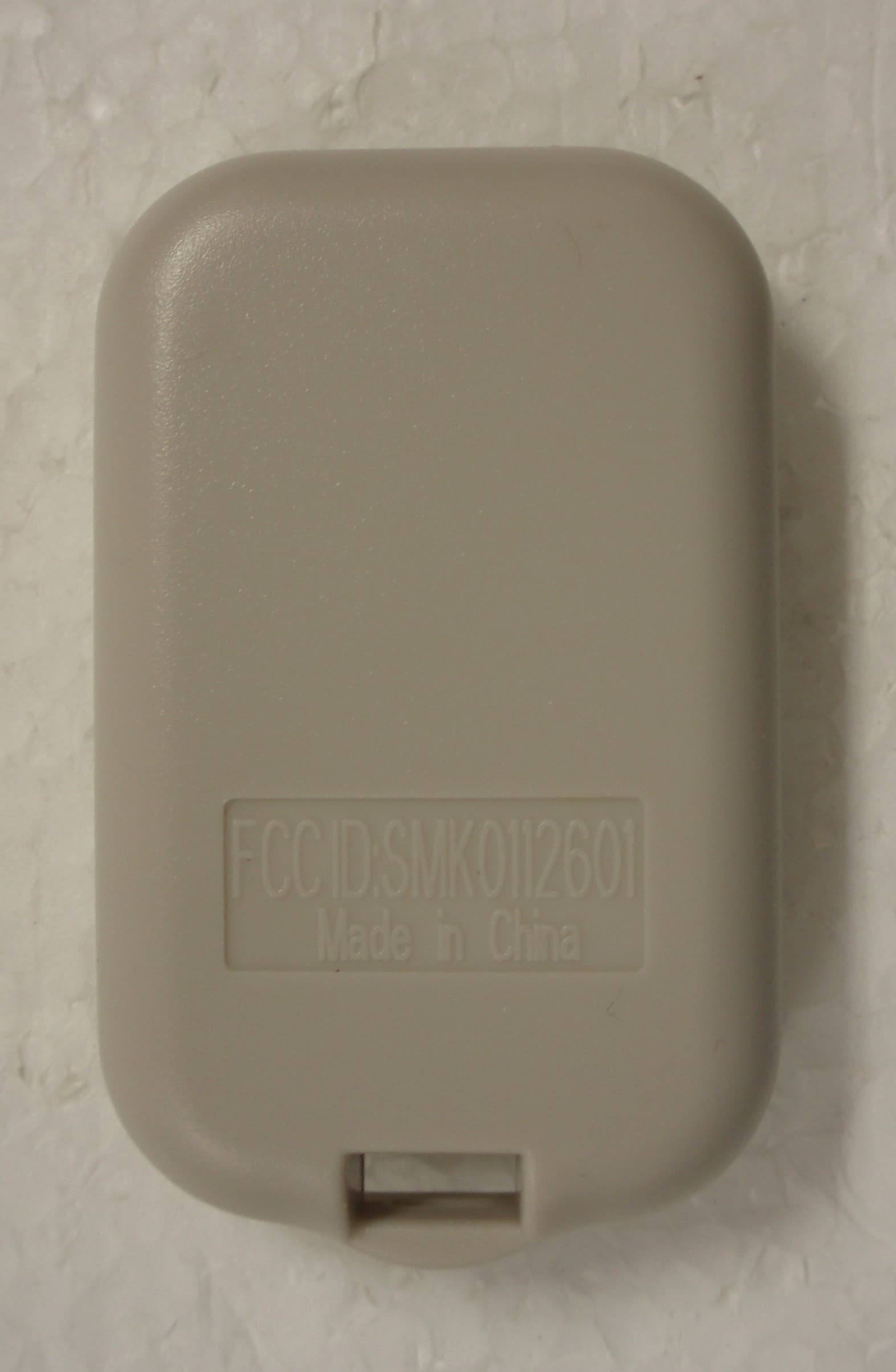
Click to zoom
Application Details
- Equipment Class
- DSC - Part 15 Security/Remote Control Transmitter
- Date of Grant
- Aug 29, 2012
- Application Purpose
- Original Equipment
- Date of Application
- Aug 29, 2012
- Equipment Note
- REMOTE CONTROL TRANSMITTER
- Frequency Range
- 433.92000000 - 433.92000000
- Company
- Mr. Butler Company
- Country
- United States
Documents & Files
Document Text
Text extracted from the exhibit documents filed with the FCC. Open a document above to read the original.
Users Manual
Box Remotizer Box Remotizer Box Lock Screw Left Door LockedLocked Right Door L positionR position Enjoy! INSTRUCTIONS: PARTS LIST Deadbolt latch must operate easily. (if not see reverse*). Pull Up Pull Apart D I S A S S E M B L Y Open door and lock deadbolt to begin. DO NOT REMOVE GUIDE Place base on box to make ready for one screw. Hold outside lock in place, OutsideInside Install base with one screw. Add next screw. -- Don’t over tighten! Slide splined stem proper end over tail piece of lock -- some locks di er. From inside, is door left or right? Set gearbox: Turn and keep turning gear until knob stops in position. With door LOCKED, slide black tip on to splined stem. (Left position shown) under guiding under top cap. Insert black bars (in tiny grooves) in both left and right sides of gearbox. Then slide bars down through holes as far as possible, and install 4 AA batteries.. Program Remotizer by pressing white button. Quickly press either button on remote. Hear 3 beeps. Slide cover down and remove handle guide. BaseExt. Bar Splined Stem GearboxBlack Bars ToolCoverRemote L R removing inside thumbturn. WHILE WHILE OR OR THEN + + - - 1. 5. 7. 8. 9. 10. 6. 2.3. 4. DO NOT REMOVE GUIDEDO NOT REMOVE GUIDE Turn LTurn R WARRANTY MR. BUTLER LLC WARRANTS TO THE ORIGINAL RESIDENTIAL USER OF THIS PRODUCT THAT IT WILL BE FREE FROM DEFECTS IN MATERIALS AND WORKMANSHIP, UNDER NORMAL USE, FOR ONE YEAR FROM THE DATE OF PURCHASE. USER MUST PROVIDE A COPY OF ORIGINAL PURCHASE RECEIPT. THIS WARRANTY DOES NOT COVER ABUSED OR MISUSED PRODUCTS. THIS WARRANTY DOES NOT APPLY TO UNITS THAT HAVE BEEN IMPROPERLY INSTALLED, MODIFIED, USED OTHER THAN DESIGNED, OR SUBJECTED TO ACTS OF GOD. **THIS WARRANTY IS LIMITED TO REPAIRING, REPLACING OR REFUNDING THE ORIGINAL PURCHASE PRICE AT THE DISCRETION OF MR. BUTLER LLC. MR. BUTLER LLC WILL NOT BE LIABLE FOR THE COST OF INSTALLING OR REMOVING THIS PRODUCT, NOR DIRECT, INDIRECT, OR CONSEQUENTIAL DAMAGE TO PERSONS OR PROPERTY RESULTING FROM THE USE OF THIS PRODUCT. TO USE THIS WARRANTY, ENCLOSE A COPY OF THE RECEIPT, TELEPHONE NUMBER, AND A CHECK OR MONEY ORDER OF $10.00 FOR SHIPPING AND HANDLING. RETURN FREIGHT PRE PAID TO: MR. BUTLER LLC 310 MORTON ST., SUITE #205 RICHMOND, TX 77469 USA ** OR PRODUCTS USED IN COMMERCIAL APPLICATIONS * If door is mis-aligned, make necessary adjustment to deadbolt strike and/or hole in the door jam. A hardware store man who knows locks, may show an easy way to make the adjustment. The manufacturer is not responsible for any radio or TV inerference caused by unauthorized modifications to this equipment. Such modifications vould void the user's authority to operate the equipment. TROUBLESHOOTING: - If Remotizer doesn’t beep or lock properly: Re-install and make sure you put it in LOCKED POSITION. - Also, make sure you positioned the knob by rotating the gear properly. This device complies with Part 15 of the FCC Rules. Operation is subject to the following two conditions: 1) This device may not cause harmful interference, and 2) This device must accept any interference received, including interference that may cause undesired operation. To prevent someone who has a transmitter from activating your Remotizer: 1. Pull off cover to Remotizer. 2. Press white button AND HOLD IN until you hear one loud beep (cleared). Now all remotes won’t work. 3. Program remote you want to use (up to 6 different remotes) per programming instructions on front page. VIEW INSTALLATION VIDEO AND ORDER ADDITIONAL REMOTES WWW.REMOTIZER.COM
External Photos
APPLICANT: MR. BUTLER COMPANY FCC ID: SMK0112601A
ID Label/Location Info
APPLICANT: MR. BUTLER COMPANY FCC ID: SMK0112601A LABEL SAMPLE FCC ID: SMK0112601A LABEL LOCATION
Internal Photos
APPLICANT: MR. BUTLER COMPANY FCC ID: SMK0112601A
Test Report
FCC PART 15.231 TEST REPORT LOW POWER UNLICENSED TRANSMITTER Applicant MR. BUTLER COMPANY Address 2634 YORKTOWN # 392 HOUSTON TX 77056 USA FCC ID SMK0112601A Product Description REMOTE CONTROL TRANSMITTER Date Sample Received 7/26/2012 Date Tested 7/28/2012 Tested By Nam Nguyen Approved By Mario R. de Aranzeta Timco Report No. 1859UT12TestReport.doc Test Results Pass Fail THE ATTACHED REPORT SHALL NOT BE REPRODUCED EXCEPT IN FULL WITHOUT THE WRITTEN APPROVAL OF TIMCO ENGINEERING, INC. Certificate #0955-01 849 NW STATE ROAD 45 NEWBERRY, FL 32669 USA PH: 888.472.2424 OR 352.472.5500 FAX: 352.472.2030 EMAIL: [email protected] HTTP://WWW.TIMCOENGR.COM APPLICANT: MR. BUTLER COMPANY FCC ID: SMK0112601A REPORT: M\Mr._Butler_Co\1859UT12\1859UT12TestReport.doc Page 2 of 15 mdea 09.20.2007 TABLE OF CONTENTS GENERAL REMARKS ...................................................................................................... 3 REPORT SUMMARY ....................................................................................................... 4 TEST ENVIRONMENT ..................................................................................................... 4 TEST SETUP................................................................................................................... 4 DUT SPECIFICATION ..................................................................................................... 5 MANUFACTURE DECLARATION OF COMPLIANCE WITH PART 15.231(A) ..................... 6 TEST EQUIPMENT LIST ................................................................................................. 7 TEST PROCEDURES ...................................................................................................... 8 RADIATION INTERFERENCE .......................................................................................... 9 CALCULATION OF DUTY CYCLE .................................................................................. 11 OCCUPIED BANDWIDTH .............................................................................................. 14 POWER LINE CONDUCTED INTERFERENCE ............................................................... 15 APPLICANT: MR. BUTLER COMPANY FCC ID: SMK0112601A REPORT: M\Mr._Butler_Co\1859UT12\1859UT12TestReport.doc Page 3 of 15 mdea 09.20.2007 GENERAL REMARKS The attached report shall not be reproduced except in full without the written permission of Timco Engineering Inc. Summary The device under test does: fulfill the general approval requirements as identified in this test report not fulfill the general approval requirements as identified in this test report Attestations This equipment has been tested in accordance with the standards identified in this test report. To the best of my knowledge and belief, these tests were performed using the measurement procedures described in this report. All instrumentation and accessories used to test products for compliance to the indicated standards are calibrated regularly in accordance with ISO 17025 requirements. Certificate # 0955-01 I attest that the necessary measurements were made, under my supervision, at: Timco Engineering Inc. 849 NW State Road 45 Newberry, Fl 32669 Authorized Signatory Name: Mario de Aranzeta C.E.T. Compliance Engineer/ Lab. Supervisor Date: July/27/2012 APPLICANT: MR. BUTLER COMPANY FCC ID: SMK0112601A REPORT: M\Mr._Butler_Co\1859UT12\1859UT12TestReport.doc Page 4 of 15 mdea 09.20.2007 REPORT SUMMARY Disclaimer The test results only relate to the item tested. Applicable Rule(s) FCC Pt 15.231, Pt 15.209, Pt 15.207, ANSI C63.4: 2003 TEST ENVIRONMENT Test Facility The test sites are located at 849 NW State Road 45 Newberry, FL 32669 USA. Test Condition: Temperature: 26ºC Relative humidity: 50% TEST SETUP Test Exercise (e.g software description, test signal, etc.): The DUT was placed in continuous transmit mode of operation. Deviation from the standard(s) No deviation from the standard(s) Modification to the DUT: No modification was made to the DUT. Supporting Peripheral Equipment Not applicable. The device is a stand-alone remote control radio. APPLICANT: MR. BUTLER COMPANY FCC ID: SMK0112601A REPORT: M\Mr._Butler_Co\1859UT12\1859UT12TestReport.doc Page 5 of 15 mdea 09.20.2007 DUT SPECIFICATION Applicant MR. BUTLER COMPANY Description REMOTE CONTROL TRANSMITTER FCC ID SMK0112601A Frequency Range 433.97 MHz DUT Power Source 110–120Vac/50– 60Hz DC Power Battery Operated Exclusively Test Item Prototype Pre-Production Production Type of Equipment Fixed Mobile Portable APPLICANT: MR. BUTLER COMPANY FCC ID: SMK0112601A REPORT: M\Mr._Butler_Co\1859UT12\1859UT12TestReport.doc Page 6 of 15 mdea 09.20.2007 MANUFACTURE DECLARATION OF COMPLIANCE WITH PART 15.231(A) Item Description Yes No 1 Does this device transmit a signal that is only used to control another device? x 2 Does this device send data with this control signal? x 3 Does this device send data? Data is, things like: temperature, wind direction, fluid amount, rate of flow, etc. x 4 Does this device transmit continuously or automatically? x 5 If manually operated does this device stop transmitting within 5 seconds of releasing the button? x 6 If automatically operated does it deactivate 5 seconds after activation? 7 Does it transmit at regular predetermined intervals? x 8 Does it poll or send supervisory information? x If yes does it do a system integrity check? How often? 9 Is this a fire, security or safety of life device? x If YES does the device stop transmitting after the alarm condition is satisfied? 10 Duty cycle: Maximum on-time? x If YES, on-time in 100 ms? If Other, please specify here 72.6 On time in 11 Modulation technique: Please specify the modulation of the test sample, FM, or AFSK, or FSK, or on-off keying, or others? OOK APPLICANT: MR. BUTLER COMPANY FCC ID: SMK0112601A REPORT: M\Mr._Butler_Co\1859UT12\1859UT12TestReport.doc Page 7 of 15 mdea 09.20.2007 TEST EQUIPMENT LIST Device Manufacturer Model Serial Number Ca…
Text truncated - open the document above for the full version.
Contact Information
Applicant
Mark Kilbourne(President)
Test Firm
Timco Engineering, Inc.Bruno Clavier
Technical Specifications
| # | Rule Parts | Frequency Range | Power Output |
|---|---|---|---|
| 1 | 15.231 | 433.92 MHz - 433.92 MHz | - |
Other Applications from Mr. Butler Company
SMK0112601
Oct 15, 2006TRANSMITTER
Equipment Class
DSC - Part 15 Security/Remote Control Transmitter
SMK011260
Mar 07, 2005KEYLESS ENTRY SYSTEM
Equipment Class
DSC - Part 15 Security/Remote Control Transmitter