SNKHNET50Wireless Power Usage Monitoring System
ConectiSys Corporation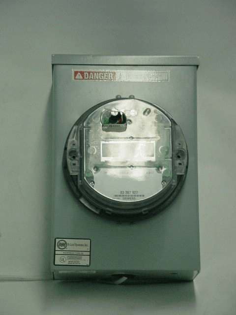
Click to zoom
Application Details
- Equipment Class
- DSS - Part 15 Spread Spectrum Transmitter
- Date of Grant
- Nov 21, 2004
- Application Purpose
- Original Equipment
- Date of Application
- Nov 21, 2004
- Equipment Note
- Wireless Power Usage Monitoring System
- Frequency Range
- 902.40000000 - 927.60000000
- Company
- ConectiSys Corporation
- Country
- United States
Documents & Files
Document Text
Text extracted from the exhibit documents filed with the FCC. Open a document above to read the original.
Users Manual
ConectiSys HNET 5.0 Installation and Operations Manual Sections: I. FCC Warning and Compliance Statement II. Radio and antenna installation into power meter. III. Meter installation. IV. Meter unit operation. V. Reference Figures. I. FCC Warning and Compliance Statement FCC Warning The users manual or instruction manual for an intentional or unintentional radiator shall caution the user that changes or modifications not expressly approved by the party responsible for compliance (ConectiSys) could void the user's authority to operate the equipment. FCC Compliance Statement This device complies with Part 15 of the FCC Rules. Operation is subjected to the following two conditions 1) this device may not cause harmful interference and 2) this device must accept any interference received, including interference that may cause undesired operation. II. Radio and antenna installation into power meter Introduction: HNET 5.0’s radio system was designed to be integrated into a Siemens Altimus 240v 60Hz Solid State Electricity Meter or equivalent for wireless power usage monitoring. The radio module consists of three PCB assemblies (power supply, controller module and RF module) and an antenna. The power supply consists of a 240VAC to 3.3VDC converter with external wire interfaces to the power meter (for AC input) and to the controller module (for DC output). The controller module and RF modules interface together via PCB mounted headers. The controller is interfaced to the meter PCB via optically coupled serial data lines. The dipole antenna is mounted inside of the meter along the bottom side of the meter faceplate. Page 1 of 5 Installation: Note: Before radio installation has begun, it is assumed the radio module (consisting of power supply, controller module and RF module) has already been assembled and tested in accordance with the manufacturer’s acceptance test procedure. See Figure 1. 1. Connect the AC input cable between power supply and meter PCB. (See Figure 2a and 2b.) 2. Connect controller module data interface cable to meter PCB. (See Figure 2a.) 3. Set radio into meter housing and install mounting screws. Ensure that no cables are crimped or physically interfering with the meter PCB or radio modules. (See Figure 3.) 4. Connect controller module data interface cable to controller module. (See Figure 3.) 5. Mount antenna along bottom side of meter faceplate. Antenna elements should be flat up against meter faceplate. (See Figure 4.) 6. Connect antenna coax cable from MMCX connector on antenna PCB to MMCX connector on RF module. Cable should be run on the right side of the meter and between the RF and controller modules. 7. Install meter assembly onto meter back-plate and insert locking tabs. Ensure coax and cables are not crimped or physically interfering with meter assembly. III. Meter Installation: Assembled meter unit is to be installed on an appropriate meter box by authorized utility company personnel in accordance with all safety precautions and procedures. IV. Meter Unit Operation: Meter assemblies with installed radio modules are non-user controlled wireless monitoring devices and need no direct end-user setup or intervention. Wireless meter units are remotely controlled by a base-station not described in this document. Page 2 of 5 V. Reference Figures. Figure 1 – Radio Module Figure 2a – AC and Data Input Cables Page 3 of 5 Figure 2b – AC Input Cable Figure 3 – Radio Mounting Page 4 of 5 Figure 4 – Antenna Mounting Page 5 of 5
Cover Letter(s)
ConectiSys CORPORATION 11 November 2004 American Telecommunications Certification Body, Inc. 6731 Whittier Avenue Suite C110 McLean, VA 22101 To Whom It May Concern: Please be advised that ConectiSys Corporation authorizes DNB Engineering, Inc. to act on our behalf, until otherwise notified, for applications submitted to the Federal Communications Commission and/or American Telecommunications Certification Body, Inc.. We certify that we are not subject to denial of federal benefits, which includes FCC benefits, pursuant to Section 5301 of the Anti-Drug Abuse Act of 1988, U.S.C. 862. Further, no party to the application, as defined in 47 CFR 1.2002(b), is subject to denial of federal benefits, that includes FCC benefits. DNB Contact Info: Les Payne Sr Engineering Manager 5969 Robinson Ave Riverside, CA 92503 [email protected] Tel 951-637-2630 Fax 951-637-2704 www.dnbenginc.com Thank you for your attention to this matter. Sincerely, Thanks Marsha Casspi Marsha Casspi Marketing Director ConectiSys Corporation 24037 Magic Mountain Parkway Valencia, CA 91355 (661) 295-6763 x201 (Phone) (661) 295-5981 (Fax) 24307 Magic Mountain Parkway, Suite 41, Valencia, Ca. 91355/Off 661 295 6763/Fax 661 295 5981
Cover Letter(s)
Engineering, Inc. 5969 Robinson Avenue Riverside, CA 92503-8620 www.dnbenginc.com attn: Reviewing Engineer Federal Communications Commission 7435 Oakland Mills Road Columbia, MD 21046 RE: CONFIDENTIALITY REQUEST FOR FCC ID: SNKHNET50 To Whom It May Concern: This letter serves as an official request for confidentiality under FCC Rule Section 0.459. We have requested that the schematics and block diagrams required to be submitted with this application be withheld from public review. The items are ConectiSys proprietary information for the product that should not be open to the public orcompetitors. Please contact me if there is any information you may need. Sincerely, C L Payne III (Agent for ConectiSys Corp) DNB Engineering Inc 5869 Robinson Avenue Riverside, CA 92503 (951) 637-2630 (951) 637-2704 (Fax) [email protected] www.dnbenginc.com
External Photos
Page 53 of 57 Photo 12ExternalUnmounted in Utility Box Page 54 of 57 Photo 13ExternalMounted in Utility Box - Front Page 55 of 57 Photo 14ExternalMounted in Utility Box - Side
ID Label/Location Info
External Location Internal Location
ID Label/Location Info
Page 5 of 57 2.1033 (b) (2)FCC Identifier FCC ID: SNKHNET50 ConectiSys Corp. Model: H-NET™ 5.0 FCC ID: SNKHNET50 S/N: 000000 Figure 1 - Label
Internal Photos
Page 42 of 57 Photo 1InternalRadio Unit Page 43 of 57 Photo 2InternalRF Board Top Page 44 of 57 Photo 3InternalRF Board Bottom Page 45 of 57 Photo 4InternalPower Supply - Top Page 46 of 57 Photo 5 InternalPower Supply - Bottom Page 47 of 57 Photo 6 InternalController Board Page 48 of 57 Photo 7InternalWiring Illustration Page 49 of 57 Photo 8InternalRadio Mounting Page 50 of 57 Photo 9InternalDipole Antenna Page 51 of 57 Photo 10InternalAntenna Close up (Balun) Page 52 of 57 Photo 11InternalCables
Operational Description
Page 1 of 4 ConectiSys HNET 5.0 Installation and Operations Manual Sections: I. Radio and antenna installation into power meter. II. Meter installation. III. Meter unit operation. IV. Reference Figures. I. Radio and antenna installation into power meter Introduction: HNET 5.0’s radio system was designed to be integrated into a Siemens Altimus 240v 60Hz Solid State Electricity Meter or equivalent for wireless power usage monitoring. The radio module consists of three PCB assemblies (power supply, controller module and RF module) and an antenna. The power supply consists of a 240VAC to 3.3VDC converter with external wire interfaces to the power meter (for AC input) and to the controller module (for DC output). The controller module and RF modules interface together via PCB mounted headers. The controller is interfaced to the meter PCB via optically coupled serial data lines. The dipole antenna is mounted inside of the meter along the bottom side of the meter faceplate. Installation: Note: Before radio installation has begun, it is assumed the radio module (consisting of power supply, controller module and RF module) has already been assembled and testing in accordance with the manufacturer’s acceptance test procedure. See Figure 1. 1. Connect the AC input cable between power supply and meter PCB. (See Figure 2a and 2b.) 2. Connect controller module data interface cable to meter PCB. (See Figure 2a.) 3. Set radio into meter housing and install mounting screws. Ensure that no cables are crimped or physically interfering with the meter PCB or radio modules. (See Figure 3.) 4. Connect controller module data interface cable to controller module. (See Figure 3.) 5. Mount antenna along bottom side of meter faceplate. Antenna elements should be flat up against meter faceplate. (See Figure 4.) 6. Connect antenna coax cable from MMCX connector on antenna PCB to MMCX connector on RF module. Cable should be run on the right side of the meter and between the RF and controller modules. 7. Install meter assembly onto meter back-plate and insert locking tabs. Ensure coax and cables are not crimped or physically interfering with meter assembly. Page 2 of 4 II. Meter Installation: Assembled meter unit is to be installed on an appropriate meter box by authorized utility company personnel in accordance with all safety precautions and procedures. III. Meter Unit Operation: Meter assemblies with installed radio modules are non-user controlled wireless monitoring devices and need no direct end-user setup or intervention. Wireless meter units are remotely controlled by a base-station not described in this document. IV. Reference Figures. Figure 1 – Radio Module Page 3 of 4 Figure 2a – AC and Data Input Cables Figure 2b – AC Input Cable Page 4 of 4 Figure 3 – Radio Mounting Figure 4 – Antenna Mounting
RF Exposure Info
Page 56 of 57 15.247 (2,b,5) RF Exposure Requirements Reference CFR 47 Part 1.1307(b)(1) RF Exposure – MPE Calculations (902 - 928 MHz Band) Transmitter Power: 160 mW Antenna Gain:0 dB(For calculations 0dB gain assumed actual antenna has a loss) Cable loss:0 dB Frequency range:902 - 928 MHz Assumptions 1. A single ¼ wavelength radiating antenna is assumed. 2. Closest exposure distance is assumed to be 20 cm Calculations The following results shall be assumed to be accurate for the far-field only. These predictions will over-estimate power density in the near–field. Based on the use of a ¼ wavelength radiator, a distance of 20 cm is considered to be in the far-field for all cases. S = PG/4*PI*R 2 P is 100 mW G is 0 dB (Antenna gain – loss) R is 20 cm S = 0.032 mW/cm 2 For Occupational/Controlled Exposure From 300 to 1500 MHz, power density limit is f/1500 mW/cm 2 @ 902 MHz, power density limit is 3.01 mW/cm 2 For General Population/Uncontrolled Exposure From 300 to 1500 MHz, power density limit is f/1500 mW/cm 2 @ 902 MHz, Power density limit is 0.60 mW/cm 2 Conclusion:Meets MPE limits
Test Report
Application for Certification For a RF Transmitter ConectiSys Corp. 24307 Magic Mountain Parkway Valencia, CA 91355 Wireless Power Usage Monitoring System M/N: HNET 5.0 FCC ID: SNKHNET50 REPORT # RV58029A-001 This report was prepared in accordance with the requirements of the FCC Rules and Regulations Part 2, Subpart J, 2.1033, Part 15.247, and other applicable sections of the rules as indicated herein. Prepared By: DNB Engineering, Inc. 5969 Robinson Avenue Riverside, CA 92503 25 Oct 2004 Page 2 of 57 TABLE OF CONTENTS Paragraph numbers in this report follow the application section numbers found in the FEDERAL COMMUNICATIONS COMMISSION Rules and Regulations, Part 2, Subpart J for Certification of electronic equipment. TABLE OF CONTENTS...............................................................................................................2 1.0ADMINISTRATIVE DATA..............................................................................................3 1.1Certifications and Qualifications...........................................................................3 1.2Measurement Repeatability Information................................................................3 2.1033 (b) (1)Application for Certification..................................................................................4 2.1033 (b) (2)FCC Identifier........................................................................................................5 2.1033 (b) (3)Installation and Operating Instructions..................................................................6 2.1033 (b) (4)Brief Description of Circuit Function..................................................................10 2.1033 (b) (5)Block Diagram.....................................................................................................11 2.1033 (b) (6)Report of Measurements .....................................................................................12 15.207Conducted Emissions (General Provisions) ............................................13 15.247 (a,1)Channel Separation..................................................................................27 15.247 (b,2)Maximum Peak Output Power (Conducted)............................................32 15.247 (c) Conducted Band Edge Measurements and Out of Band Emissions........34 2.1033 (b) (7)Equipment Photographs.......................................................................................39 15.247 (2,b,5) RF Exposure Requirements.................................................................................54 End of Report...............................................................................................................................55 Page 3 of 57 1.0ADMINISTRATIVE DATA 1.1Certifications and Qualifications I certify that DNB Engineering, Inc conducted the tests performed in order to obtain the technical data presented in this application. Also, based on the results of the enclosed data, I have concluded that the equipment tested meets or exceeds the requirements of the Rules and Regulations governing this application. 1.2Measurement Repeatability Information The test data presented in this report has been acquired using the guidelines set forth in FCC Part 2.1031 through 2.1057, Part 15. The test results presented in this document are valid only for the equipment identified herein under the test conditions described. Repeatability of these test results will only be achieved with identical measurement conditions. These conditions include: The same test distance, EUT Height, Measurement Site Characteristics, and the same EUT System Components. The system must have the same Interconnecting Cables arranged in identical placement to that in the test set-up, with the system and/or EUT functioning in the identical mode of operation (i.e. software and so on) as on the date of the test. Any deviation from the test conditions and the environment on the date of the test may result in measurement repeatability difficulties. All changes made to the EUT during the course of testing as identified in this test report must be incorporated into the EUT or identical models to ensure compliance with the FCC regulations. C. L. Payne III (Para. 1.1) Sr Engineering Manager Riverside Facility. DNB Engineering, Inc. Tel. (951) 637-2630 FAX (951) 637-2704 Page 4 of 57 2.1033 (b) (1)Application for Certification Name of Applicant:ConectiSys Corp. 24307 Magic Mountain Parkway Valencia, CA 91355 FRN Number:0009559063 Applicant is:XManufacturer Vendor Licensee Prospective Licensee Other Name of ManufacturerConectiSys Corp. Description:Wireless Power Usage Monitoring System Part Number:HNET 5.0 Anticipated Production Quantity: Multiple Units Frequency Band:900-928 MHz Rated Power:160mW (22dBm) Type of Signal:FHSS Hopping Channels:64 minimum Max Data Rate:9.2 kbps Page 5 of 57 2.1033 (b) (2)FCC Identifier FCC ID: SNKHNET50 ConectiSys Corp. Model: H-NET™ 5.0 FCC ID: SNKHNET50 S/N: 000000 Figure 1 - Label Page 6 of 57 2.1033 (b) (3)Installation and Operating Instructions Page 7 of 57 Page 8 of 57 Page 9 of 57 Page 10 of 57 2.1033 (b) (4)Brief Description of Circuit Function Introduction: HNET 5.0’s radio system was designed to be integrated into a Siemens Altimus 240v 60Hz Solid State Electricity Meter or equivalent for wireless power usage monitoring. The radio module consists of three PCB assemblies (power supply, controller module and RF module) and an antenna. The power supply consists of a 240VAC to 3.3VDC converter with external wire interfaces to the power meter (for AC input) and to the controller module (for DC output). The controller module and RF modules interface together via PCB mounted headers. The controller is interfaced to the meter PCB via optically coupled serial data lines. The dipole antenna is mounted inside of the meter along the bottom side of the meter faceplate. Page 11 of 57 2.1033 (b) (5)Block Diagram Supplied separately for confidentiality. Page …
Text truncated - open the document above for the full version.
Test Report
Page 21 of 57 5969 Robinson Avenue Riverside, CA 92503 (951) 637-2630 FAX (951) 637-2704 Conducted Emissions DNB Job Number:58029Date:24 Sep 2004Specification [X] 15.207 Customer:ConectiSys Corp. Model Number:HNET 5.0 WLAN cardSerial Number: Description:Wireless Power Usage Monitoring System Neutral - Average Page 22 of 57 5969 Robinson Avenue Riverside, CA 92503 (951) 637-2630 FAX (951) 637-2704 Conducted Emissions DNB Job Number:58029Date:24 Sep 2004Specification [X] 15.207 Customer:ConectiSys Corp. Model Number:HNET 5.0 WLAN cardSerial Number: Description:Wireless Power Usage Monitoring System Neutral - Average Page 23 of 57 15.209Radiated Emissions (General Provisions) Test Procedure: The EUT was measured on an open area test site (OATS). A measuring distance of at least 3 m shall be used for measurements at frequencies up to 1 GHz. For frequencies above 1 GHz, any suitable measuring distance may be used. The equipment size (excluding the antenna) shall be less than 20 % of the measuring distance. Sufficient precautions shall be taken to ensure that reflections from extraneous objects adjacent to the site do not degrade the measurement results, in particular: - no extraneous conducting objects having any dimension in excess of a quarter wavelength of the highest frequency tested shall be in the immediate vicinity of the site; - all cables shall be as short as possible; as much of the cables as possible shall be on the ground plane or preferably below; and the low impedance cables shall be screened. The EUT shall be placed upon a non-conductive table 1.5 meters above the ground plane and shall be placed in the “worst case” transmitting mode. The EUT shall be rotated 360 degrees to find the azimuth maxima. The receive antenna shall then be raised and lowered between 1 to 4 meters to find the maximum signal emanating from the EUT. This signal strength is then recorded on the data sheets. Frequency (MHz) Field Strength (uV/m) Field Strength (dBuV/m) Measurement Distance (meters) .0009 - 0.4902400/F(kHz) 10 20*(Log(2400/F(kHz)) 300 0.490 - 1.70524000/F(kHz) 10 20*(Log(24000/F(kHz)) 30 1.705 - 30.03029.530 30 - 8810040.03 88 - 21615043.53 216 - 96020046.03 Above 96050054.03 Page 24 of 57 5969 Robinson Avenue Riverside, CA 92503 (951) 637-2630 FAX (951) 637-2704 Radiated Emissions (Spurious) DNB Job Number:58029Date:8 Sep 2004Specification [X] 15.209 Customer:ConectiSys Corp. Model Number:HNET 5.0 WLAN cardSerial Number: Description:Wireless Power Usage Monitoring System Test Set Up Page 25 of 57 5969 Robinson Avenue Riverside, CA 92503 (951) 637-2630 FAX (951) 637-2704 Radiated Emissions (Spurious) DNB Job Number:58029Date:8 Sep 2004Specification [X] 15.209 Customer:ConectiSys Corp. Model Number:HNET 5.0 moduleSerial Number: Description:Wireless Power Usage Monitoring System Test Set Up - Bicon Antenna Page 26 of 57 5969 Robinson Avenue Riverside, CA 92503 (951) 637-2630 FAX (951) 637-2704 Radiated Emissions (Spurious) DNB Job Number:58029Date:8 Sep 2004Specification [X] 15.209 Customer:ConectiSys Corp. Model Number:HNET 5.0 moduleSerial Number: Description:Wireless Power Usage Monitoring System Test Set Up - Log Periodic Page 27 of 57 5969 Robinson Avenue Riverside, CA 92503 (951) 637-2630 FAX (951) 637-2704 Radiated Emissions (General) DNB Job Number:58029Date:8 Sep 2004Specification [X] 15.209 Customer:ConectiSys Corp. Model Number:HNET 5.0 moduleSerial Number: Description:Wireless Power Usage Monitoring System EUT is in conformance with FCC 15.209XYESNOSignedTom Elders FREQ (Mhz)Meter Correction FactorsdBuV/mPositions AntCblAmpCorrLimDeltaTypTblPlHgt 32.31426.312.20.6-24.414.730-15.3PK158H3.05 119.81423.111.11.5-24.211.530-18.5PK184H2.79 221.31420.314.72.2-24.21330-17PK108H1.88 227.92421.512.42.2-24.211.930-18.1PK0H1.59 259.74837.812.42.4-24.328.337-8.7PK97H3.81 266.38229.712.52.4-24.420.237-16.8PK104H4.00 269.73930.112.52.4-24.420.637-16.4PK110H4.00 273.06832.312.62.4-24.422.937-14.1PK110H4.00 279.70237.212.82.4-24.42837-9PK101H4.00 286.37633.313.22.5-24.424.637-12.4PK101H4.00 293.03530.413.52.5-24.42237-15PK250H4.00 345.61236.214.92.8-24.529.437-7.6PK250H4.00 359.63531.015.02.9-24.524.437-12.6PK271H4.00 364.76437.214.92.9-24.530.537-6.5PK271H4.00 32.11422.312.20.6-24.410.730-19.3PK120V1.44 119.31421.311.01.5-24.29.630-20.4PK120V1.44 224.90021.514.82.2-24.214.330-15.7PK0V2.81 229.77829.612.42.2-24.22030-10PK156V1.57 259.75233.212.42.4-24.323.737-13.3PK0V1.17 262.41632.212.42.4-24.422.637-14.4PK10V1.00 Page 28 of 57 15.247 (a,1)Channel Separation Test Procedure: The transmitter output was connected to the spectrum analyzer. The bandwidth of the single hopping channel frequency was measured with a 100kHz RBW and a 100kHz VBW. Requirement: Frequency hopping systems shall have hopping channel carrier frequencies separated by a minimum of 25 kHz or the 20 dB bandwidth of the hopping channel, whichever is greater. EUT operating conditions: The software provided by the client to enable the EUT to transmit continuously. Test Set Up: (Note following set up was used for all antenna conducted measurements) Page 29 of 57 5969 Robinson Avenue Riverside, CA 92503 (951) 637-2630 FAX (951) 637-2704 Measurement Test Set Up DNB Job Number:58029Date:25 Sep 2004Conformance Standard FCC Part 15 Customer:ConectiSys Corp. Inc Model Number:HNET 5.0 Serial Number:Proto Description:Wireless Power Usage Monitoring SystemClause 15.247 Antenna Conducted Measurement Set Up Page 30 of 57 5969 Robinson Avenue Riverside, CA 92503 (951) 637-2630 FAX (951) 637-2704 20 dB Single Channel Bandwidth DNB Job Number:58029Date:25 Sep 2004Conformance Standard FCC Part 15 Customer:ConectiSys Corp. Inc Model Number:HNET 5.0 Serial Number:Proto Description:Wireless Power Usage Monitoring SystemClause 15.247(a,1) Environmental Conditions Ambient TemperatureRelative HumidityBarometric Pressure 23 °C38 %98.8 kPa EUT performed within the requirements of the applicable standard [X] Yes [ ] NoLes Payne Chl Freq (MHz)20dB BW (kHz)LimitP…
Text truncated - open the document above for the full version.
Test Report
Page 36 of 57 15.247 (c) Conducted Band Edge Measurements and Out of Band Emissions The antenna was disconnected and a fifty ohm load was installed. The signal was then directly coupled into a spectrum analyzer. The output signal from 2.400 to 2.480 Ghz was transmitted so that the fundamental frequency could be observed. No signal above the ambient were observed during this test. B/E=Band Edge R/B=Restricted Band ME R/B=Maximum Emission Restricted Band Rdg=Conducted emission into 50 ohm load RFS=Maximum radiated field strength from 15.209 data on fundamental RFS-Rdg=Maximum field strength minus the delta between the peak conducted and the conducted spurious marker data Formula = RFS-(Rdg-marker data) Example channel 1 46.16dBuV/m = 81.8dBuV/m-(7.11dBm-(-28.53dBm)) D1=Display line at maximum conducted emission D2=-20dB down point Test Set Up: Same as 15.247 (a,2) 20 dB Emission Bandwidth Page 37 of 57 5969 Robinson Avenue Riverside, CA 92503 (951) 637-2630 FAX (951) 637-2704 Band Edge Measurements DNB Job Number:58029Date:25 Sep 2004Conformance Standard FCC Part 15 Customer:ConectiSys Corp. Inc Model Number:HNET 5.0 Serial Number:Proto Description:Wireless Power Usage Monitoring SystemClause 15.247(c) Ambient TemperatureRelative HumidityBarometric Pressure 23 °C38 %98.8 kPa EUT performed within the requirements of the applicable standard [X] Yes [ ] NoLes Payne Band Edge Limit DeltaPass/Fail Lower (MHz)Upper (MHz) 902.30902.00300 kHzPass 927.9927.90100 kHzPass Page 38 of 57 5969 Robinson Avenue Riverside, CA 92503 (951) 637-2630 FAX (951) 637-2704 Conducted Spurious DNB Job Number:58029Date:25 Sep 2004Conformance Standard FCC Part 15 Customer:ConectiSys Corp. Inc Model Number:HNET 5.0 Serial Number:Proto Description:Wireless Power Usage Monitoring SystemClause 15.247(c) Ambient TemperatureRelative HumidityBarometric Pressure 23 °C38 %98.8 kPa EUT performed within the requirements of the applicable standard [X] Yes [ ] NoLes Payne Peak Output PowerReading-20dBcPass/Fall 20.0 dBm18.0 dBm-2.00 dBmPass Page 39 of 57 5969 Robinson Avenue Riverside, CA 92503 (951) 637-2630 FAX (951) 637-2704 Conducted Spurious DNB Job Number:58029Date:25 Sep 2004Conformance Standard FCC Part 15 Customer:ConectiSys Corp. Inc Model Number:HNET 5.0 Serial Number:Proto Description:Wireless Power Usage Monitoring SystemClause 15.247(c) Ambient TemperatureRelative HumidityBarometric Pressure 23 °C38 %98.8 kPa EUT performed within the requirements of the applicable standard [X] Yes [ ] NoLes Payne Peak Output PowerReading-20dBcPass/Fall 20.0 dBm18.0 dBm-2.00 dBmPass Page 40 of 57 5969 Robinson Avenue Riverside, CA 92503 (951) 637-2630 FAX (951) 637-2704 Conducted Spurious DNB Job Number:58029Date:25 Sep 2004Conformance Standard FCC Part 15 Customer:ConectiSys Corp. Inc Model Number:HNET 5.0 Serial Number:Proto Description:Wireless Power Usage Monitoring SystemClause 15.247(c) Ambient TemperatureRelative HumidityBarometric Pressure 23 °C38 %98.8 kPa EUT performed within the requirements of the applicable standard [X] Yes [ ] NoLes Payne Peak Output PowerReading-20dBcPass/Fall 20.0 dBm18.0 dBm-2.00 dBmPass Page 41 of 57 2.1033 (b) (7)Equipment Photographs Photo 1InternalRadio Unit Photo 2InternalRF Board Top Photo 3InternalRF Board Bottom Photo 4InternalPower Supply - Top Photo 5InternalPower Supply - Bottom Photo 6InternalController Board Photo 7InternalWiring Illustration Photo 8InternalRadio Mounting Photo 9InternalDipole Antenna Photo 10InternalAntenna Close up (Balun) Photo 11InternalCables Photo 12ExternalUnmounted in Utility Box Photo 13ExternalMounted in Utility Box - Front Photo 14ExternalMounted in Utility Box - Side Page 42 of 57 Photo 1InternalRadio Unit Page 43 of 57 Photo 2InternalRF Board Top Page 44 of 57 Photo 3InternalRF Board Bottom Page 45 of 57 Photo 4InternalPower Supply - Top Page 46 of 57 Photo 5 InternalPower Supply - Bottom Page 47 of 57 Photo 6 InternalController Board Page 48 of 57 Photo 7InternalWiring Illustration Page 49 of 57 Photo 8InternalRadio Mounting Page 50 of 57 Photo 9InternalDipole Antenna Page 51 of 57 Photo 10InternalAntenna Close up (Balun) Page 52 of 57 Photo 11InternalCables Page 53 of 57 Photo 12ExternalUnmounted in Utility Box Page 54 of 57 Photo 13ExternalMounted in Utility Box - Front Page 55 of 57 Photo 14ExternalMounted in Utility Box - Side Page 56 of 57 15.247 (2,b,5) RF Exposure Requirements Reference CFR 47 Part 1.1307(b)(1) RF Exposure – MPE Calculations (902 - 928 MHz Band) Transmitter Power: 160 mW Antenna Gain:0 dB(For calculations 0dB gain assumed actual antenna has a loss) Cable loss:0 dB Frequency range:902 - 928 MHz Assumptions 1. A single ¼ wavelength radiating antenna is assumed. 2. Closest exposure distance is assumed to be 20 cm Calculations The following results shall be assumed to be accurate for the far-field only. These predictions will over-estimate power density in the near–field. Based on the use of a ¼ wavelength radiator, a distance of 20 cm is considered to be in the far-field for all cases. S = PG/4*PI*R 2 P is 100 mW G is 0 dB (Antenna gain – loss) R is 20 cm S = 0.032 mW/cm 2 For Occupational/Controlled Exposure From 300 to 1500 MHz, power density limit is f/1500 mW/cm 2 @ 902 MHz, power density limit is 3.01 mW/cm 2 For General Population/Uncontrolled Exposure From 300 to 1500 MHz, power density limit is f/1500 mW/cm 2 @ 902 MHz, Power density limit is 0.60 mW/cm 2 Conclusion:Meets MPE limits Page 57 of 57 End of Report
Test Report
Channel # Pattern 1 Pattern 2 Pattern 3 Pattern 4 Pattern 5 Pattern 6 Pattern 7 Pattern 8 16908.4908.425908.45908.475908.5908.525908.55908.575 37916.8916.825916.85916.875916.9916.925916.95916.975 21910.4910.425910.45910.475910.5910.525910.55910.575 3903.2903.225903.25903.275903.3903.325903.35903.375 5904904.025904.05904.075904.1904.125904.15904.175 64927.6927.625927.65927.675927.7927.725927.75927.775 1902.4902.425902.45902.475902.5902.525902.55902.575 8905.2905.225905.25905.275905.3905.325905.35905.375 49921.6921.625921.65921.675921.7921.725921.75921.775 31914.4914.425914.45914.475914.5914.525914.55914.575 59925.6925.625925.65925.675925.7925.725925.75925.775 26912.4912.425912.45912.475912.5912.525912.55912.575 54923.6923.625923.65923.675923.7923.725923.75923.775 15908908.025908.05908.075908.1908.125908.15908.175 40918918.025918.05918.075918.1918.125918.15918.175 62926.8926.825926.85926.875926.9926.925926.95926.975 24911.6911.625911.65911.675911.7911.725911.75911.775 4903.6903.625903.65903.675903.7903.725903.75903.775 42918.8918.825918.85918.875918.9918.925918.95918.975 2902.8902.825902.85902.875902.9902.925902.95902.975 9905.6905.625905.65905.675905.7905.725905.75905.775 56924.4924.425924.45924.475924.5924.525924.55924.575 11906.4906.425906.45906.475906.5906.525906.55906.575 14907.6907.625907.65907.675907.7907.725907.75907.775 38917.2917.225917.25917.275917.3917.325917.35917.375 60926926.025926.05926.075926.1926.125926.15926.175 47920.8920.825920.85920.875920.9920.925920.95920.975 39917.6917.625917.65917.675917.7917.725917.75917.775 48921.2921.225921.25921.275921.3921.325921.35921.375 63927.2927.225927.25927.275927.3927.325927.35927.375 17908.8908.825908.85908.875908.9908.925908.95908.975 50922922.025922.05922.075922.1922.125922.15922.175 29913.6913.625913.65913.675913.7913.725913.75913.775 43919.2919.225919.25919.275919.3919.325919.35919.375 19909.6909.625909.65909.675909.7909.725909.75909.775 33915.2915.225915.25915.275915.3915.325915.35915.375 41918.4918.425918.45918.475918.5918.525918.55918.575 22910.8910.825910.85910.875910.9910.925910.95910.975 6904.4904.425904.45904.475904.5904.525904.55904.575 61926.4926.425926.45926.475926.5926.525926.55926.575 …
Text truncated - open the document above for the full version.
Contact Information
Applicant
Marsha Casspi(Marketing Developer)
Technical Contact
DNB Enginerring Inc.Les Payne
[email protected]951-637-2630
5969 Robinson Ave · Riverside, California · United States
Test Firm
DNB Engineering, Inc.Michael Neis
Technical Specifications
| # | Rule Parts | Frequency Range | Power Output |
|---|---|---|---|
| 1 | 15C | 902.4 MHz - 927.6 MHz | 160.00 mW |
Other Applications from ConectiSys Corporation
SNKHNET50BS8
Jan 19, 2006ConectiSys H-Net Automatic Meter Reader
Equipment Class
DSS - Part 15 Spread Spectrum Transmitter
SNKHNET50BS
Mar 06, 2005Wireless Power Usage Monitoring System
Equipment Class
DSS - Part 15 Spread Spectrum Transmitter