SNKHNET50BS8ConectiSys H-Net Automatic Meter Reader
ConectiSys Corporation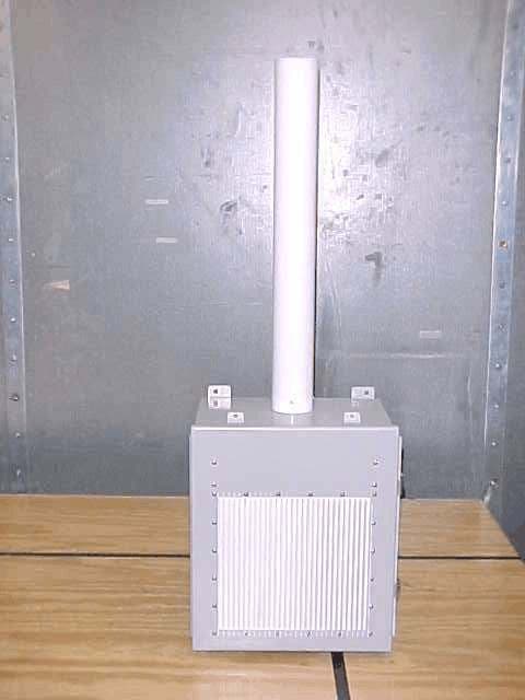
Click to zoom
Application Details
- Equipment Class
- DSS - Part 15 Spread Spectrum Transmitter
- Date of Grant
- Jan 19, 2006
- Application Purpose
- Original Equipment
- Date of Application
- Jan 18, 2006
- Equipment Note
- ConectiSys H-Net Automatic Meter Reader
- Frequency Range
- 902.62000000 - 927.77000000
- Company
- ConectiSys Corporation
- Country
- United States
Documents & Files
Document Text
Text extracted from the exhibit documents filed with the FCC. Open a document above to read the original.
Users Manual
Page 1 of 7 ConectiSys H-Net? 5.0 8Ch Basestation Installation and Operations Manual Sections: I. FCC Warning, Compliance and Radio Frequency Exposure Statements II. Introduction and Basestation Description III. Basestation Mounting and Wiring. IV. Basestation Software Configuration. V. Reference Figures. I. FCC Warning, Compliance and Radio Frequency Exposure Statements FCC Warning The users manual or instruction manual for an intentional or unintentional radiator shall caution the user that changes or modifications not expressly approved by the party responsible for compliance (ConectiSys) could void the user's authority to operate the equipment. FCC Compliance Statement This device complies with Part 15 of the FCC Rules. Operation is subjected to the following two conditions 1) this device may not cause harmful interference and 2) this device must accept any interference received, including interference that may cause undesired operation. FCC Radio Frequency Exposure Statement The H-Net? 5.0 8Ch Base Station has been evaluated under FCC Bulletin OET 65 and found compliant to the requirements as set forth in CFR 47 Sections 2.1091, 2.1093, and 15.247 (b) (4) addressing RF Exposure from radio frequency devices. The radiated output power of the H-Net? 5.0 8Ch Base Station is well below the FCC radio frequency exposure limits. Nevertheless, this device should be installed in such a manner that the potential for human contact during normal operation is minimized. To ensure RF exposure compliance, in order to comply with RF exposure limits established in the ANSI C95.1 standards, the distance between the antenna and the user should not be less than 20 cm. Page 2 of 7 II. Introduction and Basestation Description Introduction: The H-Net? radio system has been developed by ConectiSys Corp. as an Automatic Meter Reading (AMR) solution for residential and commercial energy markets. H-Net? utilizes a proprietary protocol for two-way communication using a wireless, tower-less network. The H-Net? 5.0 Eight Channel Basestation is a controlling hub for an H-Net? 5.0 radio system network. The basestation provides a central point for data collection from individual meter units, synchronizing and communicating with individual meters in a TDMA scheme. The eight channel basestation is designed to receive data from up to eight meter units simultaneously time in the basestation’s receive sequence. The design provides a solid foundation for future iterations of basestations that will integrate additional receivers. The basestation consists of a PC/104 computer, Compact Flash drive, AC/DC converter, DC/DC converter, battery back-up system, surge protectors and 8 H-Net? 5.0 radios (one of which has been modified to be the transmitter unit, while the other seven will only receive). The power system is comprised of a 120VAC to 12VDC converter with a 12VDC-battery backup and a 12VDC to 5VDC/3.3VDC converter to power the PC/104 and radios respectively. The radio system is composed of eight radios, each composed of two PCB assemblies (controller module and RF module), a multiplexing board and an omnidirectional vertically mounted, horizontally polarized antenna. The controller and RF modules interface together via PCB mounted headers. The controllers are interfaced to the PC/104 via RS232 serial lines. The antenna is weather sealed and mounted on the top of the basestation. The basestation is housed within an environmentally sealed enclosure meeting the following standards: UL 508 Type 3R, 4, 12 and 13 CSA Type 3R, 4, 12 and 13 Complies with ??NEMA Type 3R, 4, 12 and 13 ??JIC EGP-1-1967 unless marked¹ ??IEC 529, IP66 Page 3 of 7 III. Installation and wiring: WARNING: Failure to wire as instructed may cause damage to device or connected equipment or personal injury. To be installed or checked by an electrician or qualified person only. Note: ??Before basestation installation has begun, the basestation should checked to ensure the AC circuit breaker and battery backup switches are in the off position. (See Figures 1 and 5). ??All wiring devices must be installed and used in accordance with applicable listings, ratings, and codes. References to National Electrical Code are applicable to installations in the United States only. 1. Basestation Mounting: a. The H-Net? Eight-channel basestation comes configured to be mounted on a vertical 2 ¾ inch diameter pole. b. Mounting pole must be sturdy enough to support 50 pounds against maximum local wind conditions. c. Basestation mounting height will be determined by a qualified technician after a local site survey has been conducted. d. Basestation is mounted to pole by two 360° Clamping U-Bolts. (See Figure 2). 2. Basestation Wiring a. 120VAC and modem wiring are to be run through ½ inch flexible metallic conduit designed for such applications. b. Conduit is connected to bottom of basestation through two Liqua- Seal connectors. (See Figure 3). c. Modem cable should be run through left conduit and 120VAC through the right. d. Modem cable should be a standard RJ-11 telephone cord connected to a direct telephone line. e. Modem cable is plugged into topside of telephone line surge protector (See Figure 4). f. 120VAC wiring is connected circuit breaker and ground block. Wiring should be white wire (neutral) connected to circuit breaker left terminal, black wire (hot) connected to circuit breaker right terminal and green wire (ground) connected to the green and yellow DIN rail grounding block (See Figure 4). Page 4 of 7 IV. Software Configuration: H-Net? 5.0 Eight Channel Basestation software needs to be configured for each installation. 1. After the basestation has been properly installed connect a PS/2 mouse and keyboard to the indicated connectors in the basestation. 2. Connect a standard VGA PC monitor to the DB15 monitor connector. (See Figure 5). 3. Power up monitor. 4. Power up basestation by flipping the battery back up and circuit breaker switches to the on position. 5. Af…
Text truncated - open the document above for the full version.
Cover Letter(s)
24307 Magic Mountain Parkway, Suite 41, Valencia, Ca. 91355/Off 661 295 6763/Fax 661 295 5981 11 November 2004 American Telecommunications Certification Body, Inc. 6731 Whittier Avenue Suite C110 McLean, VA 22101 To Whom It May Concern: Please be advised that ConectiSys Corporation authorizes DNB Engineering, Inc. to act on our behalf, until otherwise notified, for applications submitted to the Federal Communications Commission and/or American Telecommunications Certification Body, Inc.. We certify that we are not subject to denial of federal benefits, which includes FCC benefits, pursuant to Section 5301 of the Anti-Drug Abuse Act of 1988, U.S.C. 862. Further, no party to the application, as defined in 47 CFR 1.2002(b), is subject to denial of federal benefits, that includes FCC benefits. DNB Contact Info: Les Payne Sr Engineering Manager 5969 Robinson Ave Riverside, CA 92503 [email protected] Tel 951-637-2630 Fax 951-637-2704 www.dnbenginc.com Thank you for your attention to this matter. Sincerely, Thanks Marsha Casspi Marsha Casspi Marketing Director ConectiSys Corporation 24037 Magic Mountain Parkway Valencia, CA 91355 (661) 295-6763 x201 (Phone) (661) 295-5981 (Fax) ConectiSys C O R P O R A T I O N
Cover Letter(s)
American Telecommunications Certification Body Inc. 6731 Whittier Ave, McLean, VA 22101 December 22, 2005 RE: FCC ID: SNKHNET50BS8_ATCB003040 Attention: Les Payne I have a few comments on this Application. Please note that further comments may arise in response to answers provided to the questions below. 1. Please note that you have provided a photo of the radio rf board with the shields removed, but there is no photo provided of the multiplexing board which also has shields. Please provide photos of boards with shields removed (only one rf transmitter need be shown). 2. Please note that the schematics for the transmitter board states, “09-14-04 Added a circuit board to hold J3, J4, L6 and C32 for the 8 channel Base Station application. MAH”. The internal photos however appear to be only of the receiver version and not of the transmitter. Please provide a photo of this circuit board and how it connects to the modified transmitter board. 3. Please explain how the modification provides connections to J3 and J4 on the transmitter board as related to the connections from the other receiver boards. The explanation does not appear to agree with the schematics. For example, the terms RF, ANT; RF, Out; and RF, in are shown from the modified TX unit in the “8C Base Schematic”, while only the term RF is applied to the other boards. The multiplexer uses the terms RF, J1 etc. Are the terms RF from the receiver boards the same as the term ‘RF, in’ from the modified transmitter? Also, J2 is referenced as controlling TXD, RXD and GND pins on all of the spread spectrum boards. However, J2 as shown on the tx and rx schematics appears to be an antenna connector and not as indicated in the 8C base schematic (i.e. TXD, RXD, GND). Please provide an operational description that clearly explains how this works and how the other radios boards prevented from transmitting and which clearly identifies that correct jacks etc. 4. FYI – please note that units of measurement should always be applied to readings. Please note that it is assumed that the meter reading, ant factor, cable factor and am factor are in dB. In the future, please identify the units of measurements for all data columns. 5. Please note that the 731 states that the operating frequency range of the device is from 902.62 to 927.77MHz. Please note however, that the list of frequencies in the hopping sequence chart shows that for pattern 1 the frequency range is 902.8MHz to 927.6MHz and that the frequency range for pattern 8 is 903.15MHz to 927.95MHz. This means that the total frequency range for the device is from 902.8MHz to 927.95MHz. Please correct the lowest frequency range listed on the 731 to coincide with the lowest frequency listed in the hopping table (902.8MHz) and please provide data that shows compliance for the total frequency range. Alternately, please show how this device only uses pattern 1 through pattern 3 as any other pattern would exceed the highest frequency listed on the 731 and tested in the report. Alternately, please test a transmitter operating under pattern 8 to show compliance with the highest frequency listed in the hopping table. Dennis Ward mailto:[email protected] The items indicated above must be submitted before processing can continue on the above referenced application. Failure to provide the requested information may result in application termination. Correspondence should be considered part of the permanent submission and may be viewed from the Internet after a Grant of Equipment Authorization is issued. Please do not respond to this correspondence using the email reply button. In order for your response to be processed expeditiously, you must submit your documents through the AmericanTCB.com website. Also, please note that partial responses increase processing time and should not be submitted. z Page 2 December 22, 2005 Any questions about the content of this correspondence should be directed to the sender.
Cover Letter(s)
Frequency # Pattern 1 Pattern 2 Pattern 3 Pattern 4 Pattern 5 Pattern 6 Pattern 7 Pattern 8 16908.62908.67908.72908.77908.82908.87908.92908.97 37917.02917.07917.12917.17917.22917.27917.32917.37 21910.62910.67910.72910.77910.82910.87910.92910.97 3903.42903.47903.52903.57903.62903.67903.72903.77 5904.22904.27904.32904.37904.42904.47904.52904.57 1902.62902.67902.72902.77902.82902.87902.92902.97 8905.42905.47905.52905.57905.62905.67905.72905.77 49921.82921.87921.92921.97922.02922.07922.12922.17 31914.62914.67914.72914.77914.82914.87914.92914.97 59925.82925.87925.92925.97926.02926.07926.12926.17 26912.62912.67912.72912.77912.82912.87912.92912.97 54923.82923.87923.92923.97924.02924.07924.12924.17 15908.22908.27908.32908.37908.42908.47908.52908.57 40918.22918.27918.32918.37918.42918.47918.52918.57 62927.02927.07927.12927.17927.22927.27927.32927.37 24911.82911.87911.92911.97912.02912.07912.12912.17 4903.82903.87903.92903.97904.02904.07904.12904.17 42919.02919.07919.12919.17919.22919.27919.32919.37 2903.02903.07903.12903.17903.22903.27903.32903.37 9905.82905.87905.92905.97906.02906.07906.12906.17 56924.62924.67924.72924.77924.82924.87924.92924.97 11906.62906.67906.72906.77906.82906.87906.92906.97 14907.82907.87907.92907.97908.02908.07908.12908.17 38917.42917.47917.52917.57917.62917.67917.72917.77 60926.22926.27926.32926.37926.42926.47926.52926.57 47921.02921.07921.12921.17921.22921.27921.32921.37 39917.82917.87917.92917.97918.02918.07918.12918.17 48921.42921.47921.52921.57921.62921.67921.72921.77 63927.42927.47927.52927.57927.62927.67927.72927.77 17909.02909.07909.12909.17909.22909.27909.32909.37 50922.22922.27922.32922.37922.42922.47922.52922.57 29913.82913.87913.92913.97914.02914.07914.12914.17 43919.42919.47919.52919.57919.62919.67919.72919.77 19909.82909.87909.92909.97910.02910.07910.12910.17 33915.42915.47915.52915.57915.62915.67915.72915.77 41918.62918.67918.72918.77918.82918.87918.92918.97 22911.02911.07911.12911.17911.22911.27911.32911.37 6904.62904.67904.72904.77904.82904.87904.92904.97 61926.62926.67926.72926.77926.82926.87926.92926.97 57925.02925.07925.12925.17925.22925.27925.32925.37 27913.02913.07913.12913.17913.22913.27913.32913.37 20910.22910.27910.32910.37910.42910.47910.52910.57 51922.62922.67922.72922.77922.82922.87922.92922.97 36916.62916.67916.72916.77916.82916.87916.92916.97 34915.82915.87915.92915.97916.02916.07916.12916.17 52923.02923.07923.12923.17923.22923.27923.32923.37 25912.22912.27912.32912.37912.42912.47912.52912.57 23911.42911.47911.52911.57911.62911.67911.72911.77 10906.22906.27906.32906.37906.42906.47906.52906.57 Frequency in MHz 7905.02905.07905.12905.17905.22905.27905.32905.37 12907.02907.07907.12907.17907.22907.27907.32907.37 46920.62920.67920.72920.77920.82920.87920.92920.97 58925.42925.47925.52925.57925.62925.67925.72925.77 45920.22920.27920.32920.37920.42920.47920.52920.57 18909.42909.47909.52909.57909.62909.67909.72909.77 55924.22924.27924.32924.37924.42924.47924.52924.57 13907.42907.47907.52907.57907.62907.67907.72907.77 30914.22914.27914.32914.37914.42914.47914.52914.57 53923.42923.47923.52923.57923.62923.67923.72923.77 32915.02915.07915.12915.17915.22915.27915.32915.37 28913.42913.47913.52913.57913.62913.67913.72913.77 44919.82919.87919.92919.97920.02920.07920.12920.17 35916.22916.27916.32916.37916.42916.47916.52916.57
Cover Letter(s)
Engineering, Inc. 5969 Robinson Avenue Riverside, CA 92503-8620 www.dnbenginc.com attn: Reviewing Engineer Federal Communications Commission 7435 Oakland Mills Road Columbia, MD 21046 RE: CONFIDENTIALITY REQUEST FOR FCC ID: SNKHNET50BS8 To Whom It May Concern: This letter serves as an official request for confidentiality under FCC Rule Section 0.459. We have requested that the schematics and block diagrams required to be submitted with this application be withheld from public review. The items are ConectiSys proprietary information for the product that should not be open to the public or competitors. Please contact me if there is any information you may need. Sincerely, C L Payne III (Agent for ConectiSys Corp) DNB Engineering Inc 5869 Robinson Avenue Riverside, CA 92503 (951) 637-2630 (951) 637-2704 (Fax) [email protected] www.dnbenginc.com
External Photos
Page 83 of 87 Photo 14 External Front Page 84 of 87 Photo 15 External Rear Page 85 of 87 Photo 16 External Angle
ID Label/Location Info
Page 5 of 87 2.1033 (b) (2)FCC Identifier FCC ID: SNKHNET50BS8 ConectiSys Corp. Model: H-NET™ 5.0-BS8 FCC ID: SNKHNET50BS8 S/N: 000000 This device complies with part 15 of the FCC Rules. Operation is subject to the following two conditions: (1) This device may not cause harmful interference, and (2) this device must accept any interference received, including interference that may cause undesired operation. Figure 1 - Label
Internal Photos
Page 70 of 87 Photo 1 Internal RF Transmitter - Component Side Page 71 of 87 Photo 2 Internal RF Transmitter - Solder Side Page 72 of 87 Photo 3 Internal RF Transmitter - with shield mounted - view one Page 73 of 87 Photo 4 Internal RF Transmitter - with shield mounted - view two Page 74 of 87 Photo 5 Internal Controller board - component side Page 75 of 87 Photo 6 Internal Controller board - circuit side Page 76 of 87 Photo 7 Internal Label Placement - Inside door Page 77 of 87 Photo 8 Internal Label Close Up Page 78 of 87 Photo 9 Internal Unit with door open Page 79 of 87 Photo 10 Internal Side 1 Page 80 of 87 Photo 11 Internal Side 2 Page 81 of 87 Photo 12Internal Side 3 Page 82 of 87 Photo 13Internal Side 4
Operational Description
Page 13 of 87 2.1033 (b) (4)Brief Description of Circuit Function Introduction: The H-Net radio system has been developed by ConectiSys Corp. TM as an Automatic Meter Reading (AMR) solution for residential and commercial energy markets. H-Net utilizes a proprietary protocol for two-way TM communication using a wireless, tower-less network. The H-Net 5.0 Eight TM Channel Basestation is a controlling hub for an H-Net 5.0 radio system TM network. The basestation provides a central point for data collection from individual meter units, synchronizing and communicating with individual meters in a TDMA scheme. The eight channel basestation is designed to receive data from up to eight meter units simultaneously time in the basestation's receive sequence. The design provides a solid foundation for future iterations of basestations that will integrate additional receivers. The basestation consists of a PC/104 computer, Compact Flash drive, AC/DC converter, DC/DC converter, battery back-up system, surge protectors and 8 H- Net 5.0 radios (one of which has been modified to be the transmitter unit, while TM the other seven will only receive). The power system is comprised of a 120VAC to 12VDC converter with a 12VDC-battery backup and a 12VDC to 5VDC/3.3VDC converter to power the PC/104 and radios respectively. The radio system is composed of eight radios, each composed of two PCB assemblies (controller module and RF module), a multiplexing board and an omnidirectional vertically mounted, horizontally polarized antenna. The controller and RF modules interface together via PCB mounted headers. The controllers are interfaced to the PC/104 via RS232 serial lines. The antenna is weather sealed and mounted on the top of the basestation. The basestation is housed within an environmentally sealed enclosure meeting the following standards: UL 508 Type 3R, 4, 12 and 13 CSA Type 3R, 4, 12 and 13 Complies with NEMA Type 3R, 4, 12 and 13 JIC EGP-1-1967 unless marked' IEC 529, IP66
RF Exposure Info
Page 86 of 87 15.247 (2,b,5) RF Exposure Requirements Reference CFR 47 Part 1.1307(b)(1) RF Exposure – MPE Calculations (902 - 928 MHz Band) Transmitter Power: 332 mW Antenna Gain:6 dB Cable loss:1 dB Frequency range:902 - 928 MHz Assumptions 1. A single ¼ wavelength radiating antenna is assumed. 2. Closest exposure distance is assumed to be 20 cm Calculations The following results shall be assumed to be accurate for the far-field only. These predictions will over-estimate power density in the near–field. Based on the use of a ¼ wavelength radiator, a distance of 20 cm is considered to be in the far-field for all cases. S = PG/4*PI*R 2 P is 332 mW G is 5 dB (Antenna gain – loss) R is 20 cm S = 0.209 mW/cm 2 For Occupational/Controlled Exposure From 300 to 1500 MHz, power density limit is f/1500 mW/cm 2 @ 902 MHz, power density limit is 3.007 mW/cm 2 For General Population/Uncontrolled Exposure From 300 to 1500 MHz, power density limit is f/1500 mW/cm 2 @ 902 MHz, Power density limit is 0.601 mW/cm 2 Conclusion:Meets MPE limits
Test Report
Page 15 of 87 2.1033 (b) (6)Report of Measurements Page 16 of 87 15.207Conducted Emissions (General Provisions) Test Procedure: To measure conducted emissions, the EUT was set upon a wooden table in the shielded enclosure. AC power was fed into the EUT from the Artificial Mains Network. With the Artificial Mains Network connected to an HP 8568B Spectrum Analyzer, and using the HP 9825 Computer/Controller and the HP 85864B EMI Measurement Software, the spectrum was searched from 0.15 - 30 MHz for emissions emanating from the EUT. Frequency of emission (MHz) Conducted Limit (dBuV) Quasi-PeakAverage 0.15 - 0.566 to 56*56 to 46* 0.5 - 55646 5 - 306050 * Decreases with the logarithm of the frequency. EUT operating conditions: The software provided by the client to enable the EUT to transmit continuously. Test Set Up: Page 17 of 87 5969 Robinson Avenue Riverside, CA 92503 (951) 637-2630 FAX (951) 637-2704 Conducted Emissions DNB Job Number:68012Date:31 Aug 2005Specification [X] 15.207 Customer:ConectiSys Corp. Model Number:HNET 5.0-BS8Serial Number:Proto Description:RF Transmitter Set Up Page 18 of 87 5969 Robinson Avenue Riverside, CA 92503 (951) 637-2630 FAX (951) 637-2704 Conducted Emissions DNB Job Number:68012Date:31 Aug 2005Specification [X] 15.207 Customer:ConectiSys Corp. Model Number:HNET 5.0-BS8Serial Number:Proto Description:RF Transmitter Line - Peak Page 19 of 87 5969 Robinson Avenue Riverside, CA 92503 (951) 637-2630 FAX (951) 637-2704 Conducted Emissions DNB Job Number:68012Date:31 Aug 2005Specification [X] 15.207 Customer:ConectiSys Corp. Model Number:HNET 5.0-BS8Serial Number:Proto Description:Wireless Power Usage Monitoring System Neutral - Peak Page 20 of 87 15.209Radiated Emissions (General Provisions) Test Procedure: The EUT was measured on an open area test site (OATS). A measuring distance of at least 3 m shall be used for measurements at frequencies up to 1 GHz. For frequencies above 1 GHz, any suitable measuring distance may be used. The equipment size (excluding the antenna) shall be less than 20 % of the measuring distance. Sufficient precautions shall be taken to ensure that reflections from extraneous objects adjacent to the site do not degrade the measurement results, in particular: - no extraneous conducting objects having any dimension in excess of a quarter wavelength of the highest frequency tested shall be in the immediate vicinity of the site; - all cables shall be as short as possible; as much of the cables as possible shall be on the ground plane or preferably below; and the low impedance cables shall be screened. The EUT shall be placed upon a non-conductive table 1.5 meters above the ground plane and shall be placed in the “worst case” transmitting mode. The EUT shall be rotated 360 degrees to find the azimuth maxima. The receive antenna shall then be raised and lowered between 1 to 4 meters to find the maximum signal emanating from the EUT. This signal strength is then recorded on the data sheets. Frequency (MHz) Field Strength (uV/m) Field Strength (dBuV/m) Measurement Distance (meters) .0009 - 0.4902400/F(kHz) 10 20*(Log(2400/F(kHz)) 300 0.490 - 1.70524000/F(kHz) 10 20*(Log(24000/F(kHz)) 30 1.705 - 30.03029.530 30 - 8810040.03 88 - 21615043.53 216 - 96020046.03 Above 96050054.03 Page 21 of 87 5969 Robinson Avenue Riverside, CA 92503 (951) 637-2630 FAX (951) 637-2704 Radiated Emissions (Spurious) DNB Job Number:68012Date:21 Oct 2005Specification [X] 15.209 Customer:ConectiSys Corp. Model Number:HNET 5.0-BS8Serial Number:Proto Description:Wireless Power Usage Monitoring System Test Set Up Page 22 of 87 5969 Robinson Avenue Riverside, CA 92503 (951) 637-2630 FAX (951) 637-2704 Radiated Emissions (Spurious) DNB Job Number:68012Date:21 Oct 2005Specification [X] 15.209 Customer:ConectiSys Corp. Model Number:HNET 5.0-BS8Serial Number:Proto Description:Wireless Power Usage Monitoring System Test Set Up - Bicon Antenna Page 23 of 87 5969 Robinson Avenue Riverside, CA 92503 (951) 637-2630 FAX (951) 637-2704 Radiated Emissions (Spurious) DNB Job Number:68012Date:21 Oct 2005Specification [X] 15.209 Customer:ConectiSys Corp. Model Number:HNET 5.0-BS8Serial Number:Proto Description:Wireless Power Usage Monitoring System Test Set Up - Log Periodic Page 24 of 87 5969 Robinson Avenue Riverside, CA 92503 (951) 637-2630 FAX (951) 637-2704 Radiated Emissions (Spurious) DNB Job Number:68012Date:21 Oct 2005Specification [X] 15.209 Customer:ConectiSys Corp. Model Number:HNET 5.0-BS8Serial Number:Proto Description:Wireless Power Usage Monitoring System Test Set Up - DRG Horn Page 25 of 87 5969 Robinson Avenue Riverside, CA 92503 (951) 637-2630 FAX (951) 637-2704 Radiated Emissions (General) DNB Job Number:68012Date:21 Oct 2005Specification [X] 15.209 Customer:ConectiSys Corp. Model Number:HNET 5.0-BS8Serial Number:Proto Description:Wireless Power Usage Monitoring System Correction Factors EUT is in conformance with FCC 15.209XYESNOSignedTom Elders FreqMeter in dBuV/min uV/mPositions BcnLogCblAmpCorrLimitDeltaCorrLimDeltaTableTypPolHgt 143.98646.011.601.7-24.235.143.5-8.457150-93271PKH2.65 225.02443.3012.42.2-24.233.746.0-12.348200-1520PKH1.04 229.07945.7012.42.2-24.236.146.0-9.964200-13692PKH4.00 230.41547.9012.42.2-24.238.346.0-7.782200-11892PKH4.00 233.32554.2012.32.3-24.244.646.0-1.4170200-3082QPH4.00 239.99154.2012.32.3-24.344.546.0-1.5168200-32249QPH3.61 241.61951.5012.32.3-24.341.846.0-4.2123200-77249PKH3.61 249.63249.6012.22.3-24.339.846.0-6.298200-102249PKH3.61 253.97246.9012.32.3-24.337.246.0-8.872200-128249PKH3.61 258.32152.8012.32.4-24.343.246.0-2.8145200-55249PKH3.61 266.65349.3012.52.4-24.439.846.0-6.298200-102272PKH3.61 274.97949.1012.62.4-24.439.746.0-6.397200-103272PKH3.61 282.19743.0013.02.4-24.43446.0-1250200-150272PKH3.61 44.18741.511.100.7-24.32940-1128100-72228PKV1.00 109.68744.510.101.4-24.231.843.5-11.739150-111184PKV1.00 141.11044.811.601.7-24.233.943.5-9.650150-100255PKV1.00 143.98747.211.601.7-24.236.343.5-7.265150-85106QPV1.00 225.79343.6012.42.2-2…
Text truncated - open the document above for the full version.
Test Setup Photos
Page 17 of 87 5969 Robinson Avenue Riverside, CA 92503 (951) 637-2630 FAX (951) 637-2704 Conducted Emissions DNB Job Number:68012Date:31 Aug 2005Specification [X] 15.207 Customer:ConectiSys Corp. Model Number:HNET 5.0-BS8Serial Number:Proto Description:RF Transmitter Set Up Page 22 of 87 5969 Robinson Avenue Riverside, CA 92503 (951) 637-2630 FAX (951) 637-2704 Radiated Emissions (Spurious) DNB Job Number:68012Date:21 Oct 2005Specification [X] 15.209 Customer:ConectiSys Corp. Model Number:HNET 5.0-BS8Serial Number:Proto Description:Wireless Power Usage Monitoring System Test Set Up - Bicon Antenna Page 23 of 87 5969 Robinson Avenue Riverside, CA 92503 (951) 637-2630 FAX (951) 637-2704 Radiated Emissions (Spurious) DNB Job Number:68012Date:21 Oct 2005Specification [X] 15.209 Customer:ConectiSys Corp. Model Number:HNET 5.0-BS8Serial Number:Proto Description:Wireless Power Usage Monitoring System Test Set Up - Log Periodic Page 24 of 87 5969 Robinson Avenue Riverside, CA 92503 (951) 637-2630 FAX (951) 637-2704 Radiated Emissions (Spurious) DNB Job Number:68012Date:21 Oct 2005Specification [X] 15.209 Customer:ConectiSys Corp. Model Number:HNET 5.0-BS8Serial Number:Proto Description:Wireless Power Usage Monitoring System Test Set Up - DRG Horn Page 47 of 87 5969 Robinson Avenue Riverside, CA 92503 (951) 637-2630 FAX (951) 637-2704 Measurement Test Set Up DNB Job Number:68012Date:10 Nov 2005Conformance Standard FCC Part 15 Customer:ConectiSys Corp. Inc Model Number:HNET 5.0-BS8Serial Number:Proto Description:Wireless Power Usage Monitoring SystemClause 15.247 Antenna Conducted Measurement Set Up
Contact Information
Applicant
Marsha Casspi(Marketing Developer)
Technical Contact
DNB Engineering InC.Les Payne
5969 Robinson Avenue · Riverside, California · United States
Test Firm
DNB Engineering, Inc.Mike Neis
Technical Specifications
| # | Rule Parts | Frequency Range | Power Output |
|---|---|---|---|
| 1 | 15C | 902.62 MHz - 927.77 MHz | 332.00 mW |
Other Applications from ConectiSys Corporation
SNKHNET50BS
Mar 06, 2005Wireless Power Usage Monitoring System
Equipment Class
DSS - Part 15 Spread Spectrum Transmitter
SNKHNET50
Nov 21, 2004Wireless Power Usage Monitoring System
Equipment Class
DSS - Part 15 Spread Spectrum Transmitter