SP3-02201000Car Entry System Transceiver
Ericsson Antenna Technology Germany GmbH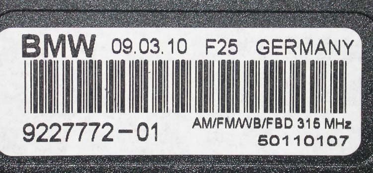
Click to zoom
Application Details
- Equipment Class
- DXX - Part 15 Low Power Communication Device Transmitter
- Date of Grant
- Sep 21, 2010
- Application Purpose
- Original Equipment
- Date of Application
- Sep 21, 2010
- Equipment Note
- Car Entry System Transceiver
- Frequency Range
- 314.60000000 - 315.00000000
- Country
- Germany
Documents & Files
Document Text
Text extracted from the exhibit documents filed with the FCC. Open a document above to read the original.
Users Manual
Federal Communications Commission 7435 Oakland Mills Road Columbia, MD 21046 Re: Compliance Statement in Car Manual / FCC ID: SP3-02201000 Dear Sirs, Our client’s products with the above FCC ID code are low frequency transmitters. The products will be installed in cars before they will be placed into the market. Hereby our client assures that the following caution statement as per CFR 47, Part 15, § 15.21 will be included in the owner’s manual of the cars: The title “CAUTION TO USERS” or “FCC Warning:” “NOTE:” or relevant title and “Changes or modifications not expressly approved by the party responsible for compliance could void the user’s authority to operate the equipment.” In addition our client also assures that the following statement will be included in the manual as per CFR 47, Part 15, § 15.19 (a) (3). This device complies with Part 15 of the FCC Rules. Operation is subject to the following two conditions: (1) this device may not cause harmful interference, and (2) this device must accept any interference received, including interference that may cause undesired operation. Strasskirchen, 31.08.2010 Sincerely, Thomas Ring Manager Certification mikes-testingpartners gmbh Ohmstrasse 2-4 94342 Strasskirchen, Germany Phone: ++49 9424 9481 0 Fax: ++49 9424 9481 240
External Photos
FCC ID: SP3-02201000 mikes-testingpartners gmbh File No. T34252-00-02HS, page 5 of 31 Ohmstrasse 2-4 x 94342 STRASSKIRCHEN x GERMANY Tel.:+49(0)9424-94810 x Fax: +49(0)9424-9481240 Rev. No. 1.1, 05.11.2008 3 EQUIPMENT UNDER TEST 3.1 Photo documentation of the EUT External view: FCC ID: SP3-02201000 mikes-testingpartners gmbh File No. T34252-00-02HS, page 6 of 31 Ohmstrasse 2-4 x 94342 STRASSKIRCHEN x GERMANY Tel.:+49(0)9424-94810 x Fax: +49(0)9424-9481240 Rev. No. 1.1, 05.11.2008
ID Label/Location Info
IC ID Canada FCC ID USA Functions Approval ID of Kathrein Vehicle type Date of manufacture according to BMW GS 91004-C BMW ID No. according to BMW GS 91001 BMW Logo according to BMW GS 91002
Internal Photos
FCC ID: SP3-02201000 mikes-testingpartners gmbh File No. T34252-00-02HS, page 7 of 31 Ohmstrasse 2-4 x 94342 STRASSKIRCHEN x GERMANY Tel.:+49(0)9424-94810 x Fax: +49(0)9424-9481240 Rev. No. 1.1, 05.11.2008 Internal view: FCC ID: SP3-02201000 mikes-testingpartners gmbh File No. T34252-00-02HS, page 8 of 31 Ohmstrasse 2-4 x 94342 STRASSKIRCHEN x GERMANY Tel.:+49(0)9424-94810 x Fax: +49(0)9424-9481240 Rev. No. 1.1, 05.11.2008 FCC ID: SP3-02201000 mikes-testingpartners gmbh File No. T34252-00-02HS, page 9 of 31 Ohmstrasse 2-4 x 94342 STRASSKIRCHEN x GERMANY Tel.:+49(0)9424-94810 x Fax: +49(0)9424-9481240 Rev. No. 1.1, 05.11.2008
Test Report
FCC ID: SP3-02201000 mikes-testingpartners gmbh File No. T34252-00-02HS, page 1 of 31 Ohmstrasse 2-4 x 94342 STRASSKIRCHEN x GERMANY Tel.:+49(0)9424-94810 x Fax: +49(0)9424-9481240 Rev. No. 1.1, 05.11.2008 EMI -- T E S T R E P O R T - FCC Part 15.231 - Test Report No. : T34252-00-02HS 10. September 2010 ______________________________________________________________________________________________ Date of issue Type / Model Name : 02201000 Product Description : FBDII transceiver of keyless entry system Applicant : Kathrein-Werke KG Address : Anton-Kathrein-Str. 1-3 83004 ROSENHEIM, GERMANY Manufacturer : Kathrein-Werke KG Address : Anton-Kathrein-Str. 1-3 83004 ROSENHEIM, GERMANY Licence holder : Kathrein-Werke KG Address : Anton-Kathrein-Str. 1-3 83004 ROSENHEIM, GERMANY Test Result according to the standards listed in clause 1 test standards: POSITIVE The test report merely corresponds to the test sample. It is not permitted to copy extracts of these test results without the written permission of the test laboratory. DAT-P-207/05-00 Registration No. DAT-P-207/05 FCC ID: SP3-02201000 mikes-testingpartners gmbh File No. T34252-00-02HS, page 2 of 31 Ohmstrasse 2-4 x 94342 STRASSKIRCHEN x GERMANY Tel.:+49(0)9424-94810 x Fax: +49(0)9424-9481240 Rev. No. 1.1, 05.11.2008 Contents 1 TEST STANDARDS 3 2 SUMMARY 4 3 EQUIPMENT UNDER TEST 5 3.1 Photo documentation of the EUT 5 3.2 Power supply system utilised 10 3.3 Short description of the equipment under test (EUT) 10 4 TEST ENVIRONMENT 11 4.1 Address of the test laboratory 11 4.2 Environmental conditions 11 4.3 Statement of the measurement uncertainty 11 4.4 Measurement protocol for FCC 11 4.5 Determination of worst case measurement conditions 13 5 TEST CONDITIONS AND RESULTS 14 5.1 Conducted emissions 14 5.2 Field strength of the fundamental wave 14 5.3 Spurious emissions (magnetic field) 9 kHz – 30 MHz 16 5.4 Spurious emissions radiated (electric field) 18 5.5 Correction for pulse operation (duty cycle) 21 5.6 Emission bandwidth 25 5.7 Signal deactivation 28 6 USED TEST EQUIPMENT AND ACCESSORIES 31 FCC ID: SP3-02201000 mikes-testingpartners gmbh File No. T34252-00-02HS, page 3 of 31 Ohmstrasse 2-4 x 94342 STRASSKIRCHEN x GERMANY Tel.:+49(0)9424-94810 x Fax: +49(0)9424-9481240 Rev. No. 1.1, 05.11.2008 1 TEST STANDARDS The tests were performed according to following standards: FCC Rules and Regulations Part 15, Subpart A - General (October, 2009) Part 15, Subpart A, Section 15.31 Measurement standards Part 15, Subpart A, Section 15.33 Frequency range of radiated measurements Part 15, Subpart A, Section 15.35 Measurement detector functions and bandwidths FCC Rules and Regulations Part 15, Subpart C - Intentional Radiators (October, 2009) Part 15, Subpart C, Section 15.203 Antenna requirement Part 15, Subpart C, Section 15.204 External radio frequency power amplifiers and antenna modifications Part 15, Subpart C, Section 15.205 Restricted bands of operation Part 15, Subpart C, Section 15.207 Conducted limits Part 15, Subpart C, Section 15.209 Radiated emission limits, general requirements Part 15, Subpart C, Section 15.231 Periodic operation in the band 40.66-40.70 MHz and above 70 MHz ANSI C63.4: 2003 Methods of Measurement of Radio-Noise Emissions from Low- Voltage Electrical and Electronic Equipment in the Range of 9 kHz to 40 GHz. CISPR 16-4-2: 2003 Uncertainty in EMC measurement CISPR 22: 2005 Information technology equipment EN 55022: 2006 FCC ID: SP3-02201000 mikes-testingpartners gmbh File No. T34252-00-02HS, page 4 of 31 Ohmstrasse 2-4 x 94342 STRASSKIRCHEN x GERMANY Tel.:+49(0)9424-94810 x Fax: +49(0)9424-9481240 Rev. No. 1.1, 05.11.2008 2 SUMMARY GENERAL REMARKS: The EUT is a device with dedicated antenna. The antenna is realised as a special structure in the rear window defroster of a car. For the firmware output power setting please see point 4.5 determination of worst case. The measurements with antenna were performed using an original installed window antenna in a trunk of a car in order to get real circumstances for radiating. Operation modes: TX modes, the EUT can be set into special operation modes for measurement purposes are not available in the application. As TX mode can be set TX continuous modulated and unmodulated. RX mode, the EUT cannot be switched off; therefore the RX mode is similar as the standby mode. The lowest power consumption is reached, nearly all activities are stopped. If the key ID is received, the EUT wake up and works as intended. The EUT may have the following options: AM/FM-DIVERSITY/WB/FBDII 315 F25 This test report is based on the model with all options. FINAL ASSESSMENT: The equipment under test fulfills the EMI requirements cited in clause 1 test standards. Date of receipt of test sample : acc. to storage records Testing commenced on : 20 August 2010 Testing concluded on : 23 August 2010 Checked by: Tested by: Klaus Gegenfurtner Dipl.-Ing.(FH) Manager: Radio Group Hermann Smetana Dipl.-Ing.(FH) Radio Expert FCC ID: SP3-02201000 mikes-testingpartners gmbh File No. T34252-00-02HS, page 5 of 31 Ohmstrasse 2-4 x 94342 STRASSKIRCHEN x GERMANY Tel.:+49(0)9424-94810 x Fax: +49(0)9424-9481240 Rev. No. 1.1, 05.11.2008 3 EQUIPMENT UNDER TEST 3.1 Photo documentation of the EUT External view: FCC ID: SP3-02201000 mikes-testingpartners gmbh File No. T34252-00-02HS, page 6 of 31 Ohmstrasse 2-4 x 94342 STRASSKIRCHEN x GERMANY Tel.:+49(0)9424-94810 x Fax: +49(0)9424-9481240 Rev. No. 1.1, 05.11.2008 FCC ID: SP3-02201000 mikes-testingpartners gmbh File No. T34252-00-02HS, page 7 of 31 Ohmstrasse 2-4 x 94342 STRASSKIRCHEN x GERMANY Tel.:+49(0)9424-94810 x Fax: +49(0)9424-9481240 Rev. No. 1.1, 05.11.2008 Internal view: FCC ID: SP3-02201000 mikes-testingpartners gmbh File No. T34252-00-02HS, page 8 of 31 Ohmstrasse 2-4 x 94342 STRASSKIRCHEN x GERMANY Tel.:+49(0)9424-94810 x Fax: +49(0)9424-9481240 Rev. No. 1.1, 05.11.2008 FCC ID: SP3-02201000 mikes-testingpartners gmbh File No. T34252-00-02HS, page 9 of 31 Ohmstrasse 2-4 …
Text truncated - open the document above for the full version.
Test Setup Photos
FCC ID: SP3-02201000 mikes-testingpartners gmbh File No. T34252-00-02HS, page 15 of 31 Ohmstrasse 2-4 x 94342 STRASSKIRCHEN x GERMANY Tel.:+49(0)9424-94810 x Fax: +49(0)9424-9481240 Rev. No. 1.1, 05.11.2008 Position of the EUT: 5.2.1 Applicable standard According to FCC Part 15C, Section 15.231(b): The field strength of emissions from intentional radiators shall not exceed the effective field strength limits. 5.2.2 Description of Measurement The radiated power of the fundamental wave from the EUT is measured as described under item 4.4.3. The set up of the EUT is in accordance to ANSI C63.4. The measurement has been performed in unmodulated TX mode at normal conditions. 5.2.3 Test result Frequency (MHz) Level Pk (dBμV) Duty cycle corr. (dB) Correct. factor (dB/m) Corrected level dB(μV/m) Limit dB(μV/m) Delta (dB) 314.6 73.8 -17.0 17.3 74.1 75.6 -1.5 315.0 73.7 -17.0 17.3 74.0 75.6 -1.6 Limit according to FCC Section 15.231(b): *Linear interpolation The requirements are FULFILLED. Remarks: Field strength of fundamental @ 3m Effective limit for 315 MHz Frequency (MHz) (μV/m) dB(μV/m) (μV/m) dB(μV/m) 260 - 470 3750 to 12500 )* 71.4 to 81.9 )* 6042 75.6 FCC ID: SP3-02201000 mikes-testingpartners gmbh File No. T34252-00-02HS, page 16 of 31 Ohmstrasse 2-4 x 94342 STRASSKIRCHEN x GERMANY Tel.:+49(0)9424-94810 x Fax: +49(0)9424-9481240 Rev. No. 1.1, 05.11.2008 5.3 Spurious emissions (magnetic field) 9 kHz – 30 MHz For test instruments and accessories used see section 6 Part SER 1. 5.3.1 Description of the test location Test location: OATS1 Test distance: 3 metres 5.3.2 Photo documentation of the test set-up 5.3.3 Applicable standard According to FCC Part 15C, Section 15.209: The emissions from intentional radiators shall not exceed the effective field strength limits. 5.3.4 Description of Measurement The magnetic field strength from the EUT will be measured in an open area test site in the frequency range of 9 kHz to 30 MHz using a tuned receiver and a shielded loop antenna. The set up of the Equipment under test will be in accordance to ANSI C63.4. In the case where larger measuring distances are required the results will extrapolated based on the values measured on the closer distances according to Section 15.31(f)(2)(2). The final measurement will be performed with an EMI Receiver set to Quasi Peak detector except for the frequency bands 9 kHz to 90 kHz and 110 to 490 kHz where an average detector will be used according to Section 15.209(d)(2). Instrument setting: 9 kHz – 150 kHz: RBW: 200 Hz 150 kHz – 30 MHz: RBW: 9 kHz FCC ID: SP3-02201000 mikes-testingpartners gmbh File No. T34252-00-02HS, page 18 of 31 Ohmstrasse 2-4 x 94342 STRASSKIRCHEN x GERMANY Tel.:+49(0)9424-94810 x Fax: +49(0)9424-9481240 Rev. No. 1.1, 05.11.2008 5.4 Spurious emissions radiated (electric field) For test instruments and accessories used see section 6 Part SER 2, SER 3. 5.4.1 Description of the test location Test location: OATS1 Test location: Anechoic Chamber A2 Test distance: 3 metres 5.4.2 Photo documentation of the test set-up FCC ID: SP3-02201000 mikes-testingpartners gmbh File No. T34252-00-02HS, page 21 of 31 Ohmstrasse 2-4 x 94342 STRASSKIRCHEN x GERMANY Tel.:+49(0)9424-94810 x Fax: +49(0)9424-9481240 Rev. No. 1.1, 05.11.2008 5.5 Correction for pulse operation (duty cycle) For test instruments and accessories used see section 6 Part DC. 5.5.1 Description of the test location Test location: AREA4 5.5.2 Photo documentation of the test set-up 5.5.3 Applicable standard According to FCC Part 15C, Section 15.35(c): The emissions from intentional radiators shall not exceed the effective field strength limits. 5.5.4 Description of Measurement The duty cycle measurement is performed using an arbitrary waveform generator and an RF-Generator as stimulus for the receiver. The spectrum analyser displays the puls train in cero span mode. The EUT is only able to send the right puls train in normal mode. The stimulus shall provide with the shortest reaction possible for this programmed puls train. The puls train have two main pulses, a “button pressed acknowledge puls” and a “button released acknowledge puls”. The puls train is programmed for CH1 and CH2 as “button pressed puls” (9 ms) + min blank time (45 ms) + “button released telegram” (37 ms) + blank time (4 ms) + “button released acknowledge puls” (9 ms). The puls train is recorded. Other usable remote controller show the same behaviour as below described, the difference between the remote controllers is the Byte “Mode only”.
Contact Information
Applicant
Mikael Hofverberg(Head of R&D KMC)
Test Firm
CSA Group Bayern GmbHThomas Weise
Technical Specifications
| # | Rule Parts | Frequency Range | Power Output |
|---|---|---|---|
| 1 | 15C | 314.6 MHz - 315 MHz | - |
Other Applications from Ericsson Antenna Technology Germany GmbH
SP3-86010148V01
Sep 05, 2013Positioning tool for antennas
Equipment Class
DXX - Part 15 Low Power Communication Device Transmitter
SP3-86010153
Sep 02, 2013Positioning tool for antennas
Equipment Class
DXX - Part 15 Low Power Communication Device Transmitter
SP3-86010156
Nov 12, 2012Antenna Line Configurator
Equipment Class
DTS - Digital Transmission System