SQTMR400VHF Radio Modem
Racom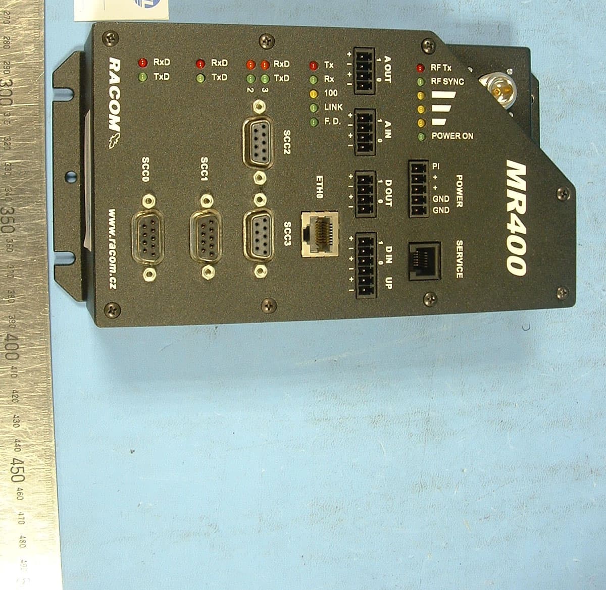
Click to zoom
Application Details
- Equipment Class
- TNB - Licensed Non-Broadcast Station Transmitter
- Date of Grant
- Jan 31, 2005
- Application Purpose
- Original Equipment
- Date of Application
- Jan 31, 2005
- Equipment Note
- VHF Radio Modem
- Frequency Range
- 421.00000000 - 512.00000000
- Company
- Racom
- Country
- Czech Republic
Documents & Files
Document Text
Text extracted from the exhibit documents filed with the FCC. Open a document above to read the original.
Users Manual
Table of Contents Introduction .................................................................................................................................................. 3 1. Radio Modem MR400 ............................................................................................................................. 4 Radio Part MR400 ......................................................................................................................................... 5 Modem Part ............................................................................................................................................ 5 3. MR 400 Connectors ...................................................................................................................................... 6 Antenna .................................................................................................................................................... 6 Serial Interface ....................................................................................................................................... 6 RS232, RS422 and RS485 Connectors..................................................................................... 6 Distinguishing Data Modules by Colour .......................................................................................... 6 Ethernet .................................................................................................................................................... 7 Analog and Binary Inputs and Outputs .......................................................................................... 7 Labelling ........................................................................................................................................... 7 Parameters ..................................................................................................................................... 7 Supply Connector ....................................................................................................................................... 8 Information LED .................................................................................................................................. 8 Service Connector ................................................................................................................................ 9 4. Table of Technical Parameters .............................................................................................................. 10 5. Dimensional Diagram .............................................................................................................................. 11 6. Labelling Radio Modems ....................................................................................................................... 12 7. Conditions for MR400 Operation ............................................................................................................ 13 Radio modem instalation and maintenence ................................................................................................ 13 Conditions of Liability for Defects and Instructions for Safe Operation of Equipment ............................ 14 Declaration of Conformity ......................................................................................................................... 15 Limitations of Use ...................................................................................................................................... 16 List of Figures 1. Radio modem MR400 .............................................................................................................................. 3 3.1. Service connector connections .......................................................................................................... 9 3.2. View of radio modem – description of connectors, model with DSUB (Canon) connectors and with terminals .................................................................................................................... 10 5.1. Mechanical dimensions of MR400 .................................................................................................. 12 6.1. Serial codes of products ....................................................................................................................... 13 List of Tables 3.1. Table of data cable connections ........................................................................................................ 7 3.2. Table for distinguishing LEDs for RxD and TxD by colour ....................................................... 7 3.3. Table of Ethernet to cable connector connections ....................................................................... 8 3.4. Table of digital and analog input and output parameters ........................................................... 8 3.5. Table of service connector connections .......................................................................................... 9 4.1. Table of technical parameters ............................................................................................................. 13 Introduction This operator manual serves as the primary document for familiarising users with the parameters of the radio modem, its properties, modifications and with the parameters of interfaces. In order to master all the functions of the radio modem and the MORSE system you should refer to other documents. Figure 1. Radio modem MR400 (MR300, MR160) 3 1. Radio Modem MR400 (MR300, MR160) MR 400, MR300 and MR160 are conceptually new radio modems designed for transmitting data in the VHF and UHF bands. The radio modem uses 4-state FSK modulation providing for a maximum signalling rate of 21.68 kbit/s. The radio modem is of modular design with one to four standard RS232 ports (an RS422 or RS485 port can be used in place of two of them) available to the user. The configuration can b…
Text truncated - open the document above for the full version.
Cover Letter(s)
Response to TCB Findings There appears to be hardware differences between 12.5kHz and 25kHz versions. Are there multiple versions of the device to achieve this? Please clarify. Differences between 12.5kHz and 25kHz: PCB REF 12,5kHz 25kHz ------------------------------------------------------------------------ ----- CTR F1 CFWCA455KGFA CFWC455E4T (IF Filter) R128 33K 18K ------------------------------------------------------------------------ ----- CFB C85,C88 10nF 4,7nF C82,C84 150pF 82pF and R76 (variable resistor) is set to a different value of frequency deviation Schematics, bill of materials and layout diagrams show CFB35, CTR40_465, CFB30, CFB31 names. Please clarify what these symbols mean and what portions of the device they represent. Explanation on CTR/CFB (individual PCB names) CTRxx_yyy_zzz - main PCB of the RF part xx - RACOM's internal marking yyy - base frequency of radio part zzz - channel separation for example CTR40_465_12k5 - PCB of the RF part for base frequency 465,0MHz with channel separation 12,5kHz CFBxx - main PCB of the digital part of MR400 Please clarify if confidentiality is requested on this application. If requested, it must be requested by a letter, otherwise all the exhibits will be available to the public. Confidentiality not requested by the client! The label supplied does not show "FCC ID" and there is a space between SQT and MR400. The label must show "FCC ID: SQTMR400" in a single line together. Please supply corrected label sample and its placement photo. Corrected label attached to this e-mail Please specify the label material. All the labels on the MR400 are engraved by laser i.e. there is no label material. Please specify the minimum data rates that the device supports for 12.5 and 25kHz channel spacing. How does the device comply with the spectrum efficiency standard of 90.203(j)(3), when operated on lower data rates than tested? Please clarify. 25 kHz: 21.68, 10.84 and 5.42 kBPS 12.5 kHz: 10.84, 5.42 and 2.71 kBPS The lower rates are never used except for testing 90.203(j)(3) requires a minimum data rate of 9.6kb/s for 12.5kHz equipment and 19.2kb/s for 25kb/s for 25kHz equipment; therefore operational data rates are compliant. Please specify the DC voltages and currents in final RF stage of the device as required by 2.1033(c)(8). It is the supply voltage minus 0.6 volts, i.e. nominally 13.2 V, 1.2 A A tune-up procedure is needed as required by 2.1033(c)(9). There is a broadband power amplifier followed by broadband matching circutry (to 50 ohms) and a low-pass filter. No tune-up is possible. Please specify the measurement system settings (RBW, VBW) used to measure the RF power output, occupied bandwidth (mask), conducted and radiated spurious emissions tests and corresponding detector settings (peak, etc.). Power output RBW = VBW = 1MHz Peak detector & broadband power meter Spectral Mask RBW = VBW = 100 Hz Peak detector Conducted spurious below 1000 MHz RBW = VBW = 100 kHz Peak detector Conducted spurious above 1000 MHz RBW = VBW = 1MHz Peak detector Radiated spurious below 1000 MHz RBW = VBW = 100 kHz Quasi-Peak detector Radiated spurious above 1000 MHz RBW = VBW = 1MHz Peak detector, 1MHz RBW 10Hz VBW Average detector. The emission designators must be selected in accordance with 90.207 and justified. Please clarify. Revised Emission Designators 25kHz Models 19k74F1D 12.5kHz Models 9k87F1D The necessary bandwidths were calculated from the following formula derived from the NTIA Manual of Regulations and Procedures for Federal Radio Frequency management May 2003 Edition and based on ITU-R SM.328-8 (1994) and SM.853 (1994). B = (R/log 2 S) + 2DK B = Necessary bandwidth R = Data Rate (21.68 kbs for 25 kHz and 10.84 for 12.5kHz) S = No of signaling states = 4 D = system deviation (5 kHz for 25 kHz and 2.5 kHz for 12.5 kHz) K = 0.89 for 20 dB Bandwidth Please note that the spurious emissions limit (conducted / radiated ) for "Mask D" is -20dBm per 90.210(d)(3). -13dBm has been used in the report. This is for future reference. Noted
Operational Description
1. Radio Modem MR400 (MR300, MR160) MR 400, MR300 and MR160 are conceptually new radio modems designed for transmitting data in the VHF and UHF bands. The radio modem uses 4-state FSK modulation providing for a maximum signalling rate of 21.68 kbit/s. The radio modem is of modular design with one to four standard RS232 ports (an RS422 or RS485 port can be used in place of two of them) available to the user. The configuration can be extended by an Ethernet interface and also by a module with analog and digital inputs/outputs, which is normally provides two analog inputs and outputs and two digital inputs and outputs. The radio data transceiver module can be configured to an arbitrary frequency of the transmitter and receiver within the 3.2 MHz frequency range in a 12.5 kHz channel raster. The receiving and transmitting frequencies are mutually independent and are derived from the frequencies of four Phase-Locked Loops programmed by the transceiver microprocessor. Channel settings are stored in the transceiver EEPROM memory and the FLASH memory module of the modem whose central processor controls the operation of the transceiver microprocessor. The RF output power of the radiomodem transmitter’s high frequency signal is software-configurable in sixteen steps from 0.1 to 5 W. The software configuration of MR400 is backward compatible with that of the MR25 radio modem. A description of software control and configuration of the MR25 is available in publications describing MORSE Firmware. Important ATTENTION! The radio modem is equipment which can only be operated in the Czech Republic on the basis of Permission to operate transmitting radio stations issued by the Department of Frequency Spectrum Management at the Czech Telecommunication Office. 4 2. Description of Functions Radio Part MR400 The architecture of MR400 (MR300, MR160) radio modems resolves most of the requirements placed on a top quality user friendly radio modem with a very short switching time between receiving and transmitting. Frequency synthesis enables software selection of an arbitrary channel from the given frequency range. The operation of the radio part is controlled and diagnosed by the microcontroller. The receiving part of the radio modem is a double-conversion superheterodyne. The overall selectivity is divided between both intermediate frequency levels. The first filter carries out the necessary channel pre-selection which ensures the linear function of the following second mixer and intermediate frequency amplifier. The second filter has the attenuation characteristic necessary for channel selection in the used channel spacing of 25 kHz (12.5 kHz). Logic circuits, switching the radio part between modes of receiving and transmitting, have high noise immunity and switch respective blocks sequentially. This minimises transient parasite states and optimises bandwidth during switching. Switching to the transmitting mode is blocked when the frequency synthesiser is out of lock or the internal temperature exceeds a hardware set limit or the supply voltage falls below the value ensuring proper functioning of the device. Modem Part The control microcomputer has 4 MB of FLASH memory and 16 MB of RAM memory available. The battery backup-ed real-time clock, detector of supply voltage failure and watch-dog circuits belong amongst the other circuits of this block. If there is a supply voltage failure the fact is recorded into memory with the respective timestamp thanks to the charge stored in electrolytic capacitors. The user therefore has information available about the time and duration of possible faults caused by power failures. It is possible to connect equipment with signalling rates up to 115.2 kbit/s to the modem via the RS232 data interface. RS232 interface converters are protected against overvoltage with TRANSIL elements. A lithium battery is used for backing up in the modem part. Important warning – a risk of explosion! The lithium battery must not be replaced by an incorrect type. When in doubt, leave the replacement to the manufacturer. 5 3. MR 400 Connectors Antenna The antenna connector is of the N type, female, impedance 50 Ohm. The antenna cable must be fitted with an appropriate mate. We recommend using the RG213 50 Ohm cable. The H1000 cable should be used when the length of the antenna feeder exceeds 25 m. Important CAUTION. The radio modem should be powered only when the antenna (or artifical load) is connected. Otherwise it could lead to damage to the radio part of the modem. Serial Interface According to the configuration of the radio modem it is possible to use a terminal block or DSUB 9 (Canon) connectors for connecting data cables via the serial interface. See Chapter 6 Labelling radio modems. RS232, RS422 and RS485 Connectors Table 3.1. Table of data cable connections TerminalsRS232DSUB9FRS422Canon RS422 1CTS8TxD-7 2RTS7TxD+3 3RxD2RxD-8 4TxD3RxD+2 5GND5GND5 When RS485 interface is needed, the RS422 pin layout applies. It is necessary to shortcut TxD- to RxD- and Txd+ to RxD+ to obtain the respective Data-, Data+ RS485 signals. Distinguishing Data Modules by Colour For RS232 RxD is the output from the radio modem (approx. -8V when inactive) and TxD is the input to the radio modem (according to the RS 232 standard). Hardware versions of the interface can be distinguished according to the colours of LED diodes next to the connector. Table 3.2. Table for distinguishing LEDs for RxD and TxD by colour Type of interfaceColour (RxD / TxD) RS232red / green RS232 optically coupledorange / green RS422/485 optically coupledorange / yellow 6 Ethernet Connector RJ-45 for Ethernet 10BaseT and 100BaseT corresponds to the EIA TIA T568B standard. Informative LED diodes indicate: Tx – output from CU Rx – input to CU 100 – if lit the 100BaseT LINK network is indicated – indicates correctly connected F.D. link – indicates full duplex operation. A “straight” cable is needed for connecting to the Ethernet network via the h…
Text truncated - open the document above for the full version.
Operational Description
MORSE Guide 1 Table of Contents MORSE Guide ........................................................................................................................................................................................................................................3 Communication Unit MR25ET ..............................................................................................................................................................................................................6 Service terminal .....................................................................................................................................................................................................................................8 MORSE main menu ...............................................................................................................................................................................................................................9 Introduction to Routing ........................................................................................................................................................................................................................12 Packet through Morse node - simplified description........................................................................................................................................................................15 Routing examples 1 .............................................................................................................................................................................................................................17 Routing examples 2 .............................................................................................................................................................................................................................20 Routing examples 3 .............................................................................................................................................................................................................................23 Packet through Morse node - enlarged description. .......................................................................................................................................................................26 Routing examples 4 .............................................................................................................................................................................................................................29 Secured packet transfer ......................................................................................................................................................................................................................30 Secured transfer - examples ..............................................................................................................................................................................................................32 Protocols ...............................................................................................................................................................................................................................................35 Time in the Communication Unit (1). .................................................................................................................................................................................................39 Time in the Communication Unit (2). .................................................................................................................................................................................................41 Monitoring. ............................................................................................................................................................................................................................................42 Monitoring of the Radio Channel. ......................................................................................................................................................................................................44 Examples of monitoring the SCC - Local. .........................................................................................................................................................................................45 Examples of monitoring the SCC - Remote. ....................................................................................................................................................................................47 Example of Monitoring the Radio Channel. ......................................................................................................................................................................................51 Ethernet in MORSE. ............................................................................................................................................................................................................................54 Connection via MORSE Application Server (MAS). ........................................................................................................................................................................55 Format of UDP datagram IPGW for Morse. .....................................................................................................................................................................................62 PPP Protocol for MORSE. ..................................................................................................................................................................................................................65 Internet Protocol GateWay for Morse (IPGW) .......................…
Text truncated - open the document above for the full version.
Parts List/Tune Up Info
report.rep Bill Of Materials for cfb35_mainboard_12k5.sch on Wed Nov 24 10:06:01 2004 ------------------------------------------------------------------- Item Qty VALUE PART NUMBERPIECES2PART NUMBER REF-DES ------------------------------------------------------------------- 1 2 FID3-4 2 7 P3 P9-14 3 13 * _xG T1-13 4 7 *0R0 _SMD08 R52-53 R87 R92 R217-218 R246 5 1 *100R _SMD08 R81 6 1 *100n _X7R08 C111 7 1 *10K _SMD08 R182 8 2 *15p _NPO08 C96 C98 9 11 *1K0 _SMD08 R94-95 R100 R104 R109 R112 R116-117 R180 R185 R200 10 1 *1n0 _X7R08 C110 11 1 *25000.0KHZ _S X3 12 3 *33R _SMD08 R12 R278 R292 13 3 *4K7 _SMD08 R227 R239 R251 14 1 *66666.7KHZ _S U35 15 1 *74LCX74 _S U28 16 1 *?kHz _S X2 17 1 *AWRE2x4 P15 18 1 *BC857 _S Q3 19 8 *LEDRH _S O1-8 20 164 *STIFTL _xW 1 J1-116 J118-165 21 1 *STIFTL _xxG JUMPER J117 22 11 0R0 _SMD08 R1 R93 R97 R110 R142 R152 R229 R240 R242-243 R254 23 18 100K _SMD08 R28-31 R150 R155-156 R181 R186 R201 R207 R215 R223 R232 R237 R259 R264 R287 24 5 100M /20V_SMDD C3 C12 C67 C71 C101 25 9 100R _SMD08 R5 R11 R18 R21 R164 R171 R174 R293-294 26 50 100n _X7R08 C1-2 C4 C11 C13 C15 C18 C25 C27-28 C31-32 C34 C39 Strana 1 report.rep C42-43 C45 C49-50 C52 C54 C56 C58 C61 C63 C65 C69 C73-74 C78 C81 C83 C87 C90 C93 C100 C102 C105 C107 C113 C116 C118-119 C122 C124 C126-127 C129 C132 C136 27 4 100p _NPO08 C7 C20 C68 C72 28 17 10K _SMD08 R4 R6-7 R37 R46 R103 R111 R138 R141 R147 R161 R167 R169 R172 R179 R198 R230 29 3 10M /16V_SMDC C53 C70 C92 30 2 10MQ060N _S D1-2 31 6 10R _SMD08 R9-10 R157-158 R165-166 32 5 10n _X7R08 C5-6 C85 C88 C108 33 1 12p _NPO08 C134 34 2 150R _SMD08 R247 R290 35 2 150p _NPO08 C82 C84 36 2 15M /35V_SMDD C9 C17 37 3 15n _X7R08 C131 C133 C137 38 1 18p _NPO08 C138 39 23 1K0 _SMD08 R14 R16-17 R23 R27 R35 R38 R41-43 R47 R66 R80 R99 R115 R126 R154 R206 R214 R222 R231 R236 R258 40 3 1K5 _SMD08 R125 R220 R235 41 1 1K8 _SMD08 R8 42 1 1M0 /16V_SMDA C76 43 2 1M0 _SMD08 R78 R285 44 46 1n0 _NPO08 C14 C16 C19 C23-24 C26 C29-30 Strana 2 report.rep C33 C35-37 C41 C44 C46-48 C51 C55 C57 C59-60 C64 C66 C75 C77 C79-80 C86 C91 C95 C97 C99 C103-104 C106 C109 C112 C114 C117 C120-121 C123 C128 C130 C135 45 1 220K _SMD08 R50 46 3 220R _SMD08 R26 R88 R163 47 1 22K _SMD08 R20 48 1 25000.0KHZ _S X1 49 1 270R _SMD08 R283 50 1 27n _X7R08 C38 51 2 2K2 _SMD08 R39 R48 52 3 2K7 _SMD08 R67 R72 R277 53 1 32.768KHZ _S X4 54 7 330R _SMD08 R54 R107 R252 R256 R260 R284 R291 55 66 33R _SMD08 R3 R22 R32 R34 R40 R44-45 R49 R57 R60 R63-65 R68-70 R75 R79 R82-85 R89-90 R96 R98 R101-102 R105-106 R108 R113 R119 R137 R173 R178 R187 R190-194 R197 R203 R208-209 R216 R224 R226 R233 R238 R245 R265-269 R271 R274-276 R279-281 R286 R288 56 4 33p _NPO08 C8 C89 C94 C125 Strana 3 report.rep 57 4 3K3 _SMD08 R183-184 R199 R205 58 2 3K9 _SMD08 R73 R77 59 4 470M /16V_SE8 C10 C21-22 C40 60 1 47K _SMD08 R221 61 1 47R _SMD08 R282 62 75 4K7 _SMD08 R2 R13 R19 R24-25 R33 R36 R51 R55-56 R58-59 R61-62 R71 R74 R76 R86 R91 R114 R118 R120-124 R128-134 R143 R145 R148-149 R151 R153 R159-160 R162 R170 R175-177 R188-189 R195-196 R202 R204 R210-213 R219 R225 R228 R234 R241 R244 R248-250 R253 R255 R257 R261-263 R270 R272-273 R289 63 1 56K _SMD08 R168 64 6 56R _SMD08 R127 R135-136 R139-140 R146 65 1 5K6 _SMD08 R144 66 1 68K _SMD08 R15 67 6 74LCX00 _S U1 U7 U10 U16 U26 U36 68 2 74LCX02 _S U5 U37 69 2 74LCX16245 _S U24 U32 70 5 74LCX245 _S U15 U17 U21 U29 U33 71 4 74LCX574 _S U6 U9 U12 U14 72 2 74LCX74 _S U3 U13 73 1 78M05 _S U19 74 1 82p _NPO08 C115 75 1 ADM708TAR _S U23 76 1 AWRE2X12 1 FID6 77 1 AWRE2X12 1 P18 78 1 AWRE2x12 P2 Strana 4 report.rep 79 2 AWRE2x3 _BE 1 P4-5 80 2 AWRE2x6 1 P1 P8 81 1 Am29LV320DB90EI_ U27 S 82 6 BAV70 _S D3-8 83 3 BC847 _S Q1-2 Q4 84 3 BFS17 _S Q5-7 85 1 CFB3.0 P16 86 1 CR2032RV 1 BATTERY 87 1 CY22381FC _S U25 88 1 CY62128VLL-70SC _S U8 89 2 DO3316P-473 _S L1-2 90 1 FX919B D2_S U22 91 1 IRFR5305 _S U31 92 1 LM2675M -ADJ_S U2 93 2 LMV358M _S U4 U20 94 1 MC68HC68T1 _S U34 95 1 MCF5272VF66 _S U30 96 1 MT48LC4M32B2TG-7 U11 _S 97 3 NFM61R10T102 _S F1 FIL1-2 98 1 SMTU2032-1 _S B1 99 1 STIFTL_xxG 13 P6 100 1 STIFTL_xxG 11 P17 101 1 TC72-3.3MUA _S U18 102 1 TZC03P200A _S C62 Strana 5
Parts List/Tune Up Info
report.rep Bill Of Materials for cfb35_mainboard_25kHz.sch on Wed Nov 24 10:08:04 2004 ------------------------------------------------------------------- Item Qty VALUE PART NUMBERPIECES2PART NUMBER REF-DES ------------------------------------------------------------------- 1 2 FID3-4 2 7 P3 P9-14 3 13 * _xG T1-13 4 7 *0R0 _SMD08 R52-53 R87 R92 R217-218 R246 5 1 *100R _SMD08 R81 6 1 *100n _X7R08 C111 7 1 *10K _SMD08 R182 8 2 *15p _NPO08 C96 C98 9 11 *1K0 _SMD08 R94-95 R100 R104 R109 R112 R116-117 R180 R185 R200 10 1 *1n0 _X7R08 C110 11 1 *25000.0KHZ _S X3 12 3 *33R _SMD08 R12 R278 R292 13 3 *4K7 _SMD08 R227 R239 R251 14 1 *66666.7KHZ _S U35 15 1 *74LCX74 _S U28 16 1 *?kHz _S X2 17 1 *AWRE2x4 P15 18 1 *BC857 _S Q3 19 8 *LEDRH _S O1-8 20 164 *STIFTL _xW 1 J1-116 J118-165 21 1 *STIFTL _xxG JUMPER J117 22 11 0R0 _SMD08 R1 R93 R97 R110 R142 R152 R229 R240 R242-243 R254 23 18 100K _SMD08 R28-31 R150 R155-156 R181 R186 R201 R207 R215 R223 R232 R237 R259 R264 R287 24 5 100M /20V_SMDD C3 C12 C67 C71 C101 25 9 100R _SMD08 R5 R11 R18 R21 R164 R171 R174 R293-294 26 50 100n _X7R08 C1-2 C4 C11 C13 C15 C18 C25 C27-28 C31-32 C34 C39 Strana 1 report.rep C42-43 C45 C49-50 C52 C54 C56 C58 C61 C63 C65 C69 C73-74 C78 C81 C83 C87 C90 C93 C100 C102 C105 C107 C113 C116 C118-119 C122 C124 C126-127 C129 C132 C136 27 4 100p _NPO08 C7 C20 C68 C72 28 17 10K _SMD08 R4 R6-7 R37 R46 R103 R111 R138 R141 R147 R161 R167 R169 R172 R179 R198 R230 29 3 10M /16V_SMDC C53 C70 C92 30 2 10MQ060N _S D1-2 31 6 10R _SMD08 R9-10 R157-158 R165-166 32 3 10n _X7R08 C5-6 C108 33 1 12p _NPO08 C134 34 2 150R _SMD08 R247 R290 35 2 15M /35V_SMDD C9 C17 36 3 15n _X7R08 C131 C133 C137 37 1 18p _NPO08 C138 38 23 1K0 _SMD08 R14 R16-17 R23 R27 R35 R38 R41-43 R47 R66 R80 R99 R115 R126 R154 R206 R214 R222 R231 R236 R258 39 3 1K5 _SMD08 R125 R220 R235 40 1 1K8 _SMD08 R8 41 1 1M0 /16V_SMDA C76 42 2 1M0 _SMD08 R78 R285 43 46 1n0 _NPO08 C14 C16 C19 C23-24 C26 C29-30 C33 C35-37 Strana 2 report.rep C41 C44 C46-48 C51 C55 C57 C59-60 C64 C66 C75 C77 C79-80 C86 C91 C95 C97 C99 C103-104 C106 C109 C112 C114 C117 C120-121 C123 C128 C130 C135 44 1 220K _SMD08 R50 45 3 220R _SMD08 R26 R88 R163 46 1 22K _SMD08 R20 47 1 25000.0KHZ _S X1 48 1 270R _SMD08 R283 49 1 27n _X7R08 C38 50 2 2K2 _SMD08 R39 R48 51 3 2K7 _SMD08 R67 R72 R277 52 1 32.768KHZ _S X4 53 7 330R _SMD08 R54 R107 R252 R256 R260 R284 R291 54 66 33R _SMD08 R3 R22 R32 R34 R40 R44-45 R49 R57 R60 R63-65 R68-70 R75 R79 R82-85 R89-90 R96 R98 R101-102 R105-106 R108 R113 R119 R137 R173 R178 R187 R190-194 R197 R203 R208-209 R216 R224 R226 R233 R238 R245 R265-269 R271 R274-276 R279-281 R286 R288 55 4 33p _NPO08 C8 C89 C94 C125 56 4 3K3 _SMD08 R183-184 R199 R205 Strana 3 report.rep 57 2 3K9 _SMD08 R73 R77 58 4 470M /16V_SE8 C10 C21-22 C40 59 1 47K _SMD08 R221 60 1 47R _SMD08 R282 61 75 4K7 _SMD08 R2 R13 R19 R24-25 R33 R36 R51 R55-56 R58-59 R61-62 R71 R74 R76 R86 R91 R114 R118 R120-124 R128-134 R143 R145 R148-149 R151 R153 R159-160 R162 R170 R175-177 R188-189 R195-196 R202 R204 R210-213 R219 R225 R228 R234 R241 R244 R248-250 R253 R255 R257 R261-263 R270 R272-273 R289 62 2 4n7 _X7R08 C85 C88 63 1 56K _SMD08 R168 64 6 56R _SMD08 R127 R135-136 R139-140 R146 65 1 5K6 _SMD08 R144 66 1 68K _SMD08 R15 67 6 74LCX00 _S U1 U7 U10 U16 U26 U36 68 2 74LCX02 _S U5 U37 69 2 74LCX16245 _S U24 U32 70 5 74LCX245 _S U15 U17 U21 U29 U33 71 4 74LCX574 _S U6 U9 U12 U14 72 2 74LCX74 _S U3 U13 73 1 78M05 _S U19 74 3 82p _NPO08 C82 C84 C115 75 1 ADM708TAR _S U23 76 1 AWRE2X12 1 FID6 77 1 AWRE2X12 1 P18 78 1 AWRE2x12 P2 Strana 4 report.rep 79 2 AWRE2x3 _BE 1 P4-5 80 2 AWRE2x6 1 P1 P8 81 1 Am29LV320DB90EI_ U27 S 82 6 BAV70 _S D3-8 83 3 BC847 _S Q1-2 Q4 84 3 BFS17 _S Q5-7 85 1 CFB3.0 P16 86 1 CR2032RV 1 BATTERY 87 1 CY22381FC _S U25 88 1 CY62128VLL-70SC _S U8 89 2 DO3316P-473 _S L1-2 90 1 FX919B D2_S U22 91 1 IRFR5…
Text truncated - open the document above for the full version.
Contact Information
Applicant
Jiri Hruska(Programme Manager)
Test Firm
KTLJ M Parham
Technical Specifications
| # | Rule Parts | Frequency Range | Power Output | Emission | Tolerance |
|---|---|---|---|---|---|
| 4 | 90,90.265 | 421 MHz - 512 MHz | 5 W | 19K8F1D | 2.5 ppm |
Other Applications from Racom

SQT-RIPEX2-1A
Jun 30, 2021Radio modem and router
Equipment Class
TNB - Licensed Non-Broadcast Station Transmitter
SQT-RIPEX2-4A
Jan 22, 2020Radio modem and router
Equipment Class
TNB - Licensed Non-Broadcast Station Transmitter
SQT-RIPEX-928
Feb 04, 2015UHF RADIO MODEM
Equipment Class
TNB - Licensed Non-Broadcast Station Transmitter
SQT-RIPEX-154
Dec 20, 2012VHF NARROWBAND RADIOMODEM
Equipment Class
TNB - Licensed Non-Broadcast Station Transmitter
SQT-RIPEX-135
Dec 20, 2012VHF NARROWBAND RADIOMODEM
Equipment Class
TNB - Licensed Non-Broadcast Station Transmitter