SRFBECELLBMH200BLUETOOTH MP3 HEADPHONE
BeCell Innovations Corp.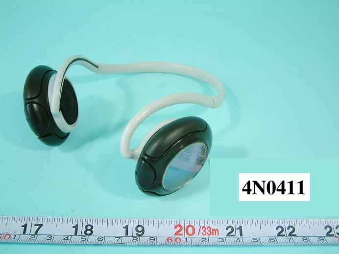
Click to zoom
Application Details
- Equipment Class
- DSS - Part 15 Spread Spectrum Transmitter
- Date of Grant
- Dec 20, 2004
- Application Purpose
- Original Equipment
- Date of Application
- Dec 20, 2004
- Equipment Note
- BLUETOOTH MP3 HEADPHONE
- Frequency Range
- 2402.00000000 - 2480.00000000
- Company
- BeCell Innovations Corp.
- Country
- Taiwan
Documents & Files
Document Text
Text extracted from the exhibit documents filed with the FCC. Open a document above to read the original.
Users Manual
Contents 1. PREFACE 01 2. INTRODUCTION 01 3. PRODUCT FEATURES 02 4. STARTING TO USE HEADPHONE 02 4.1 Package Contents 4.2 Product View 03 5. PREPARING THE BLUETOOTH MP3 HEADPHONE 04 5.1 Charging Battery 5.2 Wearing the Bluetooth MP3 Headphone 5.3 Operate Headphone 05 6. OPERATING HEADPHONE 06 6.1 Power on/off Bluetooth MP3 Headphone 6.2 Pair up with Bluetooth Mobile Phone 6.3 Using Headphone as a Bluetooth Headphone 07 6.4 Using Headphone as a FM Radio 6.5 Using Headphone as a Bluetooth Audio 08 6.6 Using Headphone as an Individual MP3 Player 6.7 Transfer Songs & Files 6.8 Firmware Upgrade 09 7. COMPATIBILITY 13 8. TROUBLE SHOOTING 13 9. WARNINGS & PRECAUTIONS 14 05 Bluetooth Headphone BMH-200 User Manual 06 English 5.3 Operate Headphone Play Use either thumb or index finger push pla y button, which is toward your right side when you are wearing the headphone. Or use your thumb to press do wnward when you hold the headset and the LCD side is face up. Increase and Decrease volume: The volume of the Bluetooth MP3 Headphone can be adjusted by pr essing the " Volume Up " or " Volume Down " buttons accordingly. Use thumb as a support point and place on the SD card, use index and middle fingers to adjust volume. Skip (FF or RW) There are two differ ent ways to operate Skip buttons: 1. To RW - use middle finger as a support point, and use thumb to press RW button. 2. To FF - use thumb as a support point, and use middle finger to press FF button. Volume Up Volume Down To RWTo FF 6. OPERATING HEADPHONE 6.1 Power on/off Bluetooth MP3 Headphone Hold down play/pause|| for 3 seconds until the LCD display “Bluetooth MP3 Headphone.” Headphone automatically will begin pla yback from the last selected mode. To power off, hold down pla y/pause|| for 3 seconds until LCD gone blank then release thump. 6.2 Pair up with Bluetooth Mobile phone EXAMPLE: Pairing with a Sony Ericsson /Ericsson Bluetooth Phone 1. Turn on your Bluetooth Headphone and mobile pone. Set the headphone to pairing-ready status. 2. Select “Connectivity” and “Y es”. 3. Select “Bluetooth” and “Y es”. 4. Select “My devices” and “Y es”; New Device”; “Searching...” appears on screen. When the mobile phone finds the Headphone, it shows the Headphone name. Select the Headphone and select ”Add to paired”. Then select “Y es” 5. When you are prompted to enter a pass key, enter passkey “0000” and select “Y es” to start the pairing process. 6. “Paring” and “Pairing succeed” messages appear on the screen. 13 Pr ess mode button 3 seconds to enter menu mode. 2 Pr ess play/pause button to enter Bluetooth mode, use FF/RW button to select “discoverable” and press play/pause button Once into discoverable there will be Headphone and HiFi option, select “Headphone”, press play button then you will hear three short beeping sound. And following the instruction of your mobile phone to pair up. 4 When the phone is success to pair up with Headphone, k ey in “0000” as pin code on the mobile phone. 3 seconds Bluetooth Enable Discoverable Set PinCode Paired Devices Discoverable Headphone HiFi Bluetooth Music FM Radio Settings Key in “0000” 07 Bluetooth Headphone BMH-200 User Manual 08 English 3 seconds 1 Pr ess mode button 3 seconds to enter menu mode. 2 Skip button to FM Radio 3 Skip button to Freq Select Mode 4 SPress Mode for three second to exit FM Radio Frequency Preset Scan 3 seconds Bluetooth Music FM Radio Settings 6.3 Using Headphone as a Bluetooth Headphone Making a call from a Bluetooth Phone You can place a phone call with your Headphone linked to your mobile phone. Use your mobile phone to dial the desired number, and then use the Bluetooth Headphone to talk and listen to the caller. If you want to use your mobile phone to talk /listen, disconnect the paired link between the Headphone and the mobile phone. Receiving a call with the Headphone When you have completed pairing the Bluetooth MP3 Headphone with your mobile phone, and have set up the link properly, y ou can use the Headphone to receive incoming phone calls. When you hear a ring tone, pr ess the play/pause button || on the Headphone to receive the incoming call. During a telephone session, if the Bluetooth Headphone exceeds the range of the operational distance, the link will be disconnected. The mobile phone will ask you if you want to resume the telephone session. If yes, the telephone will be transfer red back to the mobile phone. If no, the telephone session will be interrupted. Ending a Call from the Headphone When your telephone session is ended and the caller hangs up the Headphone and your mobile phone are ready to receive new calls and headphone will back to the last function befor e you answer the telephone. 6.4 Using Headphone as a FM radio There are three differ ent frequent select modes: Fr equency, Preset and Scan. The default setting for radio mode is Frequency. Use skip buttons FF/RW to adjust the channel. Beside frequency mode, user can also change to Preset or Scan. NOTE: The FM function is recommended to be used outside. Skip button to select either preset or scan and press play/pause MP3 WMA Do n g l e 6.5 Using Headphone as a Bluetooth Audio Pr ess “Mode” button if the Bluetooth audio icon doesn’t a ppear, r epeat until it appears. To Connect or disconnect press “play/pause” button to turn on/off Adjust volume press + or – button. If you wan to increase or decrease multiple levels of volume press and hold button until you reach the level you want. 6.6 Using Headphone as an individual MP3 player Pr ess and hold || until your headphone turns on. Pr ess || to start playing the songs that you transfer red to your SD card. Pr ess + to increase or – to decrease the volume. After you have finished using your player , press and hold || until your headphone turns off. 6.7 Transfer Songs & Files Connect our Headphone to your computer’s USB port using the supplied USB cable. Launch Windows Explorer on your computer. Your Headphone is recognized as a Removable Disk in Windows Explorer .…
Text truncated - open the document above for the full version.
External Photos
REPORT NO. : FR4N0411 SPORTON International Inc. PAGE NUMBER : A1 OF A16 TEL : 886-2-2696-2468 ISSUED DATE : Nov. 29, 2004 FAX : 886-2-2696-2255 APPENDIX A. Photographs of EUT REPORT NO. : FR4N0411 SPORTON International Inc. PAGE NUMBER : A2 OF A16 TEL : 886-2-2696-2468 ISSUED DATE : Nov. 29, 2004 FAX : 886-2-2696-2255
Internal Photos
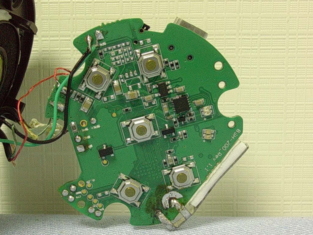
REPORT NO. : FR4N0411 SPORTON International Inc. PAGE NUMBER : A3 OF A16 TEL : 886-2-2696-2468 ISSUED DATE : Nov. 29, 2004 FAX : 886-2-2696-2255 REPORT NO. : FR4N0411 SPORTON International Inc. PAGE NUMBER : A4 OF A16 TEL : 886-2-2696-2468 ISSUED DATE : Nov. 29, 2004 FAX : 886-2-2696-2255 REPORT NO. : FR4N0411 SPORTON International Inc. PAGE NUMBER : A5 OF A16 TEL : 886-2-2696-2468 ISSUED DATE : Nov. 29, 2004 FAX : 886-2-2696-2255 REPORT NO. : FR4N0411 SPORTON International Inc. PAGE NUMBER : A6 OF A16 TEL : 886-2-2696-2468 ISSUED DATE : Nov. 29, 2004 FAX : 886-2-2696-2255 REPORT NO. : FR4N0411 SPORTON International Inc. PAGE NUMBER : A7 OF A16 TEL : 886-2-2696-2468 ISSUED DATE : Nov. 29, 2004 FAX : 886-2-2696-2255 REPORT NO. : FR4N0411 SPORTON International Inc. PAGE NUMBER : A8 OF A16 TEL : 886-2-2696-2468 ISSUED DATE : Nov. 29, 2004 FAX : 886-2-2696-2255 REPORT NO. : FR4N0411 SPORTON International Inc. PAGE NUMBER : A9 OF A16 TEL : 886-2-2696-2468 ISSUED DATE : Nov. 29, 2004 FAX : 886-2-2696-2255 REPORT NO. : FR4N0411 SPORTON International Inc. PAGE NUMBER : A10 OF A16 TEL : 886-2-2696-2468 ISSUED DATE : Nov. 29, 2004 FAX : 886-2-2696-2255 REPORT NO. : FR4N0411 SPORTON International Inc. PAGE NUMBER : A11 OF A16 TEL : 886-2-2696-2468 ISSUED DATE : Nov. 29, 2004 FAX : 886-2-2696-2255 REPORT NO. : FR4N0411 SPORTON International Inc. PAGE NUMBER : A12 OF A16 TEL : 886-2-2696-2468 ISSUED DATE : Nov. 29, 2004 FAX : 886-2-2696-2255 REPORT NO. : FR4N0411 SPORTON International Inc. PAGE NUMBER : A13 OF A16 TEL : 886-2-2696-2468 ISSUED DATE : Nov. 29, 2004 FAX : 886-2-2696-2255 REPORT NO. : FR4N0411 SPORTON International Inc. PAGE NUMBER : A14 OF A16 TEL : 886-2-2696-2468 ISSUED DATE : Nov. 29, 2004 FAX : 886-2-2696-2255 REPORT NO. : FR4N0411 SPORTON International Inc. PAGE NUMBER : A15 OF A16 TEL : 886-2-2696-2468 ISSUED DATE : Nov. 29, 2004 FAX : 886-2-2696-2255 REPORT NO. : FR4N0411 SPORTON International Inc. PAGE NUMBER : A16 OF A16 TEL : 886-2-2696-2468 ISSUED DATE : Nov. 29, 2004 FAX : 886-2-2696-2255
Operational Description
Operational Description 1. GDM1202 The GDM1202 is a part of the GCT Bluetooth product family. It is a DSP processor with the functionality of both baseband controller providing the Bluetooth™ functionality for high data rate, short-distance wireless communication in the free 2.4GHz ISM band and digital audio decoder such as MP3 or AC3. Together with GDM100X 2.4GHz radio transceiver IC and an external flash memory, it provides a fully compliant Bluetooth system for data and voice communications. GDM1202 consists of BlueRF™ RXMODE2/3, 3-wires radio interface, Bluetooth™ baseband and bit processor, GCT proprietary 32-bit hybrid RISC/DSP embedded processor with 48bit resolution, and USB / UART / PCM / DAC / I2S / SPDIF / SMC standard interfaces. The on-chip 32-bit hybrid RISC/DSP embedded processor is powerful enough to support full rate Bluetooth data communications as well as full rate digital audio decoding and includes large enough embedded SRAM up to 128KByte to support several applications without external memory, which results in cost-effective and low-power consumption systems. In combination with GCT own optimized Bluetooth™ baseband, embedded protocol stacks and audio decoder firmware, it provides a complete cost-effective SOC embedded solutions such as portable MP3 decoder, wireless high quality speaker system or headset. 2. GDM1002 The GDM1002 is a part of the GCT Bluetooth product family. It is a short-range microwave-frequency radio transceiver for Bluetooth links that operates in the 2.4 GHz ISM band. The device consists of a fully integrated 2.4 GHz radio transceiver with GFSK modem. This radio IC is based on GCT’s proprietary radio architecture employing direct conversion scheme, which offers superior channel selectivity, and is implemented in CMOS technology, which provides low cost integrated RF and baseband solutions for Bluetooth applications. The GDM1002 incorporates the complete receive and transmit components including PLL, VCO, LNA, up/down converter, channel select filters, and digital GFSK modem. 3. STw5094 STw5094 is a low power Stereo Audio DAC device with Headphones Amplifiers for high quality MP3 and FM radio listening. The STw5094 includes also an high performance low power combined PCM CODEC ⁄ FILTER tailored to implement the audio front-end functions required by low voltage low power consumption digital cellular terminals with added MP3 and FM radio listening. STw5094 offers a number of programmable functions accessed through an I2C-bus compatible interface. The STw5094 Stereo Audio DAC section is suited for MP3, or any other audio stereo source, listening. It supports all the MP3 rates from 8kHz to 48kHz. The audio data serial interface is I2S compatible and can be programmed to handle 16 to 24 bit word length input data. The internal D to A converters work with 18bit input resolution. The Stereo Headphones drivers can also be used for FM Radio listening via an auxiliary stereo analog input. A Loudspeaker driver can also be used for monophonic group listening. The STw5094 Voice Codec section can be configured either as a 14-bit linear or as an 8-bit companded PCM coder. The Frame Synchronism frequency of the Voice Codec can be either the standard 8kHz value or the extended 16kHz one. In addition to the Stereo Audio DAC and CODEC ⁄ FILTER functions, STw5094 includes a Tone ⁄ Ring ⁄ DTMF generator that can be used both in Audio Listening mode and in Voice Codec mode, a sidetone generation, a buzzer driver output and a remote control function tailored to handle an external on-hook off-hook button. STw5094 Voice Codec fulfills and exceeds D3 ⁄ D4 and CCITT recommendations and ETSI requirements for digital handset terminals. The Stereo Audio DAC part fulfills and exceeds the requirements for MP3 quality and FM radio quality listening. Main applications include digital mobile phones, as cellular and cordless phones, with added low-power high-quality MP3 and ⁄ or FM radio listening features, or any battery powered equipment that requires Stereo Audio DAC with Headphones drivers operating at low single supply voltage. 4. 16Mbits FLASH M29W160DB The M29W160D is a 16 Mbit (2Mb x8 or 1Mb x16) non-volatile memory that can be read, erased and reprogrammed. These operations can be performed using a single low voltage (2.7 to 3.6V) supply. On power-up the memory defaults to its Read mode where it can be read in the same way as a ROM or EPROM. The memory is divided into blocks that can be erased independently so it is possible to preserve valid data while old data is erased. Each block can be protected independently to prevent accidental Program or Erase commands from modifying the memory. Program and Erase commands are written to the Command Interface of the memory. An on-chip Program/Erase Controller simplifies the process of programming or erasing the memory by taking care of all of the special operations that are required to update the memory contents. The end of a program or erase operation can be detected and any error conditions identified. The command set required to control the memory is consistent with JEDEC standards. The blocks in the memory are asymmetrically arranged, see Figures 6 and 7, Block Addresses. The first or last 64 Kbytes have been divided into four additional blocks. The 16 Kbyte Boot Block can be used for small initialization code to start the microprocessor, the two 8 Kbyte Parameter Blocks can be used for parameter storage and the remaining 32K is a small Main Block where the application may be stored. Chip Enable, Output Enable and Write Enable signals control the bus operation of the memory. They allow simple connection to most microprocessors, often without additional logic. The memory is offered in SO44, TSOP48 (12 x 20mm) and TFBGA48 (8 x 9mm, 0.8mm pitch) packages. The memory is supplied with all the bits erased (set to ’1’). 5. SRAM GS74116A The GS74116A is a high speed CMOS Static RAM organized as 262,144 words by 16 bits. Static design…
Text truncated - open the document above for the full version.
Test Report
FCC ID: SRFBECELLBMH200 Issued on Nov. 29, 2004 Report No.: FR4N0411 SPORTON International Inc. TEL : 886-2-2696-2468 FAX : 886-2-2696-2255 FCC TEST REPORT CATEGORY : Portable PRODUCT NAME : Bluetooth MP3 Headphone FCC ID. : SRFBECELLBMH200 FILING TYPE : Certification MODEL NAME : BMH-200 APPLICANT : BeCell Innovations Corp 12F-9, No. 79, Shin- Tai 5th Rd. Sec. 1, Shih-Chih, Taipei 221, Taiwan MANUFACTURER : Same as applicant ISSUED BY : SPORTON INTERNATIONAL INC. 6F, No. 106, Sec. 1, Hsin Tai Wu Rd., His Chih, Taipei Hsien, Taiwan, R.O.C. Statements: The test result in this report refers exclusively to the presented test model / sample. Without written approval of SPORTON International Inc., the test report shall not be reproduced except in full. Certificate or Test Report could not be used by the applicant to claim the product endorsement by CNLA, NVLAP or any agency of U.S. government. The test equipment used to perform the test are calibrated and traceable to NML/ROC or NIST/USA. Dr. Alan Lane Vice General Manager Sporton International Inc. Lab Code: 200079-0 FCC ID: SRFBECELLBMH200 Issued on Nov. 29, 2004 Report No.: FR4N0411 SPORTON International Inc. Page No. : i TEL : 886-2-2696-2468 Issued Date : Nov. 29, 2004 FAX : 886-2-2696-2255: Table of Contents History of this test report....................................................................................................................................ii CERTIFICATE OF COMPLIANCE.......................................................................................................................iii 1. General Description of Equipment under Test.............................................................................................1 1.1. Applicant ......................................................................................................................................................................................... 1 1.2. Manufacturer ................................................................................................................................................................................... 1 1.3. Basic Description of Equipment under Test.................................................................................................................................... 1 1.4. Features of Equipment under Test ................................................................................................................................................. 1 1.5. Antenna Description........................................................................................................................................................................ 2 1.6. Table for Carrier Frequencies ......................................................................................................................................................... 2 2. Test Configuration of the Equipment under Test.........................................................................................3 2.1. Connection Diagram of Test System .............................................................................................................................................. 3 2.2. The Test Mode Description............................................................................................................................................................. 3 2.3. Description of Test Supporting Units .............................................................................................................................................. 3 3. General Information of Test............................................................................................................................4 3.1. Test Facility ..................................................................................................................................................................................... 4 3.2. Test Conditions ............................................................................................................................................................................... 4 3.3. Standards for Methods of Measurement......................................................................................................................................... 4 3.4. DoC Statement ............................................................................................................................................................................... 4 3.5. Frequency Range Investigated ....................................................................................................................................................... 4 3.6. Test Distance .................................................................................................................................................................................. 4 3.7. Test Software .................................................................................................................................................................................. 4 4. List of Measurements......................................................................................................................................5 4.1. Summary of the Test Results.......................................................................................................................................................... 5 5. Test Result .......................................................................................................................................................6 5.1. Test of Hopping Channel Bandwidth .............................................................................................................................................. 6 5.2. Test of Hopping Channel Separation.............................................................................................................................................. 9 5.3.…
Text truncated - open the document above for the full version.
Test Setup Photos
Powered by adapter FRONT VIEW REAR VIEW Powered by USB FRONT VIEW REAR VIEW Powered by adapter FRONT VIEW REAR VIEW Powered by USB FRONT VIEW REAR VIEW
Contact Information
Applicant
Charlie Chen(Account Manager)
Test Firm
SPORTON International IncKathy Lin
Technical Specifications
| # | Rule Parts | Frequency Range | Power Output |
|---|---|---|---|
| 1 | 15C | 2.40 GHz - 2.48 GHz | 2.88 mW |
Other Applications from BeCell Innovations Corp.
SRF0219082XX
Jul 04, 2006Bluetooth Audio Streaming Headphone
Equipment Class
DSS - Part 15 Spread Spectrum Transmitter
SRFBCBTH200
May 10, 2005Headset with Bluetooth Technology
Equipment Class
DSS - Part 15 Spread Spectrum Transmitter