SRMT11006740Temperature Monitor
Sensitech, INC.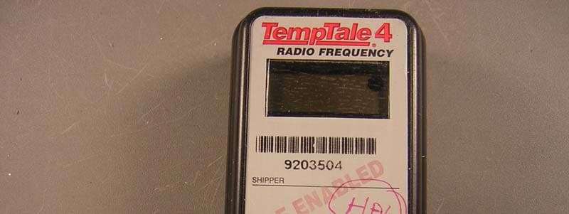
Click to zoom
Application Details
- Equipment Class
- DXX - Part 15 Low Power Communication Device Transmitter
- Date of Grant
- Jul 07, 2005
- Application Purpose
- Original Equipment
- Date of Application
- Jul 07, 2005
- Equipment Note
- Temperature Monitor
- Frequency Range
- 914.80000000 - 927.60000000
- Company
- Sensitech, INC.
- Country
- United States
Documents & Files
Document Text
Text extracted from the exhibit documents filed with the FCC. Open a document above to read the original.
Users Manual
RF TT4 Ambient 2K Monitor PN T11006740 User Manual Millions Depend on the Inte grity of Your Pr oduct. Sensitech’s Mission is to Ensure that Integrit y . The Tools That Turn In formation Into Power FCC ID SRMT11006740 Te m p Tale ® Man a ger So f t ware Data Manage m e n t Serv ices Te m p Tale ® 3 Monitor Te m p Tale ® 4 M onitor R F M onitor i ng Tag A lert ™ Monito r This d e vice complies with Part 15 of the FCC Rules. Operation is subject to the following two condi ti ons: ( 1 ) this device may not cause har mful i n terference, and ( 2 ) this device must accept any interference received, including i n terference that may cause undesired operation. Changes or modif i cations not expressly approved by Sensitech could void the user ’s authori t y to operate the equipment. For more information, cont act our client servi c es gr oup at 800- 843-8367. Sensitech In c. • 800 Cummings Ce nter • B everl y , MA 0191 5 (978) 927-7 033 • Fax (9 78) 921 -2112 www.sensitech. com © 200 5 A l l R i ghts Re serv ed. T e mp T a l e i s a r e g i stered tr ademar k and TagAl e r t i s a tr ademar k o f Sensi t ech, Inc . 800 C u mmi n g s C e nter , Bev e rly , M A 01915 T1 1006 740 Start i ng a Tem p Tale4 Moni tor • P ress and rele a s e the Start but t on. • T he “Su n s h i n e” icon app ears in the upper left corner of th e d i sp lay. • T he Tem p Tale4 wi l l begi n t o record dat a after t h e st art-up del a y has pass ed. Inic iar e l TempTale4 • P resion e y lib ere e l b o t ó n d e i n icio “Start”. • E l i c on de l “ S ol ” a p a r ecerá a la i z qui e r da e n l a pa rte su peri or de l a pant al l a . • E l Te m p Tale4 grabar á d espúes d el tiem p o d e dem u r a . Pantalla del Monitor: All Tem p Tale ® 4 Mon i to rs are pr og ram m e d wit h a cust om Sta r t-u p de la y , m easurem e nt inte rva l and a l arm se tting s which have been pre-dete rm ined by the cus t om er. To mark an important e v ent (“Date St amp”) • T em pTale4 m oni t o rs pr o v i d e an o p t i on to “Date Stam p” or mark an im p o rtant ev en t at an y time d u r ing t h e m o n ito ri n g cy c l e th at will b e v i si b l e wh en v i ewin g t h e dat a . The m a rk i s di sp l a yed as an arrow when v i ewi n g t h e graph an d s how n in italics wh en v i ewin g t h e ta b u l ar d a ta. • T o m a rk a g r a p h while th e mo n i to r is r ecording, press and rele as e the “Start” but t o n. • T h e “ a r r o w ” ic o n will ap p ear te m p o r arily in th e lo wer left c o rn er an d t h e t e m p er at ure hi st ory wi l l appear on t h e di s p l a y . Data appears as fol l ows: Alarm 1. Average t e mperat ure 2. Hi ghest t e m p erat ure recorded 3 . To tal time ab o ve h i gh tempera t u r e limit 4. Lowest temperat ure recorded 5 . To tal time belo w l o w temp era t u r e limit W h en t h e Te mpTale4 is exposed to a te m p er at ure out si de a pre-program m e d l i m i t an d tim e th res h o l d , an “Alar m b e ll ” wi ll ap p ear in th e lo wer righ t corn er o f th e LCD dis p lay. Stopp i ng a TempTale4 Moni tor Press an d hol d (1 t o 3 second s ) t h e St o p b u t t on u n t i l t h e “St o p si g n ” i c on appears i n t h e up per ri ght corner of t h e LC D di spl a y . St o pped recordingLim its e x cee de d Mar k ed Po in t Recording Displayed Information Te m p er ature data Para marcar un evento importante (Estampa de fecha) • L os Tem p Tale4 m oni t o res t i e nen l a opci ó n d e m a r c ar un event o i m port a nt e que occur a durant e el envi o. Se puede ver est a m a r c a c uando se baja l a i n form aci ón. La m a r c a a par ecer á co m o u n a f l echa e n el grafíco y en italico e n el tab u l ar. • P ara m a r c ar el event o d u rant e e l envi o, presi one y l i ber e el bot ó n de in icio “Start”. • U na fl ec ha a p arecerá e n l a pant a l l a y l a i n form ac i ó n d e t e m p e r a t ura apa r e c e r á en el si guente o rden: 1. Temperat ur a p r o medi o 2. Temperat ur a g r a b a d a m ás al t a 3 . Tiempo t o t a l po r e n c ima d el límite a lto 4. Temperat ur a g r a b a d a m ás b a j a 5 . Tiempo t o t a l ba j o d e l límit e b a j o AlarmaCu and o el Te m p T a le4 est á f u er a d el lím it e b aj o o alto d e l tie m p o p rog r a m ad o , un i c on de al ar m a aparecer á a l a der echa e n l a parte b aja d e l a pantal l a . Parar e l TempTale4 Presi o ne y l i b ere ( 1 a 3 segu n d o s ) el b o t ó n d e par a r “ St o p ” hast a que el i c on de “ S t o p” a p a r ezca a l a derec h a e n l a pa rte s upe ri or de l a pa nt a l la . ParadoAlar m a Mar c a d e eventoIn iciad o Inform ación d e tem p er atur a Los m oni tore s d e Tem p Tale ® 4 están p r o g ram a do con uno t i em po d e dem u ra, intervalo y lim i tes d e tem p era t ura y tiem po que f ueron r equie r ido p o r el cli e nt e .
Cover Letter(s)
Response to TCB Findings 1. On Pg 8 of the report, a channel at 905.4MHz appears to be active on the supplied plots. This channel has not been listed in the report and does not seem to be tested. Please clarify. When operating at a very wide frequency span, the marker frequency can be off by several MHz, which is why the plot appears to show a channel where there is none. Their channels are in the following order: CH1 @ 914.85MHz (tested) CH2 @ 922MHz (tested) CH3 @ 927.56MHz (tested) 2. Please confirm that the antenna is part of the Tx PCB and not a separate element. The antenna is a small 2-pin plate that was removed from the PCB to do conducted output testing. 3. Please specify the dimensions of the device, as compliance statement of 15.19(a)(3) is not on the label. The Device is 2"Wx4"H
External Photos
External Pictures
ID Label/Location Info
RF ENABLED PO#: Shipping 7 Connector Road • Mailing P.O. Box 4247 • Andover, MA 01810 Phone [978] 474-1930 • Fax [978] 474-1931 • Internet www.reidgraphics.com INSPECT THIS PROOF CAREFULLY...This proof represents our interpretation of your instructions and/or artwork. Your order will be manufactured according to the information provided on this proof. Please check copy, color breaks, size and overall design for errors. Reid Graphics will assume no liability for parts manufactured according to the information herein once this proof is signed by the customer. PLEASE NOTE: The intention of this proof is to show color breaks and approximate color only (If multi-color). It is not intended to represent actual color match. ATTN: FROM: APPROVED customer signature customer signature NOT APPROVED COMMENTS: Sensitech 65211-RC 1.516”3.090”.140 9/16/04TD-FH1 of 1 Red 186 Green 348 Black Cool Grey 5 REID GRAPHICS FRONT LABEL BACK LABEL FCC ID SRMT11006740 0153931 SHIPPER P.O. NO. Start Stop Sensitech Inc. 800 Cummings Center, Suite 258x, Beverly, MA 01915 USA (978) 927-7033 (800) THE-TEMP T17004890 Rev: A ® 4 RADIO FREQUENCY C. KELLEY 4 T17004890 Rev A
Internal Photos
Internal Pictures
Test Report
Test Report Report No . EE0881-1 Client Sensitech, INC. 800 Cummings Center, Suite 258X Beverly, MA 01915 Phone 978-720-2593 Fax 978-921-2112 FRN 0011744471 Models T11006740 FCC ID SRMT11006740 Equipment Type Low Power Communication Device Transmitter Equipment Code DXX Results As detailed within this report Prepared by Mairaj Hussain – Test Engineer Authorized by Michael Buchholz – EMC Manager Issue Date 3/1/05 Conditions of issue This Test Report is issued subject to the conditions stated in ‘terms and conditions’ section of this Curtis-Straus LLC is accredited by the American Association for Laboratory Accreditation for the specific scope of accreditation under Certificate Number 1627-01. This report may contain data which is not covered by the A2LA accreditation. _____________________________________________________________ LLC • 527 Great Road • Littleton, MA • TEL (978) 486-8880 • FAX (978) 486-8828 Curtis-Straus REPORT:EE0881-1 FCC ID:SRMT11006740 _____________________________________________________________ Curtis-Straus Summary...........................................................................................................3 Test Methodology..............................................................................................3 EUT Configuration.............................................................................................4 Statement of Conformity....................................................................................5 Test Data and Plots...........................................................................................6 Section 15.249 (b).........................................................................................6 Section 15.249 (b) (1)....................................................................................6 Section 15.249 (d).........................................................................................8 Occupied Bandwidth....................................................................................11 Test Equipment Used......................................................................................12 Terms And Conditions.....................................................................................16 A2LA Accreditation..........................................................................................18 LLC • 527 Great Road • Littleton, MA • TEL (978) 486-8880 • FAX (978) 486-8828 Page 2 of 20 REPORT:EE0881-1 FCC ID:SRMT11006740 _____________________________________________________________ Curtis-Straus Summary This report is an application for certification of a transmitter operating under 47 CFR 15.249 of the FCC rules provided for operation in the frequency band of 902-928MHz. The product covered by this report is T11006740, which is a Digital Relay Radio System (DRRS). The manufacture requires the following antenna to be used with T11006740: i) Ember antenna part number: 1513382-1 A detailed description of the above-mentioned antenna can be found in the antenna exhibit. Test Methodology All testing was performed according to the procedures specified in ANSI C63.4 (2003). The product was tested with modulation on and peak readings were compared against the average limit presented in section CFR 15.249. Spurious emissions in the frequency range of 30MHz- 1000MHz were checked in an anechoic chamber. Frequency range investigated: 30MHz – 10GHz Measurement Distance: Frequency (MHz) Distance (m) Comments Fundamental (Three channels) 914.92, 922, & 927.56 MHz 3 m Radiated 30MHz – 10GHz except 902 - 928 MHz band 3m Radiated Spurious Measurements The EUT was fully maximized. The EUT antenna can not be maximized separately. The product was evaluated at three channels of operation. (Channel 1, Channel 2, and Channel 3.) The product is battery powered, therefore no AC conducted emissions were performed. All readings are peak unless otherwise noted. LLC • 527 Great Road • Littleton, MA • TEL (978) 486-8880 • FAX (978) 486-8828 Page 3 of 20 REPORT:EE0881-1 FCC ID:SRMT11006740 _____________________________________________________________ Curtis-Straus EUT Configuration Product Name: RF TT4 Ambient 2K Monitor Part Number: T11006740 Serial Number: 1427400050 EUT Cables: None EUT Power Source: Battery (fresh battery used for testing) Environmental Conditions November 8, 2004: 24.1°C; 22%RH Standard Operating Voltage 3.6VDC (lithium battery) LLC • 527 Great Road • Littleton, MA • TEL (978) 486-8880 • FAX (978) 486-8828 Page 4 of 20 REPORT:EE0881-1 FCC ID:SRMT11006740 _____________________________________________________________ Curtis-Straus Statement of Conformity The T11006740 has been found to conform with the following parts of the 47 CFR as detailed below: 47 CFR Part # 47 CFR Part # RSS- 210 Comments 15.15(b) 5.7 The product contains no user accessible controls that increase transmission power above allowable levels. 2.925 15.19 5.10 The label is shown in the label exhibit. The label is permanently attached. 15.21 5.11 Information to the user is shown in the instruction manual exhibit. 15.27 No special accessories are required for compliance. 15.31(e) Voltage variation test was not performed on the product because it drives power from a battery. 15.203 5.5 The device utilizes antenna specific to the product. 15.204 5.5 See attached documentation describing the antenna. 15.205 15.209 6.2.1 The fundamental is not in a Restricted band and the spurious comply with the general emission limits of 15.209. 15.207 6.6 Unit is DC powered and drives its power from a battery, therefore AC line conducted emissions testing was not done. 15.249 15.249 (a) 6.2.2 The EUT meets the field strength limit of 50mV/m (94dBμV/m) at the fundamental. 15.249 (d) 6.2.1 Spurious emissions meet the general radiated emissions limits of section 15.209. 15.249 (e) 6.2.1 Spurious emissions found above 1GHz meet the FCC class B limits. 5.9.1 Emission bandwidth plot is provided with this report. LLC • 527 Great R…
Text truncated - open the document above for the full version.
Test Setup Photos
Set UP Pictures
Contact Information
Applicant
Eric Day
Test Firm
BUREAU VERITAS CONSUMER PRODUCTS SERVICES, INC.Ozgur Ozturk
[email protected]978-486-8880
Technical Specifications
| # | Rule Parts | Frequency Range | Power Output |
|---|---|---|---|
| 1 | 15C | 914.8 MHz - 927.6 MHz | - |
Other Applications from Sensitech, INC.
SRMT11012920
Jul 30, 2022Sensor
Equipment Class
DSS - Part 15 Spread Spectrum TransmitterSRMT11012860
Jul 30, 2022Quarterback Gateway
Equipment Class
DTS - Digital Transmission System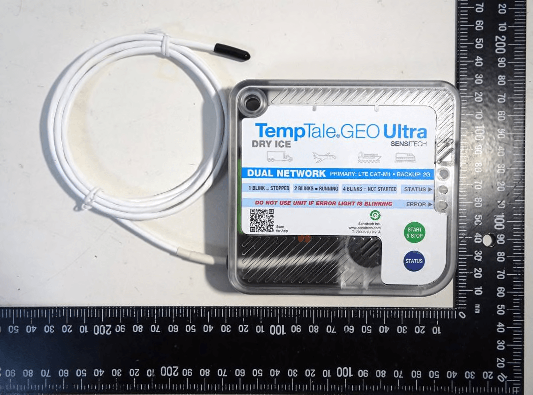
SRM-120866SST
Jan 04, 2021Temp/Humidity Data Logger / Tracker
Equipment Class
DXT - Part 15 Low Power Transceiver, Rx Verified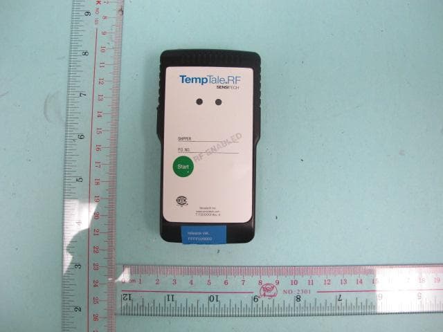
SRMT11012294
Dec 07, 2014TempTale RF2 Datalogger, RF Temperature Monitor
Equipment Class
DXX - Part 15 Low Power Communication Device Transmitter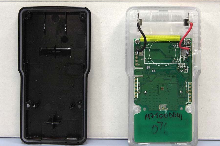
SRMT11012177
Aug 15, 2010TEMPTALE4 RF MONITOR STORES TEMPERATURE VALUES, IDENTIFIES LOCATIONS TRAVELED THROUGH AND STORES SHIPMENT INFORMATION. ALL OF THIS INFORMATION CAN BE TRANSMITTED WIRELESSLY TO A LOCAL COMPUTER.
Equipment Class
DXX - Part 15 Low Power Communication Device Transmitter