SRMT11012294TempTale RF2 Datalogger, RF Temperature Monitor
Sensitech, INC.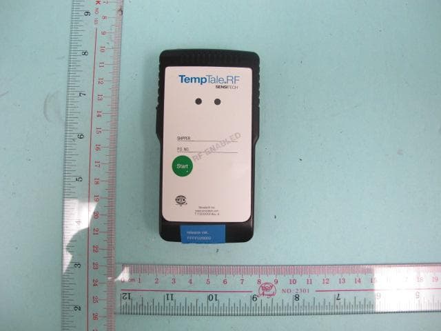
Click to zoom
Application Details
- Equipment Class
- DXX - Part 15 Low Power Communication Device Transmitter
- Date of Grant
- Dec 07, 2014
- Application Purpose
- Original Equipment
- Date of Application
- Dec 06, 2014
- Equipment Note
- TempTale RF2 Datalogger, RF Temperature Monitor
- Frequency Range
- 921.50000000 - 924.50000000
- Company
- Sensitech, INC.
- Country
- United States
Documents & Files
Document Text
Text extracted from the exhibit documents filed with the FCC. Open a document above to read the original.
Users Manual
TempTale ® RF 2 System Installation Manual T82003843 Revision 7 April 29, 2014 Table of Contents 1. Overview of the TempTale RF 2 System ................................................................................................. 1 1.1. Important Installation Notes ......................................................................................................... 3 1.2. Mounting the Gateway and Repeater .......................................................................................... 4 2. TempTale RF 2 Gateway ......................................................................................................................... 6 2.1. Gateway Components ................................................................................................................... 6 2.2. Gateway Assembly ........................................................................................................................ 7 2.3. RF 2 Gateway Specifications ........................................................................................................... 9 3. TempTale RF 2 Repeater ....................................................................................................................... 10 3.1. Repeater Components ................................................................................................................ 10 3.2. Repeater Assembly ..................................................................................................................... 11 4. Repeater Specifications ...................................................................................................................... 12 5. TempTale RF 2 Datalogger .................................................................................................................... 13 5.1. Datalogger Components ............................................................................................................. 13 5.2. RF Auto-Roaming ........................................................................................................................ 13 5.3. Logging Data ................................................................................................................................ 14 5.4. Alarms ......................................................................................................................................... 14 5.5. Datalogger Specifications ............................................................................................................ 15 6. TempTale RF 2 Gateway Software ........................................................................................................ 16 6.2. Windows Services \ Applications ................................................................................................ 16 Sensitech Network Manager ............................................................................................................... 16 Sensitech Rule Manager ..................................................................................................................... 16 DataTransporter .................................................................................................................................. 17 Configuration Utilities ......................................................................................................................... 17 Sensitech Rule Viewer ......................................................................................................................... 17 Sensitech Manual API Updater ........................................................................................................... 17 Declaration of Conformity (DoC) ................................................................................................................ 18 FCC Statement ............................................................................................................................................ 19 Industry Canada Statement ........................................................................................................................ 19 Sensitech TempTale RF 2 System Installation Manual Revision 7 Page 1 1. Overview of the TempTale RF 2 System The TempTale ® RF 2 system consists of infrastructure components and dataloggers. The infrastructure components, TempTale RF 2 Gateways (Gateways) and TempTale RF 2 Repeaters (Repeaters), are installed permanently while the TempTale RF 2 Dataloggers(Dataloggers) travel with the cargo and report their data when they arrive at a location that has an installed TempTale RF 2 infrastructure. This manual presents information relevant to Sensitech personnel who have been trained to install the TempTale RF 2 system. Each location can only have one Gateway installed but many Repeaters. The Gateway receives and sends data to and from Repeaters using RF signals and also connects to the Internet to make this data widely available. Repeaters receive and send data or commands to the TempTale RF 2 Dataloggers through RF signals. The infrastructure devices, the TempTale RF 2 Gateway and TempTale RF 2 Repeaters, communicate with each other at 2.4 GHz frequencies. However, the system can accommodate smaller installations as the Repeaters and Gateways can also communicate directly with the TempTale RF 2 Dataloggers at 868 MHz or 915 MHz frequencies. This unique feature makes the infrastructure scalable and flexible for use at large or small installations. The Gateway consists of a ruggedized, embedded computer loaded with the programs required to read, process the data and connect to the Internet. The Gateway programs also performs data buffering and error checking and data decryption to insure data integrity. Sensitech TempTale RF 2 System Installation Manual Revision 7 Page 2 The layout of the system can be viewed as a tree with the Gateway as the root and Repeaters as nodes. When planning for the layout of the TempTale …
Text truncated - open the document above for the full version.
External Photos
Appendix B Date: 2014-04-10 Report No.: 60.870.14.008.01F Model No.:TempTaleRF 2 Datalogger Page 1 of 3 TÜV SÜD Hong Kong Ltd. 3/F, West Wing, Phase 2, 10 Science Park West Avenue, Shatin, Hong Kong. Appendix B Date: 2014-04-10 Report No.: 60.870.14.008.01F Model No.:TempTaleRF 2 Datalogger Page 2 of 3 TÜV SÜD Hong Kong Ltd. 3/F, West Wing, Phase 2, 10 Science Park West Avenue, Shatin, Hong Kong. Appendix B Date: 2014-04-10 Report No.: 60.870.14.008.01F Model No.:TempTaleRF 2 Datalogger Page 3 of 3 TÜV SÜD Hong Kong Ltd. 3/F, West Wing, Phase 2, 10 Science Park West Avenue, Shatin, Hong Kong.
ID Label/Location Info
This device complies with Part 15 of the FCC Rules.Operation is subject to the following two condition s: (1) This device may not cause harmful interference , and (2) This device must accept any interference recei ved, including interference that may cause undesired ope ration. MADE IN CHINA FCC ID: SRMT11012294 IC: 6654A-11012294 MODEL: TempTale RF 2 Datalogger US PAT #RE.36,200 Sensitech Inc.
ID Label/Location Info
Label Position
Internal Photos
Appendix C Date: 2014-04-10 Report No.: 60.870.14.008.01F Model No.:TempTaleRF 2 Datalogger Page 1 of 2 TÜV SÜD Hong Kong Ltd. 3/F, West Wing, Phase 2, 10 Science Park West Avenue, Shatin, Hong Kong. Appendix C Date: 2014-04-10 Report No.: 60.870.14.008.01F Model No.:TempTaleRF 2 Datalogger Page 2 of 2 TÜV SÜD Hong Kong Ltd. 3/F, West Wing, Phase 2, 10 Science Park West Avenue, Shatin, Hong Kong.
RF Exposure Info
Date: 2014-04-10 Report No.: 60.870.14.008.01S Model No.:TempTaleRF 2 Datalogger Page 1 of 1 TÜV SÜD Hong Kong Ltd. 3/F, West Wing, Phase 2, 10 Science Park West Avenue, Shatin, Hong Kong. SAR Evaluation Exemption Compliance Information The device has a standalone transmission. According to KDB 447498 section 4.3.1, the 1-g SAR test exclusion thresholds at test separation distances 50 mm are determined by: [(max. power of channel, including tune-up tolerance, mW)/(min. test separation distance, mm)]·[ ¥f(GHz)] 3.0 The maximum tune-up limit power is 0.373 mW @ 0.924 GHz For the head and body SAR, use 50mm as the conservative minimum test separation distance, [(max. power of channel, including tune-up tolerance, mW)/(min. test separation distance, mm)]·[ ¥f(GHz)] = 0.0078 3.0 So standalone SAR measurements are not required for both head and body
Test Report
TEST REPORT Date: 2014-04-10 Report No.: 60.870.14.008.01F Page 1 of 22 TÜV SÜD Hong Kong Ltd. 3/F, West Wing, Phase 2, 10 Science Park West Avenue, Shatin, Hong Kong. Applicant: Sensitech Inc. 800 Cummings Ctr, Suite 258X Beverly, MA 01915-6197, USA Description of Samples:Model name: TempTale RF 2 Datalogger, RF Temperature Monitor Brand name: --- Model no.: TempTale RF 2 Datalogger FCCID:SRMT11012294 Date Samples Received:2014-03-06 Date Tested:2014-03-07 to 2014-04-09 Investigation Requested:FCC Part 15 Subpart C, Section 15.249 Conclusions:The submitted product COMPLIED with the requirements of Federal Communications Commission [FCC] Rules and Regulations Part 15. The tests were performed in accordance with the standards described above and on Section 2.2 in this Test Report. Remarks:---- Checked by:Approved by:- Ray CheungJeff Pong Project EngineerOperation Manager Wireless & Telecom departmentWireless & Telecom department Report No.: 60.870.14.008.01F Page 2 of 22 TÜV SÜD Hong Kong Ltd. 3/F, West Wing, Phase 2, 10 Science Park West Avenue, Shatin, Hong Kong. CONTENT: Cover Page 1 of 22 Content Page 2 of 22 1.0General Details 1.1Test Laboratory Page 3 of 22 1.2Applicant Details Page 3 of 22 1.3Equipment Under Test [EUT] Page 4 of 22 1.4 Equipment Modification Page 4 of 22 1.5 Related Submittal(s) Grants Page 4 of 22 2.0Technical Details 2.1Investigations Requested Page 5 of 22 2.2Test Standards and Results Summary Page 5 of 22 3.0Test Methodology 3.1Radiated Emission Page 6 of 22 3.2Field Strength Calculation Page 6 of 22 3.3Conducted Emission Page 6 of 22 4.0Test Results 4.1Field Strength of Fundamental and Harmonics Page 7-9 of 22 4.2Spurious Radiated Emission Page 10-15 of 22 4.3Out of Band Emissions Page 16-17 of 22 4.4Bandwidth Measurement Page 18-20 of 22 4.5Conducted Emission Page 21 of 22 5.0List of Measurement Equipments Page 22 of 22 Appendix A Photos of Test Setup Appendix B External EUT Photos Appendix C Internal EUT Photos Report No.: 60.870.14.008.01F Page 3 of 22 TÜV SÜD Hong Kong Ltd. 3/F, West Wing, Phase 2, 10 Science Park West Avenue, Shatin, Hong Kong. 1.0General Details 1.1Test Laboratory Attestation of Global Compliance Co., Ltd 1&2F, No. 2 Building, Huafeng No.1 Industrial Park, Gushu Community Xixiang Street, Bao’an District, Shenzhen, China Registration Number: 259865 Tested by: John Zhi 1.2Applicant Details Applicant Sensitech INC. 800 Cummings Ctr, Suite 258X Beverly, MA 01915-6197, USA. Manufacturer Blue Ocean Innovation Ltd. RM 1813, Fo Tan Indus. Ctr. 26 – 28 Au Pui Wan Street, Fotan, HK. Report No.: 60.870.14.008.01F Page 4 of 22 TÜV SÜD Hong Kong Ltd. 3/F, West Wing, Phase 2, 10 Science Park West Avenue, Shatin, Hong Kong. 1.3Equipment Under Test [EUT] Description of EUT Model Name:TempTaleRF 2 Datalogger, RF Temperature Monitor Brand Name: --- Model Number: TempTale RF 2 Datalogger FCCID:SRMT11012294 Rating:3 VDC (1 x 3V “CR123A” Lithium battery) Antenna Type:Integral Operated Frequency:921.5MHz to 924.5MHz No. of Channel:3(921.5 MHz, 923.5 MHz and 924 MHz) Accessories and Auxiliary Equipment:None EUT Exercising Software:None General Operation of EUT The Equipment Under Test (EUT) is a Monitor with RF temperature Sensor operated at 921.5 MHz to 924.5 MHz. 1.4Equipment Modification No modification was made to the tested unit by TÜV SÜD Hong Kong Ltd. 1.5Related Submittal(s) Grants This is a single application of certification for this transmitter. Report No.: 60.870.14.008.01F Page 5 of 22 TÜV SÜD Hong Kong Ltd. 3/F, West Wing, Phase 2, 10 Science Park West Avenue, Shatin, Hong Kong. 2.0Technical Details 2.1Investigations Requested Perform ElectroMagnetic Interference measurement in accordance with FCC 47CFR [Codes of Federal Regulations] Part 15: 2012 and ANSI C63.4: 2009. 2.2Test Standards and Results Summary Tables EMISSION Results Summary Test ConditionFCC TestTest Result RequirementPassFailedN/A Field Strength of Fundamental and Harmonics Part 15.249 (a),(e) Spurious Radiated Emission Part 15.249 (d) Part 15.209 Part 15.205 Out of Band EmissionsPart 15.249 (d) Bandwidth Measurement Part 15.215 (c) Conducted EmissionPart 15.207 Note: N/A - Not Applicable Report No.: 60.870.14.008.01F Page 6 of 22 TÜV SÜD Hong Kong Ltd. 3/F, West Wing, Phase 2, 10 Science Park West Avenue, Shatin, Hong Kong. 3.0Test Methodology 3.1Radiated Emission The sample was placed 0.8m above the ground plane on astandard emission test site *. Measurements in both horizontal and vertical polarities were performed. During the test, each emission was maximized by: having the EUT continuously working, investigated all operating modes, rotated about all 3 axis (X, Y & Z) and considered typical configuration to obtain worst position, manipulating interconnecting cables, rotating turntable, varying antenna height from 1m to 4m in both horizontal and vertical polarizations. The emissions worst-case are shown in Test Results of the following pages. 3.2Field Strength Calculation The field strength at 3 m was established by adding the meter reading of the spectrum analyzer to the factors associated with antenna correction factor, cable loss, preamplifiers and filter attenuation. The equation is expressed as follow: FS = R + System Factor System Factor = AF + CF + FA – PA Where FS = Net Field Strength in dBuV/m at 3 meters. R = Reading of Spectrum Analyzer / Test Receiver in dBuV. AF = Antenna Factor in dB. CF = Cable Attenuation Factor in dB. FA = Filter Attenuation Factor in dB. PA = Preamplifier Factor in dB. FA and PA are only be used for the measuring frequency above 1 GHz. 3.3Conducted Emissions The EUT was placed on a non-metallic table 0.8m above the horizontal metal reference place and 0.4m from a vertical ground plane which is connected to the horizontal metal ground plane. Meanwhile, the AC main of EUT was connected to the distance of 0.8m line impedance stabilization network (LISN) during measurement. Initial measurements were performed in quasi-peak and average detection mod…
Text truncated - open the document above for the full version.
Test Setup Photos
Appendix A Date: 2014-04-10 Report No.: 60.870.14.008.01F Model No.:TempTaleRF 2 Datalogger Page 1 of 1 TÜV SÜD Hong Kong Ltd. 3/F, West Wing, Phase 2, 10 Science Park West Avenue, Shatin, Hong Kong. Radiated Emission
Contact Information
Applicant
Eric Day
Test Firm
Attestation of Global Compliance Shenzhen Co. Ltd.Forrest Lei
Technical Specifications
| # | Rule Parts | Frequency Range | Power Output |
|---|---|---|---|
| 1 | 15C | 921.5 MHz - 924.5 MHz | - |
Other Applications from Sensitech, INC.
SRMT11012920
Jul 30, 2022Sensor
Equipment Class
DSS - Part 15 Spread Spectrum TransmitterSRMT11012860
Jul 30, 2022Quarterback Gateway
Equipment Class
DTS - Digital Transmission System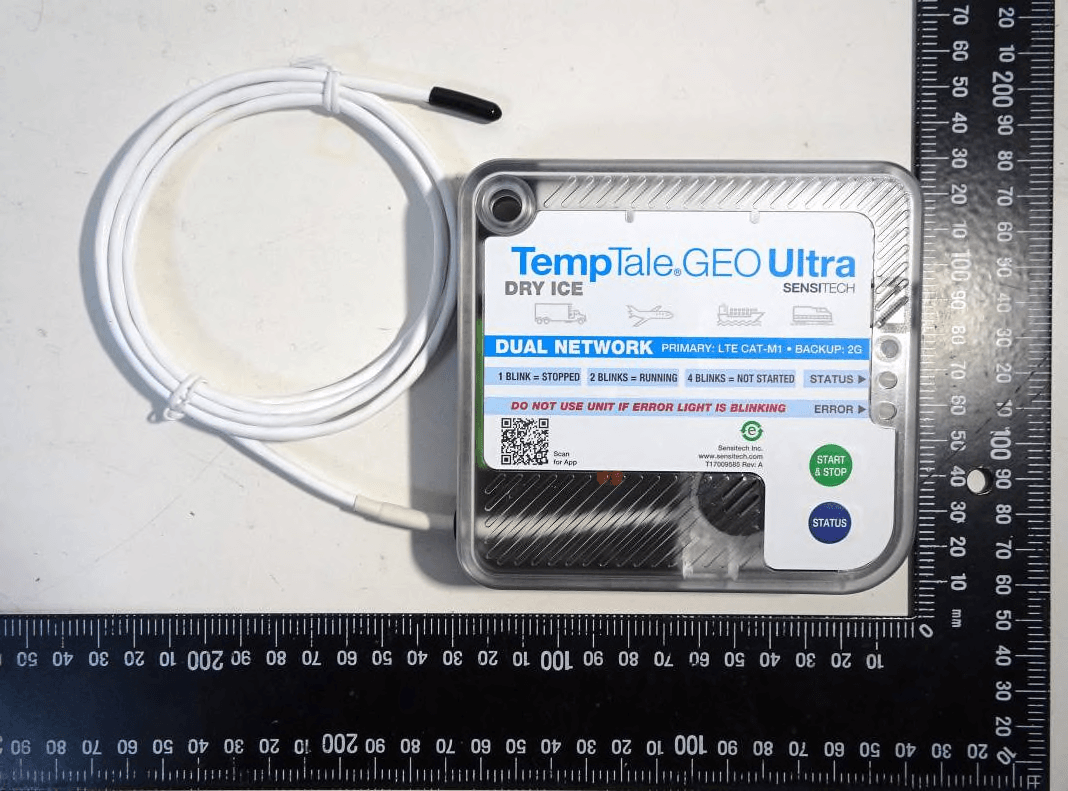
SRM-120866SST
Jan 04, 2021Temp/Humidity Data Logger / Tracker
Equipment Class
DXT - Part 15 Low Power Transceiver, Rx Verified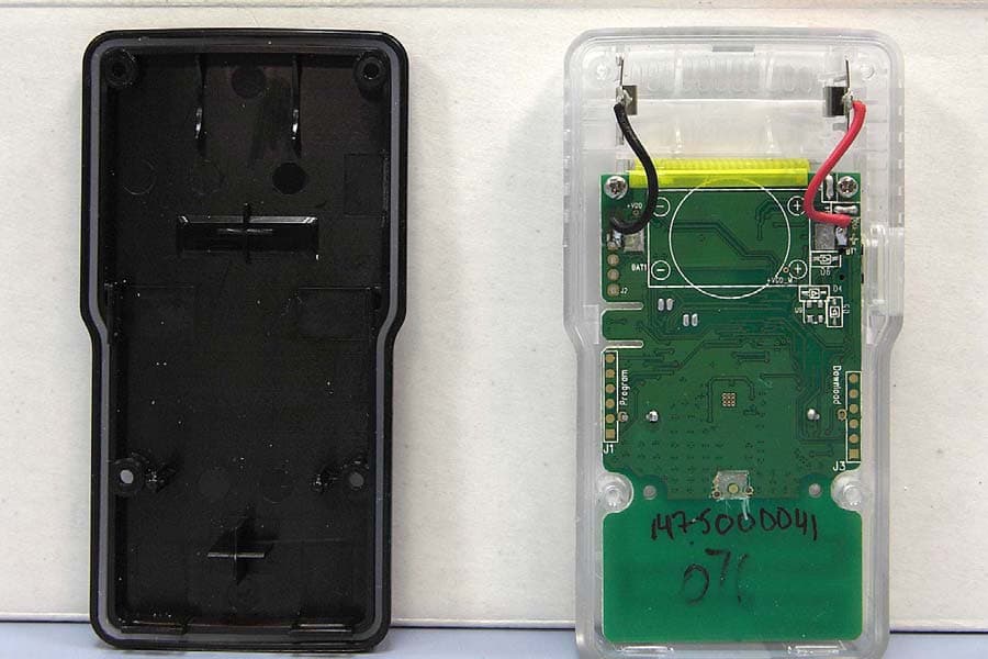
SRMT11012177
Aug 15, 2010TEMPTALE4 RF MONITOR STORES TEMPERATURE VALUES, IDENTIFIES LOCATIONS TRAVELED THROUGH AND STORES SHIPMENT INFORMATION. ALL OF THIS INFORMATION CAN BE TRANSMITTED WIRELESSLY TO A LOCAL COMPUTER.
Equipment Class
DXX - Part 15 Low Power Communication Device Transmitter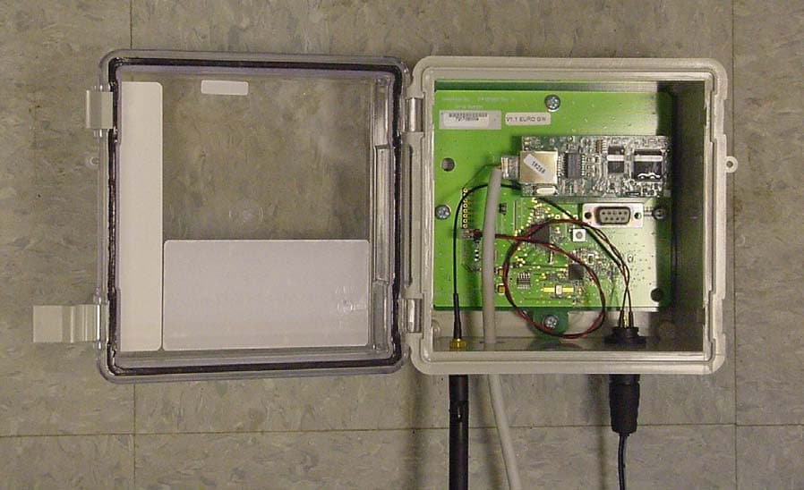
SRMT11008340
Aug 22, 2006TEMPTALE RF GATEWAY/REPEATER/SIGNPOST
Equipment Class
DXX - Part 15 Low Power Communication Device Transmitter