SRMT11012177TEMPTALE4 RF MONITOR STORES TEMPERATURE VALUES, IDENTIFIES LOCATIONS TRAVELED THROUGH AND STORES SHIPMENT INFORMATION. ALL OF THIS INFORMATION CAN BE TRANSMITTED WIRELESSLY TO A LOCAL COMPUTER.
Sensitech, INC.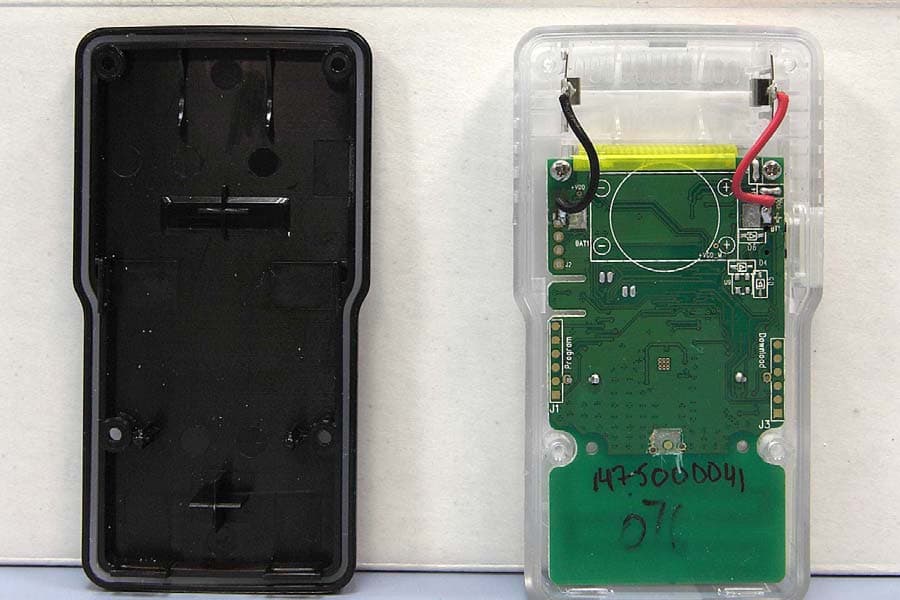
Click to zoom
Application Details
- Equipment Class
- DXX - Part 15 Low Power Communication Device Transmitter
- Date of Grant
- Aug 15, 2010
- Application Purpose
- Original Equipment
- Date of Application
- Aug 12, 2010
- Equipment Note
- TEMPTALE4 RF MONITOR STORES TEMPERATURE VALUES, IDENTIFIES LOCATIONS TRAVELED THROUGH AND STORES SHIPMENT INFORMATION. ALL OF THIS INFORMATION CAN BE TRANSMITTED WIRELESSLY TO A LOCAL COMPUTER.
- Frequency Range
- 914.90000000 - 922.27000000
- Company
- Sensitech, INC.
- Country
- United States
Documents & Files
Document Text
Text extracted from the exhibit documents filed with the FCC. Open a document above to read the original.
Users Manual
Sensitech Inc. • 800 Cummings Center • Beverly, MA 01915 (978) 927-7033 • Fax (978) 921-2112 www.sensitech.com © 2010. All Rights Reserved.TempTale is a registered trademark and TagAlert is a trademark of Sensitech, Inc.800 Cummings Center, Beverly, MA 01915 T11012177 Rev. B. TempTale ® RF Monitor Instructions For Use The Tools That Turn In formation Into Power TempTale ® Manager Software Data Management Services TempTale ® 4 Monitor TagAlert ™ Monitor Millions Depend on the Inte grity of Your Product. Sensitech’s Mission is to Ensure that Integrity. For more information, cont act our client services group at 800-843-8367. RF Monitoring TempTale ® 4 Probe Monitor FCC ID SRMT11012177 This device complies with Part 15 of the FCC Rules. Operation is subject to the following two conditions: (1) this device may not cause harmful interference, and (2)this device must accept any interference received, incl uding interference that may cause undesired operation.Changes or modifications not expressly approved by Sensitech could avoid the user’s authority to operate the equipment. AlarmaCuando el TempTale RF está fuera del límite bajo o alto del tiempo programado, un icon de alarma aparecerá a la derecha en la parte baja de la pantalla.Parar el TempTale RFPresione y libere (1 a 3 segundos) el botón de parar “Stop” hasta que el icon de “Stop” aparezca a la derecha en la parte superior de la pantalla. AlarmWhen the TempTale RF is exposed to a temperature outside a pre-programmed limit and time threshold, an “Alarm bell” will appear in the lower right corner of the LCD display. Stopping a TempTale RF MonitorPress and hold (1 to 3 seconds) the Stop button until the “Stop sign” icon appears in the upper right corner of the LCD display. Starting a TempTale RF Monitor• Press and release the Start button. • The “Sunshine” icon app ears in the upper left corner of the display. • The TempTale RF will begin to record data after the start-up delay has passed. Iniciar el TempTale RF• Presione y libere el botón de inicio “Start”. • El icon del “Sol” aparecerá a la izquierda en la parte superior de la pantalla. • El TempTale RF grabará despúes del tiempo de demura. All TempTale ® RF Monitors can be programmed with a custom Start-up delay, measurement interval and alarm settings which have been pre-determined by the customer.To mark an important event (“Date Stamp”) • TempTale RF monitors provide an option to “Date Stamp” or mark an important event at any time during the monitoring cycle that will be visible when viewing the data. The mark is displayed as an arrow when viewing the graph and shown in italics when viewing the tabular data. • To mark a graph while the monitor is r ecording, press and release the “Start” button. • The “arrow” icon will appear temporarily in the lower left corner and the temperature history will appear on the display. Data appears as follows: 1. Average temperature of Primary (Ambient) Sensor Readings2. Highest temperature recorded at Primary Sensor3. Total time above high temperature limit of Primary Sensor4. Lowest temperature recorded at Primary Sensor5. Total time below low temperature limit of Primary Sensor6. Highest RH value recorded at Secondary (RH) Sensor7. Lowest RH value recorded at Secondary (RH) Sensor Stopped recordingLimits exceeded Marked PointRecording Displayed Information Temperature data Para marcar un evento import ante (Estampa de fecha) • Los TempTale RF monitores tienen la opción de marcar un evento importante que occura durante el envio. Se puede ver esta marca cuando se baja la información. La marca aparecerá como una flecha en el grafíco y en italico en el tabular. • Para marcar el evento durante el e nvio, presione y libere el botón de inicio “Start”. • Una flecha aparecerá en la pantalla y la información de temperatura aparecerá en el siguente orden: 1. Temperatura media de las lecturas (ambiente) primarias del sensor2. La temperatura más alta registrada en el sensor primario3. Tiempo total sobre límite de alta temperatura del sensor primario4. La temperatura más baja registrada en el sensor primario5. Tiempo total debajo del límite de la baja temperatura del sensor primario6. El valor más alto de la RH registrado en el sensor secundario (RH)7. El valor más bajo de la RH registrado en el sensor secundario (RH) Pantalla del Monitor: ParadoAlarma Marca de eventoIniciado Información de temperatura Los monitores de TempTale ® RF están programado con uno tiempo de demura, intervalo y limites de temperatura y tiempo que fueron requierido por el cliente. RADIO AND TELEVISION INTERFERENCE NOTE: This equipment has been tested and f ound to comply with the limits for a Class A digital device, pursuant to Part 15 of th e FCC rules. These limits are designed to provide reasonable protection against harmful interference when the equipment is operated in a commercial envi ronment. This equipment generates, uses and can radiate radio frequency energy and, if not installed a nd used in accordance with the instruction manual, may cause harmful in terference to radio communications. Operation of this equipment in a residential area is likely to cause harmful interference in which case the user will be required to correct th e interference at his own expense.
External Photos
Sensitech – Temptale4 RF External Photos Front Rear
Internal Photos
Sensitech – Temptale4 RF Internal Photos Solder side Component Side
Test Report
Compliance Worldwide, Inc. - 357 Main Street - Sandown, NH 03873 (603) 887 3903 Fax 887 6445 http://www.complianceworldwide.com COMPLIANCE WORLDWIDE INC. TEST REPORT 269-10R1 In Accordance with the Requirements of Federal Communications Commission CFR Title 47 Part 15.249, Subpart C Industry Canada RSS 210, Issue 7 Low Power License-Exempt Radio Communication Devices Intentional Radiators Issued to Sensitech 800 Cummings Center, Suite 258X Beverly, MA 01915-6197 for the TempTale RF Monitor FCC ID: SRMT11012177 IC: 6654A-11012177 Report Issued on July 23, 2010 Tested by This test report shall not be reproduced, except in full, without written permission from Compliance Worldwide, Inc. Test Number: 269-10R1 Issue Date: 7/23/2010 Page 2 of 17 Compliance Worldwide, Inc. - 357 Main Street - Sandown, NH 03873 (603) 887 3903 Fax 887 6445 http://www.cw-inc.com Table of Contents 1. Scope .................................................................................................................................. 3 2. Product Details.................................................................................................................... 3 2.1. Manufacturer ..............................................................................................................3 2.2. Model Number............................................................................................................ 3 2.3. Serial Number ............................................................................................................ 3 2.4. Description ................................................................................................................. 3 2.5. Power Source............................................................................................................. 3 2.6. EMC Modifications ..................................................................................................... 3 3. Product Configuration ......................................................................................................... 4 3.1. Support Equipment .................................................................................................... 4 3.2. Cables ........................................................................................................................ 4 3.3. Operational Characteristics & Software ..................................................................... 4 3.4. Block Diagram ............................................................................................................ 4 4. Measurements Parameters................................................................................................. 4 4.1. Measurement Equipment Used to Perform Test ........................................................ 4 4.2. Measurement & Equipment Setup ............................................................................. 4 4.3. Measurement Procedure............................................................................................ 5 4.4. Choice of Operating Frequencies .............................................................................. 5 5. Measurement Summary...................................................................................................... 6 6. Measurement Data.............................................................................................................. 6 6.1. Antenna Requirement ................................................................................................ 7 6.2. Radiated Field Strength of Fundamental ................................................................... 7 6.3. Radiated Field Strength of Harmonics ....................................................................... 9 6.4. Band Edge Measurements....................................................................................... 10 6.5. Spurious Radiated Emissions .................................................................................. 12 6.6. Occupied Bandwidth (-26 dB) .................................................................................. 13 6.7. 99% Bandwidth ........................................................................................................ 13 6.8. Occupied (-26 dB) Bandwidth / 99% Bandwidth Plots ............................................. 13 6.9. Public Exposure to Radio Frequency Energy Levels ............................................... 15 7. Test Site Description ......................................................................................................... 17 Test Number: 269-10R1 Issue Date: 7/23/2010 Page 3 of 17 Compliance Worldwide, Inc. - 357 Main Street - Sandown, NH 03873 (603) 887 3903 Fax 887 6445 http://www.cw-inc.com 1. Scope This test report certifies that the Sensitech TempTale RF Monitor, as tested, meets the FCC Part 15, Subpart C and Industry Canada RSS 210, Issue 7 requirements. The scope of this test report is limited to the test sample provided by the client, only in as much as that sample represents other production units. If any significant changes are made to the unit, the changes shall be evaluated and a retest may be required. 2. Product Details 2.1. Manufacturer: Sensitech 2.2. Model Number: TempTale RF Monitor 2.3. Serial Number: 1475000005 2.4. Description: The TempTale RF monitor stores temperature values, identifies locations traveled through and stores shipment information. All of this information can be transmitted wirelessly to a local computer. Time and temperature information displayed on the PC also includes the location information during the trip. 2.5. Power Source: 3 Volts DC (1 CR123ASL Lithium Battery) 2.6. Hardware Revs.: Rev. A 2.7. Software Rev.: Rev. A, Version 1025 2.8. EMC Modifications: None Test Number: 269-10R1 Issue Date: 7/23/2010 Page 4 of 17 Compliance Worldwide, Inc. - 357 Main Street - Sandown, NH 03873 (603) 887 3903 Fax 887 6445 http://www.cw-inc.com Sensitech TempTale Mo…
Text truncated - open the document above for the full version.
Test Setup Photos
Test Set up photos – Temptale4 RF Radiated Front View Radiated – Rear view
Contact Information
Applicant
Eric Day
Test Firm
Compliance Worldwide, Inc.Deb Bourbeau
Technical Specifications
| # | Rule Parts | Frequency Range | Power Output | Emission |
|---|---|---|---|---|
| 1 | 15C | 914.9 MHz - 922.27 MHz | 2.00 mW | L1D |
Other Applications from Sensitech, INC.
SRMT11012920
Jul 30, 2022Sensor
Equipment Class
DSS - Part 15 Spread Spectrum TransmitterSRMT11012860
Jul 30, 2022Quarterback Gateway
Equipment Class
DTS - Digital Transmission System
SRM-120866SST
Jan 04, 2021Temp/Humidity Data Logger / Tracker
Equipment Class
DXT - Part 15 Low Power Transceiver, Rx Verified
SRMT11012294
Dec 07, 2014TempTale RF2 Datalogger, RF Temperature Monitor
Equipment Class
DXX - Part 15 Low Power Communication Device Transmitter
SRMT11008340
Aug 22, 2006TEMPTALE RF GATEWAY/REPEATER/SIGNPOST
Equipment Class
DXX - Part 15 Low Power Communication Device Transmitter