SRS-D80-EBDART Data Modem RV-D80-EB/RV-M80-EB
Raveon Technologies, Incorporated
Click to zoom
Application Details
- Equipment Class
- TNB - Licensed Non-Broadcast Station Transmitter
- Date of Grant
- Aug 23, 2015
- Application Purpose
- Original Equipment
- Date of Application
- Aug 21, 2015
- Equipment Note
- DART Data Modem RV-D80-EB/RV-M80-EB
- Frequency Range
- 896.10000000 - 901.10000000
- Country
- United States
Documents & Files
Document Text
Text extracted from the exhibit documents filed with the FCC. Open a document above to read the original.
Users Manual
1 Raveon Technologies Corp. M o d e l s : RV-D80-EB & RV-M 8 0-E B 896/9 4 0 M H z Da t a M o de m T e c h n i c a l M a n u a l Version A4 August 2015 Raveon Technologies Corporation 2320 Cousteau Ct. Vista, CA 92081 www.raveon.com 2 Raveon Technologies Corp. Table of Contents 1. General Information about the RV-D80/M80 .............................................. 4 1.1. Congratulations! ............................................................................................................................. 4 1.2. NOTICE ......................................................................................................................................... 4 1.3. Safety / Warning Information ......................................................................................................... 4 1.4. FCC Part 15 Note: ......................................................................................................................... 5 1.5. FCC Part 121.15 Statement........................................................................................................... 5 1.6. Transmitter Output Power: Warning .............................................................................................. 5 2. Overview .................................................................................................... 6 2.1. Features......................................................................................................................................... 6 2.2. Firmware Updating ........................................................................................................................ 7 2.3. General .......................................................................................................................................... 7 2.4. Transmitter Specifications (RV-D80-EB/RV-M80-EB) ................................................................... 7 2.5. Receiver Specifications ................................................................................................................. 8 2.6. Interface Specifications .................................................................................................................. 8 3. Electrical Inputs and Outputs ..................................................................... 9 3.1. RS-232/EIA232 Serial I/O Connector ............................................................................................ 9 3.2. GPS (-GX option) ......................................................................................................................... 10 4. User Serial Port Commands .................................................................... 11 4.1. Overview ...................................................................................................................................... 11 4.2. Command Mode .......................................................................................................................... 11 4.3. Setting a Parameter ..................................................................................................................... 12 4.4. Reading a Parameter ................................................................................................................... 12 4.5. CONFIG Button ........................................................................................................................... 12 4.6. Exiting the Command Mode......................................................................................................... 13 5. Command Mode Commands ................................................................... 14 5.1. General Common Commands ..................................................................................................... 14 5.2. Data Modem Mode Related Commands ...................................................................................... 16 5.3. DART Related Commands .......................................................................................................... 16 5.4. GPS Related Commands............................................................................................................. 17 5.5. Diagnostic Related Commands ................................................................................................... 17 5.6. Factory Default Settings............................................................................................................... 18 (DART Data Transceiver) .................................................................................................................... 18 6. Programming Channels and Frequencies ................................................ 18 6.1. Initializing a new RV-D80-EB/RV-M80-EB to factory defaults..................................................... 19 7. Data Transmission ................................................................................... 19 Serial Port Baud Rate .......................................................................................................................... 19 8. Debug Related Commands ...................................................................... 20 9. Diagnostic Provisions ............................................................................... 21 9.1. Overview of Diagnostics .............................................................................................................. 21 9.2. Reading the Diagnostic Information ............................................................................................. 21 9.3. Status and Statistics Command ................................................................................................... 21 10. Tune-up and Alignment ............................................................................ 22 10.1. Periodic Calibration ...................................................................................................................... 22 10.2. Calibra…
Text truncated - open the document above for the full version.
Cover Letter(s)
American Certification Body Inc. 6731 Whittier Ave, Suite C110, McLean, VA 22101, USA August 11, 2015 FCC ID SRS-D80-EB RE: ATCB017735 Thank you for your application. The following comments require your attention. Please note that further comments may arise in response to answers provided to the questions below. 1. Emissions Masks Please verify the calculation of Emissions Mask J. From Part 90.210. There should be breakpoints at 2.5kHz, 6.25 kHz and 9.5 kHz in the mask. The test report indicates breakpoints at 2.5kHz and 12.5 kHz. (j) Emission Mask J. For transmitters that are not equipped with an audio low-pass filter, the power of any emission must be attenuated below the unmodulated carrier power of the transmitter (P) as follows: (1) On any frequency removed from the center of the authorized bandwidth by a displacement frequency (f d in kHz) of more than 2.5 kHz, but no more than 6.25 kHz: At least 53 log (f d /2.5) dB; (2) On any frequency removed from the center of the authorized bandwidth by a displacement frequency (f d in kHz) of more than 6.25 kHz, but no more than 9.5 kHz: At least 103 log (f d /3.9) dB; (3) On any frequency removed from the center of the authorized bandwidth by a displacement frequency (f d in kHz) of more than 9.5 kHz: At least 157 log (f d /5.3) dB, or 50 + 10 log (P) dB or 70 dB, whichever is the lesser attenuation. Please verify that the correct masks were used for Plots 11-14. 2. EUT Photos Please provide new photos of the EUT PCB. The photos should be legible enough to view component names and PCB traces. 3. Document: Port of Long Beach Vessel Tracking System A document describing operation at 153.81 MHz was included in the application. Is this relevant to the planned operation? Is there a document that describes operation at the requested authorization (896.1-901.1 MHz)? 4. Spurious Emissions Test Data Table 5 shows the test date for spurious emissions as 08/12/09. Please check if this is correct. 5. Necessary Bandwidth l Page 2 August 11, 2015 Part 90.209 indicates an authorized bandwidth (maximum) of 13.6 kHz. Emissions designators indicate necessary bandwidths of 14kHz and 16kHz (Summary table, page 5: 16K0F1D & 14K0F1D). Please provide calculation of necessary bandwidth for these operating modes. 6. Label Label indicates compliance with “part 15, 22 and 90.” Confirm/adjust for Part 22? Label requires 15.19(a)(1) statement, which is for Part 15 devices that also are Licensed Part 90. Currently they list 15.19(a)(3) which is for all other devices under Part 15. 7. Tuneup Procedure I could not locate a tuneup procedure in the application. How is power verified and set during production? 8. Contacts The FCC listed contact and address do not match the Form 731. Though Raveon provides a letter stating the different addresses, neither match what is actually provided in the Form 731. They should correct to match the FCC database. 9. Manual The manual does not appear to have the 15.21 statement, only the 15.105 Class B statement.AC mains conducted emissions 10. DC Voltages and Currents Please provide information on the DC voltages and currents into the final RF stage. 11. User Instructions It is suggested that the User Instructions make it clear that adjusting the output power may jeopardize the licenses and authority to use the radio. Thank you, Michael Violette Application Review Engineer
External Photos
Raveon External Photos WLL 15006 1 Back View Front View Raveon External Photos WLL 15006 2 Bottom View Raveon External Photos WLL 15006 3 Top View Raveon External Photos WLL 15006 4 Left Side Right Side
ID Label/Location Info
Example of FCC Label, RV-D80-EB Example of FCC Label Text reads: FCC ID: SRS-D80-EB This device complies with parts 15 the FCC rules. Operation is subject to the following two conditions: (1) This device may not cause harmful interference. (2) This device must accept any interference received including interference that may cause undesired operation. Label Material: Silver Polyester Laminate Adhesive: 0.001 inch thick Permanent Acrylic Adhesive Location of FCC Label: RV-D80-EB Location of FCC Label: RV-M80-EB
Internal Photos
Raveon Internal Photos WLL 15006 1 PCB Digital Board – Bottom PCB Digital Board ‐ Top Raveon Internal Photos WLL 15006 2 PCB RF Board – Bottom PCB RF Board ‐ Top
RF Exposure Info
Certificates and reports shall not be reproduced except in full, without the written permission of H.B Compliance Solutions, LLC. Maximum Permissible Exposure Statement For the Raveon Technologies Corporation DART Data Modem RV-D80-EB/RV-M80-EB June 23, 2015 Prepared for: Raveon Technologies Corporation 2320 Cousteau Court, Vista, CA 92081 Prepared By: H.B. Compliance Solutions 5005 S. Ash Avenue, Suite # A-10 Tempe, Arizona 85282 Reviewed By: Hoosamuddin Bandukwala Cert # ATL-0062-E HBCS MPE Report # EMC_15006 Page 2 of 3 Prediction of MPE limit at a given distance Equation from page 18 of OET Bulletin 65, Edition 97-01 S = PG/4πR² Where, S = power density (mW/cm2) P = output power at the antenna terminal (mW) G = gain of transmit antenna (numeric) R = distance from transmitting antenna (cm) Maximum peak output power at antenna input terminal = 36.74 (dBm) Maximum peak output power at antenna input terminal = 4720 (mW) Antenna gain (typical) = 0 (dBi) Maximum antenna gain = 1.0 (numeric) Prediction distance = 36 (cm) Prediction frequency = 896.1 (MHz) MPE limit for uncontrolled exposure at prediction frequency = 0.597 (mW/cm^2) Power density at prediction frequency = 0.2898277 (mW/cm^2) To solve for the minimum mounting distance required; R = √ (PG/4πS) R = √ (4720 x 1.0 / 4π x 0.2898277) = 36 cm (Based on continuous transmission) HBCS MPE Report # EMC_15006 Page 3 of 3 Maximum peak output power at antenna input terminal = 36.74 (dBm) Maximum peak output power at antenna input terminal = 4720 (mW) Antenna gain (typical) = 6 (dBi) Maximum antenna gain = 3.98 (numeric) Prediction distance = 100 (cm) Prediction frequency = 896.1 (MHz) MPE limit for uncontrolled exposure at prediction frequency = 0.597 (mW/cm^2) Power density at prediction frequency = 0.1494954 (mW/cm^2) To solve for the minimum mounting distance required; R = √ (PG/4πS) R = √ (4720 x 3.98 / 4π x 0.1494954) = 100 cm (Based on continuous transmission) END OF TEST REPORT
Test Report
Certificates and reports shall not be reproduced except in full, without the written permission of H.B Compliance Solutions, LLC. Intentional Radiator Test Report For the Raveon Technologies Corporation DART Data Modem RV-D80-EB/RV-M80-EB Tested under The FCC Rules contained in Title 47 of the CFR, Part 90 for Private Land Mobile Radio Services June 22, 2015 Prepared for: Raveon Technologies, Corp 2320 Cousteau Court Vista, CA 92081 Prepared By: H.B. Compliance Solutions 5005 S. Ash Avenue, Suite A-10 Tempe, Arizona 85282 Reviewed By: Hoosamuddin Bandukwala Cert # ATL-0062-E Engineering Statement: The measurements shown in this report were made in accordance with the procedure indicated, and the emissions from this equipment were found to be within the limits applicable. I assume full responsibility for the accuracy and completeness of these measurements, and for the qualifications of all persons taking them. It is further stated that upon the basis of the measurement made, the equipment tested is capable of operation in accordance with the requirements of Part 90 of the FCC Rules under normal use and maintenance. HBCS Report # EMC_15006 Rev1 Page 2 of 29 Report Status Sheet Revision # Report Date Reason for Revision Ø June 22, 2015 Initial Issue 1 August 11, 2015 Updated Mask J and Necessary BW 2 August 21, 2015 Removed 14K and 16K Necessary BW HBCS Report # EMC_15006 Rev1 Page 3 of 29 Table of Contents EXECUTIVE SUMMARY ............................................................................................ 4 1. Testing Summary ........................................................................................ 4 EQUIPMENT CONFIGURATION ................................................................................ 5 1. Overview .................................................................................................... 5 2. Test Facility ................................................................................................. 6 3. Description of Test Sample ......................................................................... 6 4. Equipment Configuration ........................................................................... 6 5. Support Equipment .................................................................................... 6 6. Ports and Cabling Information .................................................................... 6 7. Method of Monitoring EUT Operation ........................................................ 7 8. Mode of Operation ..................................................................................... 7 9. Modifications ............................................................................................. 7 10. Disposition of EUT ...................................................................................... 7 Criteria for Intentional Radiators ............................................................................ 8 1. RF Power Output ........................................................................................ 8 2. Modulation Characteristics ....................................................................... 12 3. Occupied Bandwidth (Emission Mask) ...................................................... 14 4. Spurious Emissions at Antenna Terminals ................................................ 18 5. Radiated Spurious Emissions .................................................................... 22 6. Frequency Stability vs Temperature ......................................................... 24 7. Frequency Stability vs Voltage .................................................................. 26 8. Necessary Bandwidth ............................................................................... 28 I. Test Equipment .............................................................................................. 29 HBCS Report # EMC_15006 Rev1 Page 4 of 29 EXECUTIVE SUMMARY 1. Testing Summary These tests were conducted on a sample of the equipment for the purpose of demonstrating compliance with Part 90. All tests were conducted using measurement procedure from ANSI TIA/EIA-603-D-2010 as appropriate. Test Name Test Method/Standard Result Comments RF Output Power 2.1046; 90.205 Pass Modulation Characteristics 2.1047(a) Pass The EUT does not transmit voice. The device transmit data signal only Occupied Bandwidth 2.1049; 90.210 Pass EUT Meets Mask J Spurious Emissions at Antenna Terminals 2.1051; 90.210 Pass Radiated Spurious Emissions 2.1053; 90.210 Pass Frequency Stability over Temperature Variations 2.1055(a)(1); 90.213 Pass Frequency Stability over Voltage Variations 2.1055(d) Pass Transient Frequency Behavior 90.214 N/A Device does not operate in 150- 174 or 421-512MHz Band HBCS Report # EMC_15006 Rev1 Page 5 of 29 EQUIPMENT CONFIGURATION 1. Overview H.B Compliance Solutions was contracted by Raveon Technologies Corporation to perform testing on the RV-D80-EB/RV-M80-EB UHF Data Modem under the purchase order number 6402. This document describes the test setups, test methods, required test equipment, and the test limit criteria used to perform compliance testing of the Raveon Technologies Corporation, RV- D80-EB/RV-M80-EB UHM Data Modem. The tests were based on FCC Part 90 Rules. The tests described in this document were formal tests as described with the objective of the testing was to evaluate compliance of the Equipment Under Test (EUT) to the requirements of the aforementioned specifications. Raveon Technologies Corporation should retain a copy of this document and it should be kept on file for at least five years after the manufacturing of the EUT has been permanently discontinued. The results obtained relate only to the item(s) tested. Product Name: DART Radio Modem Model(s) Tested: RV-D80-EB/RV-M80-EB FCC ID: SRS-D80-EB Supply Voltage Input: Primary Power : 12 Vdc Frequency Range: 896.1MHz to 901.1MHz No. of Channels: Single Chanel Necessary Bandwidth 12.5 & 25kHz Type(s) of…
Text truncated - open the document above for the full version.
Test Setup Photos
1 | Page HBCS 15006 Raveon Technologies Test Setup Photos Test Setup Photo # 1 Test Setup Photo # 2 2 | Page HBCS 15006 Test Setup Photo # 3 Test Setup Photo # 4 3 | Page HBCS 15006 Test Setup Photo # 5 Test Setup Photo # 6
Contact Information
Applicant
John Richard Sonnenberg(CEO)
Test Firm
SMART EC Product Testing ServicesTeresa Kaczmarowski
[email protected]602 437 6898
Technical Specifications
| # | Rule Parts | Frequency Range | Power Output | Emission | Tolerance |
|---|---|---|---|---|---|
| 2 | 9 | 896.1 MHz - 901.1 MHz | 4.72 W | 11K0F1D | 0.1 ppm |
Other Applications from Raveon Technologies, Incorporated

SRS-PT-VB
Mar 18, 2014VHF Band 0.5-5 Watt Data Radio
Equipment Class
TNB - Licensed Non-Broadcast Station Transmitter
SRS-M7-VM
Mar 25, 2010VHF Wireless Data Modem
Equipment Class
TNB - Licensed Non-Broadcast Station Transmitter
SRS-M7-VB
Mar 25, 2010VHF Wireless Data Modem
Equipment Class
TNB - Licensed Non-Broadcast Station Transmitter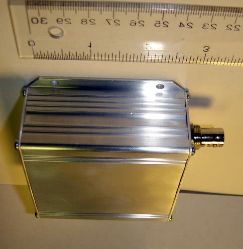
SRS-RV-M5-VB-N2
May 02, 2007RF Data Modem
Equipment Class
TNB - Licensed Non-Broadcast Station Transmitter
SRS-RV-M5-UC
Dec 28, 2005RF Data Modem
Equipment Class
TNB - Licensed Non-Broadcast Station Transmitter