SRX-FULLW001WLAN Module
INTELLIGENT SYSTEMS Co.,Ltd.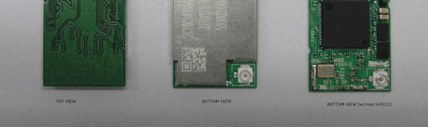
Click to zoom
Application Details
- Equipment Class
- DTS - Digital Transmission System
- Date of Grant
- Feb 04, 2015
- Application Purpose
- Original Equipment
- Date of Application
- Feb 04, 2015
- Equipment Note
- WLAN Module
- Frequency Range
- 2412.00000000 - 2472.00000000
- Company
- INTELLIGENT SYSTEMS Co.,Ltd.
- Country
- Japan
Documents & Files
Document Text
Text extracted from the exhibit documents filed with the FCC. Open a document above to read the original.
Users Manual
FULLW001 User manual The “J27H023.01 WLAN MODULE” made by HON HAI Precision Ind. Co., Ltd. is embedded. 2015 INTELLIGENT SYSTEMS CO.,LTD. Released: January 30 2015 2 Introduction The J27H023.01 802.11b/g module provides wireless modem functionality utilizing direct sequence spread spectrum and OFDM/CCK technology. 1.1 WLAN Features Operating Frequency 2412 ~ 2483.5 MHz ISM band Modulation Schemes 802.11b (DSSS): DBPSK, DQPSK, CCK 802.11g (OFDM): BPSK, QPSK, 16QAM, 64QAM Channel Numbers IEEE 802.11 g compliant: 1 ~ 11 channels for United States 1 ~ 13 channels for Europe, Japan IEEE 802.11 b compliant: 1 ~ 13 channels for United States, Europe and Japan WLAN Data Rate 802.11g: Up to 54 Mbps with auto fallback to 48, 36, 24, 18, 12, 9 and 6 Mbps. 802.11b: Up to 11 Mbps with auto fallback to 5.5, 2 and 1Mbps. Media Access Protocol CSMA/CA with ACK Output Power 8.02.11g: 15.06dBm ( C o n d u c t e d ) 8.02.11b: 9.18dBm ( C o n d u c t e d ) Antenna Type Single antenna connector for off board antenna Operating Voltage 1.8 VDC and 3.3 VDC Operating Systems Windows 98/Me/2000/XP 3 1.2 FCC Notice Federal Communication Commission Interference Statement This equipment has been tested and found to comply with the limits for a Class B digital device, pursuant to Part 15 of the FCC Rules. These limits are designed to provide reasonable protection against harmful interference in a residential installation. This equipment generates uses and can radiate radio frequency energy and, if not installed and used in accordance with the instructions, may cause harmful interference to radio communications. However, there is no guarantee that interference will not occur in a particular installation. If this equipment does cause harmful interference to radio or television reception, which can be determined by turning the equipment off and on, the user is encouraged to try to correct the interference by one of the following measures: - Reorient or relocate the receiving antenna. - Increase the separation between the equipment and receiver. - Connect the equipment into an outlet on a circuit different from that to which the receiver is connected. - Consult the dealer or an experienced radio/TV technician for help. This device complies with Part 15 of the FCC Rules. Operation is subject to the following two conditions: (1) This device may not cause harmful interference, and (2) this device must accept any interference received, including interference that may cause undesired operation. FCC Caution: Any changes or modifications not expressly approved by the party responsible for compliance could void the user's authority to operate this equipment. 4 IMPORTANT NOTE: FCC Radiation Exposure Statement: This equipment complies with FCC radiation exposure limits set forth for an uncontrolled environment. This transmitter must not be co-located or operating in conjunction with any other antenna or transmitter. FOXCONN declared that J27H023.01 is limited in CH1~11 from 2412 to 2462 MHz (8 02. 11 g ) by specified firmware controlled in USA. This device is intended only for OEM integrators under the following conditions: The antenna must be installed such that 20 cm is maintained between the antenna and users, and The transmitter module may not be co-located with any other transmitter or antenna. As long as 2 conditions above are met, further transmitter test will not be required. However, the OEM integrator is still responsible for testing their end-product for any additional compliance requirements required with this module installed (for example, digital device emissions, PC peripheral requirements, etc.). IMPORTANT NOTE: In the event that these conditions can not be met (for example certain laptop configurations or co-location with another transmitter), then the FCC authorization is no longer considered valid and the FCC ID can not be used on the final product. In these circumstances, the OEM integrator will be responsible for re-evaluating the end product (including the transmitter) and obtaining a separate FCC authorization. End Product Labelling This transmitter module is authorized only for use in device where the antenna may be installed such that 20 cm may be maintained between the antenna and users. The final end product must be labelled in a visible area with the following: “Contains FCC ID: SRX-FULLW001”. Manual Information That Must be Included The OEM integrator has to be aware not to provide information to the end user regarding how to install or remove this RF module in the user manual of the end product which integrates this module. The users manual for OEM integrators must include the following information in a prominent location “IMPORTANT NOTE: To comply with FCC RF exposure compliance requirements, the antenna used for this transmitter must be installed to provide a separation distance of at least 20 cm from all persons and must not be co-located or operating in conjunction with any other antenna or transmitter. 1.3 Canada Notice Industry Canada Statement This radio transmitter (IC: 5567A–FULLW001) has been approved by Industry Canada to operate with the antenna types listed below with the maximum permissible gain indicated. Antenna types not included in this list, having a gain greater than the maximum gain indicated for that type, are strictly prohibited for use with this device. Antenna type: 1/2 lambda type Gain: 2.14 dBi Impedance: 50 ohms Le présent émetteur radio (IC: 5567A–FULLW001) a été approuvé par Industrie Canada pour fonctionner avec les types d'antenne énumérés ci-dessous et ayant un gain admissible maximal. Les types d'antenne non inclus dans cette liste, et dont le gain est supérieur au gain maximal indiqué, sont strictement interdits pour 5 l'exploitation de l'émetteur. Type d'antenne: Type 1/2 lambda Gain: 2.14 dBi Impédance: 50 ohms). This device complies with Industry Canada’s licence-exempt RSSs. Operation is subject to the following two conditions: (1) This device may not cause int…
Text truncated - open the document above for the full version.
External Photos
2015 INTELLIGENT SYSTEMS CO.,LTD. CONFIDENTIAL Released: January 30 2015 FULLW001 Outline Drawing Photos The “J27H023.01 WLAN MODULE” made by HON HAI Precision Ind. Co., Ltd. is embedded.
ID Label/Location Info
February 4, 2015 INTELLIGENT SYSTEMS CO.,LTD. Label Format Location Module Top Face
Internal Photos
2015 INTELLIGENT SYSTEMS CO.,LTD. CONFIDENTIAL Released: January 30 2015 FULLW001 Outline Drawing Photos The “J27H023.01 WLAN MODULE” made by HON HAI Precision Ind. Co., Ltd. is embedded.
RF Exposure Info
FCC ID: SRX-FULLW001 IC: 5567A-FULLW001 Produkte Products RF Exposure Statement: 50020244 001 Page 1 of 1 Client: INTELLIGENT SYSTEMS CO. LTD. 60 Kamitakamatsu-cho, Fukuine Higashiyama-ku, Kyoto city, Kyoto Pre., 605-0983 Japan Test item: WLAN Module Identification: FULLW001 FCC Requirement According to FCC 2.1091, mobile equipment must comply with the following applicable limit for maximum permissible exposure (MPE) specified in FCC 1.1310: Equipment Use Frequency Range Power Density [mW/cm 2 ] Average Time [min] General Population / Uncontrolled Exposure 1.5 – 100GHz 1 30 IC Requirement According to RSS-102 (Issue 4), clause 2.5.2, no routine RF exposure evaluation is required if the transmitter has a minimum separation distance to the user greater than 20cm and has an output power (e.i.r.p.) below the following threshold: Frequency Range RF Exp. Evaluation Threshold [W] Above 1.5GHz 5 Measurement Result The maximum measured transmitter power is given in the following table: Conducted Output Power P out [mW] Maximum Antenna Gain [dBi] EIRP Output Powe r [mW] Power Density at 20cm [mW/cm 2 ] 32.1 2.62 58.682 0.01167 Note: The power density S in mW/cm 2 is calculated according to the Friis formula: S = (P out · G) / (4π · D 2 ), where P out = antenna conducted output power in mW, G = antenna gain in linear scale (here: 2.62dBi = 1.828 linear), D = distance between observation point and radiating structure in cm (here: 20cm). Conclusion The device complies with the FCC and IC RF exposure requirements since the maximum transmitter power density is below the FCC limit and the e.i.r.p. output power is below the IC RF exposure evaluation exemption threshold. TÜV Rheinland Japan Ltd. – Global Technology Assessment Center 4-25-2 Kita-Yamata, Tsuzuki-ku, Yokohama 224-0021, Japan
Test Report
NVLAP LAB CODE: 200572-0 This laboratory is accredited by the NVLAP LAB CODE 200572-0, U.S.A. The tests reported herein have been performed in accordance with its terms of accreditation. *As for the range of Accreditation in NVLAP, you may refer to the WEB address, http://www.ul.com/japan/jpn/pages/services/emc/abo ut/mark1/index.jsp#nvlap FCC CFR47 PART 15 SUBPART C INDUSTRY CANADA RSS-210 ISSUE 8 CERTIFICATION TEST REPORT FOR WLAN Module MODEL NUMBER: J27H023.01 FCC ID: MCLJ27H02301 IC: 2878D-J27H02301 REPORT NUMBER: 32FE0108-HO-01-A-R1 ISSUE DATE: June 27, 2012 Prepared for HON HAI Precision Ind. Co., Ltd. 5F-1, 5, Hsin-An Road Hsinchu Science-Based Industrial Park, Taiwan Prepared by UL Japan, Inc. Head Office EMC Lab. 4383-326 Asama-cho, Ise-shi, Mie-ken 516-0021 JAPAN TEL: +81 596 24 8116 FAX: +81 596 24 8124 REPORT NO: 32FE0108-HO-01-A-R1 DATE: June 27, 2012 FCC ID: MCLJ27H02301 IC: 2878D-J27H02301 Page 2 of 82 UL Japan, Inc. Head Office EMC Lab. 4383-326 Asama-cho, Ise-shi, Mie-ken 516-0021 JAPAN TEL: +81 596 24 8116 FAX: +81 596 24 8124 This report shall not be reproduced except in full, without the written approval of UL Japan, Inc. Revision History Rev. Issue Date Revisions Revised By -- 02/16/12 Initial Issue M.Nishiyama 1 06/27/12 Addition of the test equipment (MHA-16) *This report is a revised version of 32FE0108-HO- 01-A, which is replaced with this report. M.Nishiyama REPORT NO: 32FE0108-HO-01-A-R1 DATE: June 27, 2012 FCC ID: MCLJ27H02301 IC: 2878D-J27H02301 Page 3 of 82 UL Japan, Inc. Head Office EMC Lab. 4383-326 Asama-cho, Ise-shi, Mie-ken 516-0021 JAPAN TEL: +81 596 24 8116 FAX: +81 596 24 8124 This report shall not be reproduced except in full, without the written approval of UL Japan, Inc. TABLE OF CONTENTS 1. ATTESTATION OF TEST RESULTS ................................................................................. 5 2. TEST METHODOLOGY ..................................................................................................... 6 3. FACILITIES AND ACCREDITATION ................................................................................. 6 4. CALIBRATION AND UNCERTAINTY ................................................................................ 6 4.1. MEASURING INSTRUMENT CALIBRATION ............................................................... 6 4.2. SAMPLE CALCULATION ............................................................................................. 6 4.3. MEASUREMENT UNCERTAINTY................................................................................ 7 5. EQUIPMENT UNDER TEST ............................................................................................... 8 5.1. DESCRIPTION OF EUT ............................................................................................... 8 5.2. MAXIMUM OUTPUT POWER ...................................................................................... 8 5.3 SOFTWARE AND FIRMWARE .................................................................................... 8 5.4 WORST-CASE CONFIGURATIONS ............................................................................ 9 5.5 DESCRIPTION OF TEST SETUP ...............................................................................10 6 ANTENNA PORT TEST RESULTS ...................................................................................16 6.1 802.11b MODE IN THE 2.4 GHz BAND ......................................................................16 6.1.1 6 dB BANDWIDTH ................................................................................................16 6.1.2 99% BANDWIDTH ................................................................................................19 6.1.3 OUTPUT POWER ................................................................................................22 6.1.4 AVERAGE POWER ..............................................................................................23 6.1.5 POWER SPECTRAL DENSITY ............................................................................24 6.1.6 CONDUCTED SPURIOUS EMISSIONS ...............................................................27 6.2 802.11g MODE IN THE 2.4 GHz BAND ......................................................................31 6.2.1 6 dB BANDWIDTH ................................................................................................31 6.2.2 99% BANDWIDTH ................................................................................................34 6.2.3 OUTPUT POWER ................................................................................................37 6.2.4 AVERAGE POWER ..............................................................................................38 6.2.5 POWER SPECTRAL DENSITY ............................................................................39 6.2.6 CONDUCTED SPURIOUS EMISSIONS ...............................................................42 7 RADIATED TEST RESULTS .............................................................................................46 7.1 LIMITS AND PROCEDURE .........................................................................................46 7.2 TRANSMITTER ABOVE 1 GHz ...................................................................................47 7.2.1 TX ABOVE 1 GHz FOR 802.11b MODE IN THE 2.4 GHz BAND ..........................47 7.2.2 TX ABOVE 1 GHz FOR 802.11g MODE IN THE 2.4 GHz BAND ..........................53 7.3 RECEIVER ABOVE 1 GHz ..........................................................................................59 7.3.1 RX ABOVE 1 GHz FOR 20 MHz BANDWIDTH IN THE 2.4 GHz BAND ...............59 7.4 WORST-CASE RADIATED EMISSIONS BELOW 1 GHz ............................................60 8 AC POWER LINE CONDUCTED EMISSIONS ..................................................................68 REPORT NO: 32FE0108-HO-01-A-R1 DATE: June 27, 2012 FCC ID: MCLJ27H02301 IC: 2878D-J27H02301 Page 4 of 82 UL Japan, Inc. He…
Text truncated - open the document above for the full version.
Test Report
A-007-14-C (FCC ID: SRX-FULLW001) Page 2 of 38 Report Version: A KEC Testing Division Table of Contents 0. REVISION HISTORY ........................................................................................................................................ 3 1. LABORATORY INFORMATION ..................................................................................................................... 4 1.1. Laboratory Accreditation .............................................................................................................................. 4 1.2. Test Facility .................................................................................................................................................. 4 1.3. Measurement Uncertainty ............................................................................................................................. 4 2. GENERAL INFORMATION ............................................................................................................................. 5 2.1. Product Description ...................................................................................................................................... 5 3. TESTED SYSTEM .............................................................................................................................................. 6 3.1. Reference Rule and Specification ................................................................................................................. 6 3.2. Date of Test ................................................................................................................................................... 6 3.3. Deviation of Standard ................................................................................................................................... 6 3.4. Test Mode ..................................................................................................................................................... 6 3.5. Block Diagram of TEST System .................................................................................................................. 7 3.6. List of Test System ....................................................................................................................................... 8 3.7. List of Cables ................................................................................................................................................ 8 4. AC POWER LINE CONDUCTED EMISSION MEASUREMENT .............................................................. 9 4.1. Test Procedure .............................................................................................................................................. 9 4.2. Test Software List ......................................................................................................................................... 9 4.3. Test Results ................................................................................................................................................. 10 5. PEAK CONDUCTED OUTPUT POWER MEASUREMENT ..................................................................... 17 5.1. Test Procedure ............................................................................................................................................ 17 5.2. Test Results ................................................................................................................................................. 17 6. Spurious Emission (The Frequency Range of 9kHz to 30MHz) .................................................................... 18 6.1. Test Procedure ............................................................................................................................................ 18 6.2. Test Results ................................................................................................................................................. 19 7. Spurious Emission (The Frequency Range of above 30MHz) ....................................................................... 20 7.1. Test Procedure ............................................................................................................................................ 20 7.2. Test Software List ....................................................................................................................................... 20 7.3. Test Results ................................................................................................................................................. 21 8. TEST EQUIPMENT ......................................................................................................................................... 36 APPENDIX A (DECLARATION OF COMPLIANCE TO MAXIMUM PERMISSIBLE EXPOSURE LIMITS FOR HUMANS) ...................................................................................................................................... 38 A-007-14-C (FCC ID: SRX-FULLW001) Page 3 of 38 Report Version: A KEC Testing Division 0. REVISION HISTORY Report Version Page Description Date of Issue A - Initial issue of report 29 January 2015 A-007-14-C (FCC ID: SRX-FULLW001) Page 4 of 38 Report Version: A KEC Testing Division 1. LABORATORY INFORMATION 1.1. Laboratory Accreditation The KEC has been accredited by the following organizations based on their criteria for testing laboratory (ISO/IEC 17025). (1) Japan Accreditation Board for Conformity Assessment (JAB) : Accreditation Number: RTL02810 (2) Voluntary EMC Laboratory Accreditation Center Inc. (VLAC) : Accreditation Number: VLAC-005 1.2. Test Facility All tests described in this report were performed by: Name: KEC Electronic Industry Development Center Testing Division Address: 3-2-2, Hikari-dai, Seika-cho, Soraku-gun, Kyoto 619-0237 Japan Anechoic Chamber : No.1 No.2 No.3 No.6 No.7 No.8 No.9 No.10 No.11 No.12 Shielded Room : No.1 No.7 No.8 No.9…
Text truncated - open the document above for the full version.
Test Report
A-008-14-C (FCC ID: SRX-FULLW001) Page 2 of 38 Report Version: A KEC Testing Division Table of Contents 0. REVISION HISTORY ........................................................................................................................................ 3 1. LABORATORY INFORMATION ..................................................................................................................... 4 1.1. Laboratory Accreditation .............................................................................................................................. 4 1.2. Test Facility .................................................................................................................................................. 4 1.3. Measurement Uncertainty ............................................................................................................................. 4 2. GENERAL INFORMATION ............................................................................................................................. 5 2.1. Product Description ...................................................................................................................................... 5 3. TESTED SYSTEM .............................................................................................................................................. 6 3.1. Reference Rule and Specification ................................................................................................................. 6 3.2. Date of Test ................................................................................................................................................... 6 3.3. Deviation of Standard ................................................................................................................................... 6 3.4. Test Mode ..................................................................................................................................................... 6 3.5. Block Diagram of TEST System .................................................................................................................. 7 3.6. List of Test System ....................................................................................................................................... 8 3.7. List of Cables ................................................................................................................................................ 8 4. AC POWER LINE CONDUCTED EMISSION MEASUREMENT .............................................................. 9 4.1. Test Procedure .............................................................................................................................................. 9 4.2. Test Software List ......................................................................................................................................... 9 4.3. Test Results ................................................................................................................................................. 10 5. PEAK CONDUCTED OUTPUT POWER MEASUREMENT ..................................................................... 17 5.1. Test Procedure ............................................................................................................................................ 17 5.2. Test Results ................................................................................................................................................. 17 6. Spurious Emission (The Frequency Range of 9kHz to 30MHz) .................................................................... 18 6.1. Test Procedure ............................................................................................................................................ 18 6.2. Test Results ................................................................................................................................................. 19 7. Spurious Emission (The Frequency Range of above 30MHz) ....................................................................... 20 7.1. Test Procedure ............................................................................................................................................ 20 7.2. Test Software List ....................................................................................................................................... 20 7.3. Test Results ................................................................................................................................................. 21 8. TEST EQUIPMENT ......................................................................................................................................... 36 APPENDIX A (DECLARATION OF COMPLIANCE TO MAXIMUM PERMISSIBLE EXPOSURE LIMITS FOR HUMANS) ...................................................................................................................................... 38 A-008-14-C (FCC ID: SRX-FULLW001) Page 3 of 38 Report Version: A KEC Testing Division 0. REVISION HISTORY Report Version Page Description Date of Issue A - Initial issue of report 29 January 2015 A-008-14-C (FCC ID: SRX-FULLW001) Page 4 of 38 Report Version: A KEC Testing Division 1. LABORATORY INFORMATION 1.1. Laboratory Accreditation The KEC has been accredited by the following organizations based on their criteria for testing laboratory (ISO/IEC 17025). (1) Japan Accreditation Board for Conformity Assessment (JAB) : Accreditation Number: RTL02810 (2) Voluntary EMC Laboratory Accreditation Center Inc. (VLAC) : Accreditation Number: VLAC-005 1.2. Test Facility All tests described in this report were performed by: Name: KEC Electronic Industry Development Center Testing Division Address: 3-2-2, Hikari-dai, Seika-cho, Soraku-gun, Kyoto 619-0237 Japan Anechoic Chamber : No.1 No.2 No.3 No.6 No.7 No.8 No.9 No.10 No.11 No.12 Shielded Room : No.1 No.7 No.8 No.9…
Text truncated - open the document above for the full version.
Test Setup Photos
REPORT NO: 32FE0108-HO-01-A-R1 DATE: June 27, 2012 FCC ID: MCLJ27H02301 IC: 2878D-J27H02301 Page 76 of 82 UL Japan, Inc. Head Office EMC Lab. 4383-326 Asama-cho, Ise-shi, Mie-ken 516-0021 JAPAN TEL: +81 596 24 8116 FAX: +81 596 24 8124 This report shall not be reproduced except in full, without the written approval of UL Japan, Inc. 10 SETUP PHOTOS RADIATED RF MEASUREMENT SETUP FOR PORTABLE CONFIGURATION X-AXIS FRONT PHOTO X-AXIS BACK PHOTO REPORT NO: 32FE0108-HO-01-A-R1 DATE: June 27, 2012 FCC ID: MCLJ27H02301 IC: 2878D-J27H02301 Page 77 of 82 UL Japan, Inc. Head Office EMC Lab. 4383-326 Asama-cho, Ise-shi, Mie-ken 516-0021 JAPAN TEL: +81 596 24 8116 FAX: +81 596 24 8124 This report shall not be reproduced except in full, without the written approval of UL Japan, Inc. Y-AXIS FRONT PHOTO Y-AXIS BACK PHOTO REPORT NO: 32FE0108-HO-01-A-R1 DATE: June 27, 2012 FCC ID: MCLJ27H02301 IC: 2878D-J27H02301 Page 78 of 82 UL Japan, Inc. Head Office EMC Lab. 4383-326 Asama-cho, Ise-shi, Mie-ken 516-0021 JAPAN TEL: +81 596 24 8116 FAX: +81 596 24 8124 This report shall not be reproduced except in full, without the written approval of UL Japan, Inc. Z-AXIS FRONT PHOTO Z-AXIS BACK PHOTO REPORT NO: 32FE0108-HO-01-A-R1 DATE: June 27, 2012 FCC ID: MCLJ27H02301 IC: 2878D-J27H02301 Page 79 of 82 UL Japan, Inc. Head Office EMC Lab. 4383-326 Asama-cho, Ise-shi, Mie-ken 516-0021 JAPAN TEL: +81 596 24 8116 FAX: +81 596 24 8124 This report shall not be reproduced except in full, without the written approval of UL Japan, Inc. RADIATED RF MEASUREMENT SETUP FOR PORTABLE CONFIGURATION (Addition of Host device) Z-AXIS FRONT PHOTO Z-AXIS BACK PHOTO REPORT NO: 32FE0108-HO-01-A-R1 DATE: June 27, 2012 FCC ID: MCLJ27H02301 IC: 2878D-J27H02301 Page 80 of 82 UL Japan, Inc. Head Office EMC Lab. 4383-326 Asama-cho, Ise-shi, Mie-ken 516-0021 JAPAN TEL: +81 596 24 8116 FAX: +81 596 24 8124 This report shall not be reproduced except in full, without the written approval of UL Japan, Inc. POWERLINE CONDUCTED EMISSIONS MEASUREMENT SETUP LINE CONDUCTED FRONT PHOTO LINE CONDUCTED BACK PHOTO REPORT NO: 32FE0108-HO-01-A-R1 DATE: June 27, 2012 FCC ID: MCLJ27H02301 IC: 2878D-J27H02301 Page 81 of 82 UL Japan, Inc. Head Office EMC Lab. 4383-326 Asama-cho, Ise-shi, Mie-ken 516-0021 JAPAN TEL: +81 596 24 8116 FAX: +81 596 24 8124 This report shall not be reproduced except in full, without the written approval of UL Japan, Inc. POWERLINE CONDUCTED EMISSIONS MEASUREMENT SETUP (Addition of Host device) LINE CONDUCTED FRONT PHOTO LINE CONDUCTED BACK PHOTO REPORT NO: 32FE0108-HO-01-A-R1 DATE: June 27, 2012 FCC ID: MCLJ27H02301 IC: 2878D-J27H02301 Page 82 of 82 UL Japan, Inc. Head Office EMC Lab. 4383-326 Asama-cho, Ise-shi, Mie-ken 516-0021 JAPAN TEL: +81 596 24 8116 FAX: +81 596 24 8124 This report shall not be reproduced except in full, without the written approval of UL Japan, Inc. END OF REPORT
Test Setup Photos
A-007-14-C (FCC ID: SRX-FULLW001) Page 1 of 2 KEC Testing Division 1. APPENDIX Photographs of EUT System Configuration AC Power Line Conducted Emission Measurement A-007-14-C (FCC ID: SRX-FULLW001) Page 2 of 2 KEC Testing Division Spurious Emissions Measurement (Radiated) Above 1GHz
Test Setup Photos
A-008-14-C (FCC ID: SRX-FULLW001) Page 1 of 2 KEC Testing Division 1. APPENDIX Photographs of EUT System Configuration AC Power Line Conducted Emission Measurement A-008-14-C (FCC ID: SRX-FULLW001) Page 2 of 2 KEC Testing Division Spurious Emissions Measurement (Radiated) Above 1GHz
Contact Information
Applicant
Takeshi Narita
Technical Contact
TUV Rheinland Japan Ltd.Miyuki Tamura
[email protected]+81459143888
4-25-2 Kita-Yamata · Yokohama · Japan
Test Firm
KEC Electronic Industry Development CenterSeiichi Izumi
Technical Specifications
| # | Rule Parts | Frequency Range | Power Output |
|---|---|---|---|
| 2 | 15C | 2.41 GHz - 2.47 GHz | 8.30 mW |
Other Applications from INTELLIGENT SYSTEMS Co.,Ltd.
SRX-SZK001
Feb 04, 2015IS-SNAKE-BOX
Equipment Class
DXX - Part 15 Low Power Communication Device Transmitter
SRX-ISJRLMC
Sep 05, 2011Game Development Tool
Equipment Class
DTS - Digital Transmission System