SRX-SZK001IS-SNAKE-BOX
INTELLIGENT SYSTEMS Co.,Ltd.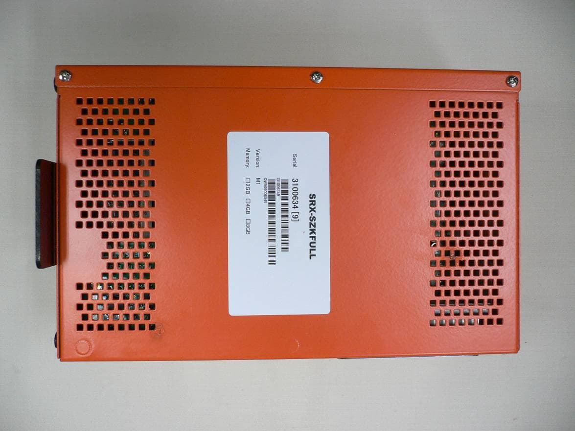
Click to zoom
Application Details
- Equipment Class
- DXX - Part 15 Low Power Communication Device Transmitter
- Date of Grant
- Feb 04, 2015
- Application Purpose
- Original Equipment
- Date of Application
- Feb 04, 2015
- Equipment Note
- IS-SNAKE-BOX
- Frequency Range
- 13.56000000 - 13.56000000
- Company
- INTELLIGENT SYSTEMS Co.,Ltd.
- Country
- Japan
Documents & Files
Document Text
Text extracted from the exhibit documents filed with the FCC. Open a document above to read the original.
Users Manual
2014 Nintendo CTR-XX-XXXX-XXX-X CONFIDENTIAL Released: August 7, 2014 IS-SNAKE DevKit Setup Manual 2014/08/07 Version 1.0 The content of this document is highly confidential and should be handled accordingly. IS-SNAKE DevKit Setup Manual CTR-XX-XXXX-XXX-X 2 2014 Nintendo Released: August 7, 2014 CONFIDENTIAL Confidential These coded instructions, statements, and computer programs contain proprietary information of Nintendo and/or its licensed developers and are protected by national and international copyright laws. They may not be disclosed to third parties or copied or duplicated in any form, in whole or in part, without the prior written consent of Nintendo. IS-SNAKE DevKit Setup Manual 2014 Nintendo 3 CTR-XX-XXXX-XXX-X CONFIDENTIAL Released: August 7, 2014 Table of Contents 1 Introduction .................................................................................................................................................. 4 2 Health and Safety Information ..................................................................................................................... 5 3 Notes ............................................................................................................................................................ 7 4 Operating Environment ................................................................................................................................ 8 5 Setup ............................................................................................................................................................ 9 5.1 Downloading the Software .................................................................................................................... 9 5.2 Software Installation ............................................................................................................................. 9 5.3 Uninstalling the Software ...................................................................................................................... 9 5.4 Fastening the IS-SNAKE-BOX Stand ................................................................................................. 10 5.5 Attaching the Ferrite Cores .................................................................................................................. 11 5.6 Installing Batteries .............................................................................................................................. 12 5.7 Replacing the Batteries ...................................................................................................................... 13 5.8 Connecting the Hardware ................................................................................................................... 13 5.9 Turning the Power On and Off ............................................................................................................ 15 5.10 Activating the License ......................................................................................................................... 16 6 Support ...................................................................................................................................................... 17 6.1 Website ............................................................................................................................................... 17 6.2 Email Support ..................................................................................................................................... 17 7 FCC and Industry Canada Information ...................................................................................................... 18 Revision History ................................................................................................................................................ 20 IS-SNAKE DevKit Setup Manual CTR-XX-XXXX-XXX-X 4 2014 Nintendo Released: August 7, 2014 CONFIDENTIAL 1 Introduction Thank you very much for purchasing the IS-SNAKE DevKit. This manual provides important information for you to read before using the IS-SNAKE DevKit and setup procedures. Be sure to read this manual before using the product. Keep this manual in a safe place so it can be readily accessed after setup is complete. IS-SNAKE DevKit Setup Manual 2014 Nintendo 5 CTR-XX-XXXX-XXX-X CONFIDENTIAL Released: August 7, 2014 2 Health and Safety Information To use IS-SNAKE DevKit safely, please read the following items carefully to ensure the unit does not malfunction and possibly cause a safety hazard. Do not modify or take apart the device. Doing so may result in electrocution, fire, or damage to the product or other objects. If you notice a problem, immediately stop using the unit. If the device emits any smoke, odors, or unusual sounds, promptly turn off the power switch, unplug the AC Adapter from the wall, and stop using the device. Do not allow liquids or foreign objects to enter the unit. Doing so may result in electrocution, fire, or damage to the product or other objects. Do not use the product while your hands are wet. Doing so may result in electrocution or burns. Never cover the unit or block ventilation. Doing so may result in fire. Make sure the controller is securely connected. Make sure the controller is securely connected to the controller cable. The connector could become damaged if it is loose. Do not damage the cables. Do not crimp, pull, or twist the cables. Doing so may result in electrocution. Do not subject the unit to strong impact. Do not hit the unit with anything or drop anything on it. Doing so may result in malfunction or damage. Do not place the unit in a humid or dusty location. Do not use or store the unit in a humid or dusty location. Doing so may result in electrocution. Do not use the unit in locations where the temperature is below 0° C or above 40° C. Do not use the unit areas with high temperatures and humidity, or where cond…
Text truncated - open the document above for the full version.
External Photos
CONFIDENCIAL October 6, 2014 INTELLIGENT SYSTEMS CO.,LTD. Photograph 1: SRX-SZKFULL (Front side) Photograph 2: SRX-SZKFULL (Right side) CONFIDENCIAL October 6, 2014 INTELLIGENT SYSTEMS CO.,LTD. Photograph 3: SRX-SZKFULL (Back side) Photograph 4: SRX-SZKFULL (Left side) CONFIDENCIAL October 6, 2014 INTELLIGENT SYSTEMS CO.,LTD. Photograph 5: SRX-SZKFULL (Top side) Photograph 6: SRX-SZKFULL (Bottom side) CONFIDENCIAL October 6, 2014 INTELLIGENT SYSTEMS CO.,LTD. Photograph 7: Controller for SRX-SZKFULL (Opened state) Photograph 8: Controller for SRX-SZKFULL (Back side)
ID Label/Location Info
February 5, 2015 INTELLIGENT SYSTEMS CO.,LTD. Label Format Label Image February 5, 2015 INTELLIGENT SYSTEMS CO.,LTD. Label Location This Label Image was T.B.D. So, please see location only.
Internal Photos
CONFIDENCIAL October 23, 2014 INTELLIGENT SYSTEMS CO.,LTD. Photograph 1: Controller for SRX-SZKFULL (Front side) Photograph 2: Controller for SRX-SZKFULL (Back side) NFC
Test Report
A-001-14-C (FCC ID: SRX-SZK001) Page 2 of 21 Report Version: A KEC Testing Division Table of Contents 0. REVISION HISTORY ........................................................................................................................................ 3 1. LABORATORY INFORMATION ..................................................................................................................... 4 1.1. Laboratory Accreditation .............................................................................................................................. 4 1.2. Test Facility .................................................................................................................................................. 4 1.3. Measurement Uncertainty ............................................................................................................................. 4 2. GENERAL INFORMATION ............................................................................................................................. 5 2.1. Product Description ...................................................................................................................................... 5 3. TESTED SYSTEM .............................................................................................................................................. 6 3.1. Reference Rule and Specification ................................................................................................................. 6 3.2. Date of Test ................................................................................................................................................... 6 3.3. Deviation of Standard ................................................................................................................................... 6 3.4. Test Mode ..................................................................................................................................................... 6 3.5. Block Diagram of TEST System .................................................................................................................. 7 3.6. List of Test System ....................................................................................................................................... 8 3.7. List of Cables ................................................................................................................................................ 8 4. AC POWER LINE CONDUCTED EMISSION MEASUREMENT .............................................................. 9 4.1. Test Procedure .............................................................................................................................................. 9 4.2. Test Results ................................................................................................................................................. 10 5. Radiated Emission (The Frequency Range of 9kHz to 30MHz) .................................................................... 12 5.1. Test Procedure ............................................................................................................................................ 12 5.2. Test Results ................................................................................................................................................. 13 6. Radiated Emission (The Frequency Range of above 30MHz) ....................................................................... 14 6.1. Test Procedure ............................................................................................................................................ 14 6.2. Test Results ................................................................................................................................................. 15 7. 20dB BANDWIDTH MEASUREMENT ......................................................................................................... 18 7.1. Test Procedure ............................................................................................................................................ 18 7.2. Test Results ................................................................................................................................................. 18 8. FREQUENCY TOLERANCE OF CARRIER SIGNAL ................................................................................ 19 8.1. Test Procedure ............................................................................................................................................ 19 8.2. Test Results ................................................................................................................................................. 20 9. TEST EQUIPMENT ......................................................................................................................................... 21 A-001-14-C (FCC ID: SRX-SZK001) Page 3 of 21 Report Version: A KEC Testing Division 0. REVISION HISTORY Report Version Page Description Date of Issue A - Initial issue of report 30 June 2014 A-001-14-C (FCC ID: SRX-SZK001) Page 4 of 21 Report Version: A KEC Testing Division 1. LABORATORY INFORMATION 1.1. Laboratory Accreditation The KEC has been accredited by the following organizations based on their criteria for testing laboratory (ISO/IEC 17025). (1) American Association for Laboratory Accreditation (A2LA) : Accreditation Number: 2070.01 (2) Japan Accreditation Board for Conformity Assessment (JAB) : Accreditation Number: RTL02810 (3) Voluntary EMC Laboratory Accreditation Center Inc. (VLAC) : Accreditation Number: VLAC-005 1.2. Test Facility All tests described in this report were performed by: Name: KEC Electronic Industry Development Center Testing Division Address: 3-2-2, Hikari-dai, Seika-cho, Soraku-gun, Kyoto 619-0237 Japan Anechoic Chamber : No.1 No.2 No.3 No.6 No.7 No.8 No.9 No.10 No.11 No.12 Shielded Room : No.1 No.7 …
Text truncated - open the document above for the full version.
Test Setup Photos
A-001-14-C (FCC ID: SRX-SZK001) Page 1 of 3 KEC Testing Division 1. APPENDIX Photographs of EUT System Configuration AC Power Line Conducted Emission Measurement A-001-14-C (FCC ID: SRX-SZK001) Page 2 of 3 KEC Testing Division Spurious Emissions Measurement (Radiated) (X axis) (Y axis) (Z axis) A-001-14-C (FCC ID: SRX-SZK001) Page 3 of 3 KEC Testing Division
Contact Information
Applicant
Takeshi Narita
Technical Contact
TUV Rheinland Japan Ltd.Miyuki Tamura
[email protected]+81459143888
4-25-2 Kita-Yamata · Yokohama · Japan
Test Firm
KEC Electronic Industry Development CenterSeiichi Izumi
Technical Specifications
| # | Rule Parts | Frequency Range | Power Output |
|---|---|---|---|
| 1 | 15C | 13.56 MHz - 13.56 MHz | - |
Other Applications from INTELLIGENT SYSTEMS Co.,Ltd.
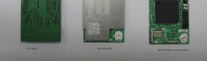
SRX-FULLW001
Feb 04, 2015WLAN Module
Equipment Class
DTS - Digital Transmission System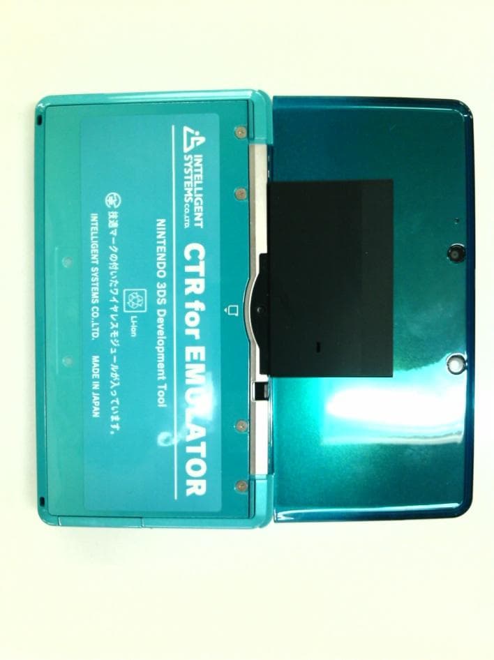
SRX-ISJRLMC
Sep 05, 2011Game Development Tool
Equipment Class
DTS - Digital Transmission System