SRX-ISJRLMCGame Development Tool
INTELLIGENT SYSTEMS Co.,Ltd.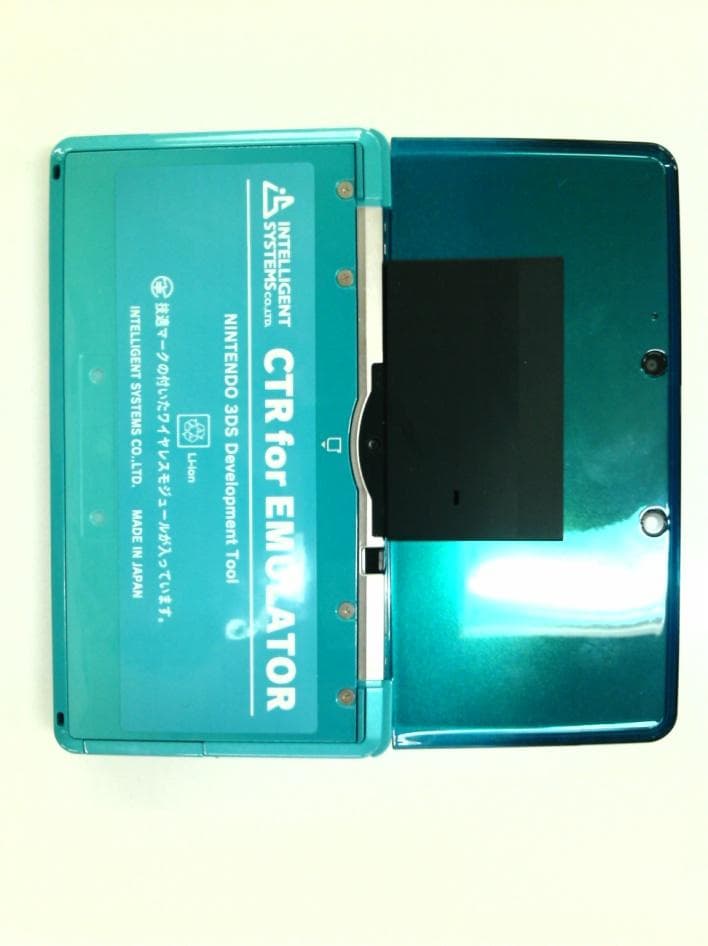
Click to zoom
Application Details
- Equipment Class
- DTS - Digital Transmission System
- Date of Grant
- Sep 05, 2011
- Application Purpose
- Original Equipment
- Date of Application
- Jun 28, 2011
- Equipment Note
- Game Development Tool
- Frequency Range
- 2412.00000000 - 2472.00000000
- Company
- INTELLIGENT SYSTEMS Co.,Ltd.
- Country
- Japan
Documents & Files
Document Text
Text extracted from the exhibit documents filed with the FCC. Open a document above to read the original.
Users Manual
CONFIDENTIAL June 28, 2011 IS-CTR-DEBUGGER Packing List IS-CTR-DEBUGGER includes the following items. Please confirm that all content is included before using. Hardware IS-CTR-BOX 1 CTR for EMULATOR 1 Accessories CTR for EMULATOR Cable 1 AC Adapter (RVL-002) 1 USB Cable 1 Nintendo 3DS Stylus (in the CTR for EMULATOR) 1 IS-CTR-BOX screw type stand (with two screws) 1 Ferrite Core (made by SEIWA ELECTRIC MFG. CO.,LTD.) 2 Software INTELLIGENT SYSTEMS Development Kit for CTR (CD-ROM) 1 Document Set-Up Manual 1 User Agreement 1 * SD card is not included
Users Manual
CONFIDENTIAL IS-CTR-DEBUGGER Set-up Manual INTELLIGENT SYSTEMS CO.,LTD. June 28, 2011 IS-CTR-BOX Set-up Manual CONFIDENTIAL Version 0.0.2 2 Packing List Packing List Hardware IS-CTR-BOX 1 CTR for EMULATOR 1 Software INTELLIGENT SYSTEMS Development Kit for CTR (CD-ROM) 1 Accessories CTR for EMULATOR Cable 1 AC Adapter (RVL-002) 1 USB Cable 1 Nintendo 3DS Stylus (in the CTR for EMULATOR) 1 IS-CTR-BOX screw type stand (with two screws) 1 Ferrite Core (made by SEIWA ELECTRIC MFG. CO.,LTD.) 2 IS-CTR-BOX Set-up Manual CONFIDENTIAL Version 0.0.2 3 Using This Product Safely Regulatory Statement This equipment has been tested and found to comply with the limits for a Class A digital device, pursuant to part 15 of the FCC Rules. These limits are designed to provide reasonable protection against harmful interference when the equipment is operated in a commercial environment. This equipment generates, uses, and can radiate radio frequency energy and, if not installed and used in accordance with the instruction manual, may cause harmful interference to radio communications. Operation of this equipment in a residential area is likely to cause harmful interference in which case the user will be required to correct the interference at their own expense. This equipment complies with FCC radiation exposure limits for an uncontrolled environment. Properly shielded and grounded cables and connectors must be used for connection to host computers and / or peripherals in order to meet FCC emission limits. And the ground cable must be less than 3m. AC adaptor with ferrite core must be used for RF interference suppression. This equipment complies with FCC radiation exposure limits set forth for a controlled environment and meets the FCC radio frequency (RF) Exposure Guidelines in Supplement C to OET65. This equipment has very low levels of RF energy that are deemed to comply without testing of specific absorption ratio (SAR). Modifications made to the product, unless expressly approved by INTELLIGENT SYSTEMS, could void the user’s right to operate the equipment. IS-CTR-BOX Set-up Manual CONFIDENTIAL Version 0.0.2 4 Special Notes Notes Note the following when using IS-CTR-DEBUGGER Do not turn off the IS-CTR-BOX device during firmware updates. The IS-CTR-BOX device may not function properly afterward. During use, do not do anything that would prevent heat dissipation, such as blocking the IS-CTR-BOX airflow vent, placing the IS-CTR-BOX in a closed container, or placing objects on top of the IS-CTR-BOX. Connect the CTR for EMULATOR to IS-CTR-BOX. Connect the plug with the green band to the IS-CTR-BOX and the plug with the black band to the CTR for EMULATOR. Be sure to tighten the connector screws. When the IS-CTR-BOX device is sent to INTELLIGENT SYSTEMS for repairs or to add options, the system menu may be updated. Please back up your data and settings before sending in the device. Also, reconfigure the device after it is returned and before using it. The liquid crystal display may already have pixels that are illuminated or that do not illuminate. Also, you might observe irregularity in color or brightness, depending on the angle of view. These are properties of the liquid crystal display and are not defects. IS-CTR-BOX Set-up Manual CONFIDENTIAL Version 0.0.2 5 Operation Environment Requirements The following components are required to operate the IS-CTR-DEBUGGER by connecting it to a computer. Component Description Computer PC/AT-compatible Operating system One of the following operating systems must be installed: Microsoft® Windows® 7 32-bit version, 64-bit version Microsoft® Windows Vista® Service Pack 2 or later, 32bit version, 64-bit version Microsoft® Windows® XP 32-bit、64-bit version, Service Pack 3 or later Memory capacity As recommended by the operating system or greater. More memory than that recommended by the OS may sometimes be required, depending on the operating environment. Disk capacity 50MB or more of free memory Optical disc drive Drive capable of reading a CD-ROM at installation display XGA display with a 1024x768 resolution or higher USB interface One port required (USB 2.0 high-speed is recommended.) Software Environment Microsoft Windows Installer 3.1 or later Microsoft .NET Framework Version 3.5 SP1 or later IS-CTR-BOX Set-up Manual CONFIDENTIAL Version 0.0.2 6 Set-up Installing the Software To install IS-CTR Software Package onto a computer: Note: IS-CTR Software Package include following software IS-CTR-MONO WRITER IS-CTR-EMULATOR IS-CTR-DEBUGGER 1. Log on Windows as a user with an Administrator account on the computer. 2. Exit all currently running programs. 3. "INTELLIGENT SYSTEMS Development Kit for CTR" CD-ROM Please insert the CD-ROM drive. 4. INTELLIGENT SYSTEMS Development Kit for CTR menu starts automatically. Please click the IS-CTR Software Package Install in the menu. 5. Follow the displayed instructions. If the installation program completes normally, installation ends. If prompted, restart the computer after installation completes. Uninstalling the Software To uninstall the IS-CTR Software Package from a computer: Note: IS-CTR Software Package include following software IS-CTR-MONO WRITER IS-CTR-EMULATOR IS-CTR-DEBUGGER 1. Log on Windows as a user with an Administrator account on the computer. 2. If the IS-CTR-MONO WRITER or IS-CTR-EMULATOR or IS-CTR-DEBUGGER is running, exit the software. 3. In Control Panel, click Programs and Features to open the Remove or Change Programs dialog box. (For Windows XP, click Add or Remove Programs to display the Add or Remove Programs dialog box.) 4. Select IS-CTR Software Package from the list of installed programs. 5. Crick Delete to start deleting the IS-CTR Software Package. If deletion completes normally, the IS-CTR Software Package has been uninstalled. Uninstalling does not delete option settings and window position information. For this reason, the last state can be used even when uninsta…
Text truncated - open the document above for the full version.
Users Manual
User Manual MITSUMI WiFi Module MODEL DWM-W028 The purpose of this manual is to explain correct way how to integrate module DWM-W028 to the end product. It includes procedures that shall assist you to avoid unforeseen problems. This manual presents information that shows how module and OEM product, where module integrated, complies with regulations in certain regions. Any modifications, not expressly approved by the manufacturer could void the authority to operate in these regions. The MITSUMI WiFi Module, model DWM-W028 has to be installed and used in accordance with the technical description/installation instructions provided by the manufacturer. For detail information concerning type approval of this module (e.g. where this module is already pre-approved) please contact the authorized local distributor or the manufacturer. The system may only be implemented in the configuration that was authorized. Note that any changes or modifications to this equipment not expressly approved by the manufacturer could void the user’s authority to operate this equipment. Regulatory Information Operational Information Wireless Interoperability The end product integrating this module is designed to be interoperable with any wireless LAN product that is based on direct sequence spread spectrum (DSSS) and orthogonal frequency division multiplexing (OFDM) radio technology and to comply with the following standards. z IEEE Std 802.11b Standard on 2.4GHz Wireless LAN z IEEE Std 802.11g Standard on 2.4GHz Wireless LAN Safety The end product integrating this module, like other radio devices, emits radio frequency electromagnetic energy. The level of energy emitted by this device, however, is less than the electromagnetic energy emitted by other wireless devices such as mobile phones. The end product integrating this module operates within the guidelines found in radio frequency safety standards and recommendations. These standards and recommendations reflect the consensus of the scientific community and result from deliberations of panels and committees of scientists who continually review and interpret the extensive research literature. In some situations or environments, the use of the end product integrating this module may be restricted by the proprietor of the building or responsible representatives of the applicable organization. Examples of such situations include the following: z Using the end product integrating this module onboard airplanes, or z Using the end product integrating this module in any other environment where the risk of interference with other devices or services is perceived or identified as being harmful. If uncertain of the policy that applies to the use of wireless devices in a specific organization or environment (an airplane, for example), ask for authorization to use the end product integrated into this module before turning it on. USA-Federal Communications Commission (FCC) This equipment has been tested and found to comply with the limits for a Class B digital device, pursuant to Part 15 of FCC Rules. These limits are designed to provide reasonable protection against harmful interference in a residential installation. This equipment generates, uses, and can radiate radio frequency energy. If not installed and used in accordance with the instructions, it may cause harmful interference to radio communications. However, there is no guarantee that interference will not occur in a particular installation. If this equipment does cause harmful interference to radio or television reception, which can be determined by tuning the equipment off and on, the user is encouraged to try and correct the interference by one or more of the following measures: z Reorient or relocate the receiving antenna. z Increase the distance between the equipment and the receiver. z Connect the equipment to outlet on a circuit different from that to which the receiver is connected. z Consult the dealer or an experienced radio/TV technician for help. This device complies with Part 15 of the FCC Rules. Operation is subject to the following two conditions: (1) This device may not cause harmful interference, and (2) This device must accept any interference received, including interference that may cause undesired operation. Any changes or modifications not expressly approved by the party responsible for compliance could void the user’s authority to operate the equipment. Labeling MITSUMI WiFi module DWM-W028 labeled as below. FCC ID: EW4DWMW028 The proposed with FCC ID label format is to be placed on the module. If FCC ID is not visible when the module is installed into the system, “Contains FCC ID: EW4DWMW028” shall be placed on the outside of final host system. Caution: Exposure to Radio Frequency Radiation. Minimum 20cm safe separation distance warning required for the module which must comply with RF exposure requirement. Canada-Industry Canada (IC) This device complies with RSS-210 of Industry Canada. Operation is subject to the following two conditions: (1) This device may not cause interference, and (2) This device must accept any interference, including interference that may cause undesired operation of this device. L ‘ utilization de ce dispositif est autorisée seulement aux conditions suivantes : (1) il ne doit pas produire de brouillage et (2) l’ utilisateur du dispositif doit étre prêt à accepter tout brouillage adioélectrique reçu, même si ce brouillage est susceptible de compromettre le fomctionnement du dispositif. The term “IC” before the equipment certification number only signifies that the Industry Canada technical specifications were met. To reduce potential radio interference to other users, only the authorized antenna type and its gain should be so chosen that the equivalent isotropic radiated power (EIRP) is not more than that required for successful communication. To prevent radio interference to the licensed service, this device is intended to be operated indoors and away from windows to p…
Text truncated - open the document above for the full version.
External Photos
CONFIDENTIAL External Pictures Top view (ISJ-DEBUGGER) Bottom view (ISJ-DEBUGGER) CONFIDENTIAL Front view (ISJ-DEBUGGER) CONFIDENTIAL Back view (ISJ-DEBUGGER) CONFIDENTIAL Left rear view (ISJ-DEBUGGER) Right rear view (ISJ-DEBUGGER) CONFIDENTIAL Top view (ISJ-RLMC) Bottom view (ISJ-RLMC) CONFIDENTIAL Front view (ISJ-RLMC) Back view (ISJ-RLMC) CONFIDENTIAL Left rear view (ISJ-RLMC) Right rear view (ISJ-RLMC) CONFIDENTIAL Top view (Open ISJ-RLMC) Bottom view (Open ISJ-RLMC) CONFIDENTIAL Front view (Open ISJ-RLMC) Back view (Open ISJ-RLMC) CONFIDENTIAL Left rear view (Open ISJ-RLMC) Right rear view (Open ISJ-RLMC)
ID Label/Location Info
CONFIDENTIAL Label Format Label Location Model: SRX-ISJ V: 12V A: 3.7A ・FCC ID: SRX-ISJRLMC Contains FCC ID: EW4DWMW028 This Class A device complies with part 15 of the FCC Rules. Operation is subject to the following two conditions: (1) This Class A device may not cause harmful interference, and (2) this Class A device must accept any interference received,including interference that may cause undesired operation. ・IC: 5567A-ISJRLMC Contains IC: 4250A-DWMW028 This Class A digital apparatus complies with Canadian ICES-003, and RSS-210. Cet appareil numérique de la classe A est conforme à la norme NMB-003, et CNR-210 du Canada. NINTENDO 3DS Development Tool CTR for EMULATOR 技適マークの付いたワイヤレスモジュールが入っています。 Li-ion INTELLIGENT SYSTEMS CO.,LTD. MADE IN JAPAN T.B.D. T.B. 2011/6/29
Internal Photos
CONFIDENTIAL Internal Pictures Front view (ISJ DEBUGGER PCB) Reverse view (ISJ DEBUGGER PCB) CONFIDENTIAL Front view (ISJ CARD PCB) Reverse view (ISJ CARD PCB) CONFIDENTIAL Front view (ISJ POW PCB) Reverse view (ISJ POW PCB) CONFIDENTIAL Front view (ISJ-RLMC-01 PCB) Reverse view (ISJ-RLMC-01 PCB) CONFIDENTIAL Internal Pictures for Radio Front view (Module) Reverse view (Module with shielding) CONFIDENTIAL Reverse view (Module without shielding)
RF Exposure Info
FCC ID: EW4DWMW028 IC: 4250A-DWMW028 Produkte Products RF Exposure Statement: 12606802 008 Page 1 of 1 Client: Mitsumi Electric Co Ltd 1601, Sakai, Atsugi-shi. Kanagawa-ken 243, Japan Test item: Wireless LAN Module Identification: DWM-W028 No SAR Evaluation Required for FCC if power is below the following threshold: Tunable Range Lowest frequency [GHz] Highest frequency [GHz] Center of Tunable Band [GHz] 60/f SAR Limitation mW based on center of band 2.412 2.472 2.442 24.57 No SAR Evaluation Required for IC if power is below the following threshold: Above 2.2 GHz and up to 3 GHz inclusively, and with output power (i.e. the higher of the conducted or radiated (e.i.r.p.) source-based, time-averaged output power) that is less than or equal to 20 mW for general public use and 100 mW for controlled use; Maximum measured transmitter power: Average power output, conducted [mW] Maximum antenna gain [dBi] Power output, EIRP [mW] 802.11b: 2.74 802.11g: 2.96 For the host: Nintendo DS CTR Target Board DCA-P08: -1.91dBi For the host: CTR-001(-01) DCA-P17 ES3: -6.52dBi DCA-P17 ES4: -6.20dBi DCA-P17 CS: -6.35dBi 361.00194.005 CS: +1.15dBi For the host: CTR-001 / CTR-001(-01) DCA-P17 CS2: -5.39dBi 361.00194.005 CS2: -5.10dBi 3.86 (Worst case) Threshold(FCC) for no SAR evaluation is 24.57mW Threshold(IC) for no SAR evaluation is 20mW for general public use Maximum Tx Average Power is 2.96mW (Conducted) and 3.86mW (EIRP) Conclusion: No SAR evaluation is required since maximum Transmitter Power output (both conducted and EIRP) is below threshold Please refer to test report 12606802 007 for more details. TÜV Rheinland Japan Ltd. - Global Technology Assessment Center 4-25-2 Kita-Yamata, Tsuzuki-ku, Yokohama 224-0021, Japan
Test Report
KEC Testing Division A-003-11-A Page 1 of 16 KEC ELECTRONIC INDUSTRY DEVELOPMENT CENTER TEST REPORT Report Number : A-003-11-A Date of Issue: 21 June 2011 FCC Rules and Regulations Part 15 Subpart B Unintentional Radiators This test report is to certify that the device was tested according to the requirements of the above and these results met the specifications of requirements. The results of this report should not be construed to imply compliance of devices other than the sample tested. Without the laboratory approval by the documents, this report should not be copied in part. 1. Applicant Company Name : INTELLIGENT SYSTEMS CO.,LTD. Mailing Address : 60 Kamitakamatsu-cho Fukuine Higashiyama-ku Kyoto-shi Kyoto-fu 605-0983 Japan 2. Identification of Tested Device Type of Device : Personal Computer and Peripherals FCC ID : Not Applicable Device Name : IS-CTR-DEBUGGER Model Number : SRX-ISJ Serial Number : 2100045-1 Trade Name : INTELLIGENT SYSTEMS CO.,LTD. Type of Test : Production Pre-production Prototype 3. Test Items and Procedure AC Power Line Conducted Emission Measurement Radiated Emission Measurement Above all tests were performed under: ANSI C63.4-2003 without deviation, with deviation (details are found inside of this report) 4. Date of Test Receipt of Test Sample : 2 June 2011 Condition of Test Sample : Damage is not found on the set. Damage is found on the set. (Details are described in this report) Test Completed on : 17 June 2011 Test Engineer(s) Naoki Norimoto Approved byIkuya Minematsu / Assistant Group Manager KEC Testing Division A-003-11-A Page 2 of 16 Table of Contents 1. LABORATORY ACCREDITATION AND MEASUREMENT UNCERTAINTY ....................................... 3 1.1. Laboratory Accreditation ............................................................................................................................... 3 1.2. Measurement Uncertainty ............................................................................................................................. 3 2. CERTIFICATION OF THE COMPLIANCE ................................................................................................. 3 3. GENERAL INFORMATION ............................................................................................................................ 4 3.1. Product Description ....................................................................................................................................... 4 3.2. Description for Equipment Authorization ..................................................................................................... 5 3.3. Test Facility ................................................................................................................................................... 5 4. TESTED SYSTEM ............................................................................................................................................. 6 4.1. Test Mode ...................................................................................................................................................... 6 4.2. Characterization and condition of EUT System ............................................................................................ 6 4.3. Block Diagram of EUT System ..................................................................................................................... 6 4.4. List of EUT System ....................................................................................................................................... 7 4.5. List of Cables ................................................................................................................................................ 7 5. AC POWER LINE CONDUCTED EMISSION MEASUREMENT ............................................................. 8 5.1. Test Procedure ............................................................................................................................................... 8 5.2. Test Results ................................................................................................................................................... 9 5.3. Photographs of EUT System Configuration ................................................................................................ 11 6. RADIATED EMISSION MEASUREMENT ................................................................................................. 12 6.1. Test Procedure ............................................................................................................................................. 12 6.2. Test Results ................................................................................................................................................. 13 6.3. Photographs of EUT System Configuration ................................................................................................ 15 7. USED TEST EQUIPMENT AND CALIBRATION STATUS ...................................................................... 16 KEC Testing Division A-003-11-A Page 3 of 16 1. LABORATORY ACCREDITATION AND MEASUREMENT UNCERTAINTY 1.1. Laboratory Accreditation KEC is accredited by the Voluntary EMC Laboratory Accreditation Center Inc. (VLAC) for the specific scope of accreditation under Lab Code: VLAC-005. When the test report concerns with the VLAC accreditation test, the first page of the test report is signed by VLAC Approved Signatory accompanied by the VLAC logo. The report must not be used by the client to claim product endorsement by VLAC or any agency of the U.S. Government. 1.2. Measurement Uncertainty The result of a measurement is only an approximation or estimate of the value of a specific quantity. And thus the measurand is complete only when a statement of uncertainty is given. KEC quotes Measurement Uncertainty (U) as follows. Measurement of Conducted Disturbance Mains Ports : +3.1/-3.7 dB Telecommunication Ports ISN method : …
Text truncated - open the document above for the full version.
Test Setup Photos
KEC Testing Division A-009-11-B2 Page 1 of 15 KEC ELECTRONIC INDUSTRY DEVELOPMENT CENTER TEST REPORT Report Number : A-009-11-B2 Date of Issue: 21 June 2011 Industry Canada Standard ICES-003 Issue 4 Digital Apparatus This test report is to certify that the device was tested according to the requirements of the above and these results met the specifications of requirements. The results of this report should not be construed to imply compliance of devices other than the sample tested. Without the laboratory approval by the documents, this report should not be copied in part. 1. Applicant Company Name : INTELLIGENT SYSTEMS CO.,LTD. Mailing Address : 60 Kamitakamatsu-cho Fukuine Higashiyama-ku Kyoto-shi Kyoto-fu 605-0983 Japan 2. Identification of Tested Device Type of Device : Personal Computer and Peripherals Device Name : IS-CTR-DEBUGGER Model Number : SRX-ISJ Serial Number : 2100045-1 Trade Name : INTELLIGENT SYSTEMS CO.,LTD. Type of Test : Production Pre-production Prototype 3. Test Items and Procedure AC Power Line Conducted Emission Measurement Radiated Emission Measurement Above all tests were performed under: CSA Standard CAN/CSA-CEI/IEC CISPR22:02 without deviation, with deviation (details are found inside of this report) 4. Date of Test Receipt of Test Sample : 2 June 2011 Condition of Test Sample : Damage is not found on the set. Damage is found on the set. (Details are described in this report) Test Completed on : 17 June 2011 Test Engineer(s) Naoki Norimoto Approved byIkuya Minematsu / Assistant Group Manager KEC Testing Division A-009-11-B2 Page 2 of 15 Table of Contents 1. MEASUREMENT UNCERTAINTY ................................................................................................................ 3 1.1. Measurement Uncertainty ............................................................................................................................. 3 2. CERTIFICATION OF THE COMPLIANCE ................................................................................................. 3 3. GENERAL INFORMATION ............................................................................................................................ 4 3.1. Product Description ....................................................................................................................................... 4 3.2. Description for Equipment Authorization ..................................................................................................... 4 3.3. Test Facility ................................................................................................................................................... 4 4. TESTED SYSTEM ............................................................................................................................................. 5 4.1. Test Mode ...................................................................................................................................................... 5 4.2. Characterization and condition of EUT System ............................................................................................ 5 4.3. Block Diagram of EUT System ..................................................................................................................... 5 4.4. List of EUT System ....................................................................................................................................... 6 4.5. List of Cables ................................................................................................................................................ 6 5. AC POWER LINE CONDUCTED EMISSION MEASUREMENT ............................................................. 7 5.1. Test Procedure ............................................................................................................................................... 7 5.2. Test Results ................................................................................................................................................... 8 5.3. Photographs of EUT System Configuration ................................................................................................ 10 6. RADIATED EMISSION MEASUREMENT .................................................................................................. 11 6.1. Test Procedure ............................................................................................................................................. 11 6.2. Test Results ................................................................................................................................................. 12 6.3. Photographs of EUT System Configuration ................................................................................................ 14 7. USED TEST EQUIPMENT AND CALIBRATION STATUS ...................................................................... 15 KEC Testing Division A-009-11-B2 Page 3 of 15 1. MEASUREMENT UNCERTAINTY 1.1. Measurement Uncertainty The result of a measurement is only an approximation or estimate of the value of a specific quantity. And thus the measurand is complete only when a statement of uncertainty is given. KEC quotes Measurement Uncertainty (U) as follows. Measurement of Conducted Disturbance Mains Ports : +3.1/-3.7 dB Telecommunication Ports ISN method : +2.8/-3.4 dB Telecommunication Ports Current Probe method : +2.3/-2.8 dB Telecommunication Ports 150Ω load voltage method : +2.3/-2.8 dB Lead Terminals and Additional Terminals : +2.1/-2.6 dB Measurement of Disturbance Power : +2.6/-3.5 dB Measurement of Radiated Disturbance Frequency Range (9 kHz – 30 MHz) : +3.6/-4.2 dB Frequency Range (30 MHz – 1000 MHz) : +4.2/-4.8 dB Frequency Range (1 GHz – 6 GHz) : +4.5/-5.9 dB Frequency Range (6 GHz – 26.5 GHz) : +5.4/-5.7 dB Harmonic Currents Emissions : +0.5/-0.5 dB Voltage Changes, Voltage Fluctuations and Flicker : +0.7/-0.7 dB Above values are calculated a…
Text truncated - open the document above for the full version.
Contact Information
Applicant
Takeshi Narita
Test Firm
KEC Electronic Industry Development CenterKenji Masaoka
Technical Specifications
| # | Rule Parts | Frequency Range | Power Output |
|---|---|---|---|
| 1 | 15C | 2.41 GHz - 2.47 GHz | 30.30 mW |
Other Applications from INTELLIGENT SYSTEMS Co.,Ltd.
SRX-SZK001
Feb 04, 2015IS-SNAKE-BOX
Equipment Class
DXX - Part 15 Low Power Communication Device Transmitter
SRX-FULLW001
Feb 04, 2015WLAN Module
Equipment Class
DTS - Digital Transmission System