SSULD20D200SME LD-20D Leak Tracker Remote Control Unit
Solutions Made Easy Limited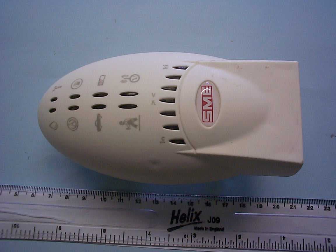
Click to zoom
Application Details
- Equipment Class
- DXX - Part 15 Low Power Communication Device Transmitter
- Date of Grant
- Dec 14, 2005
- Application Purpose
- Original Equipment
- Date of Application
- Dec 14, 2005
- Equipment Note
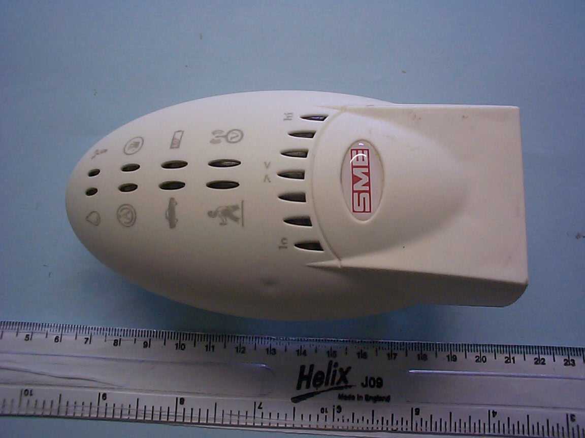
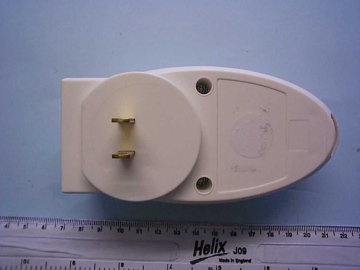
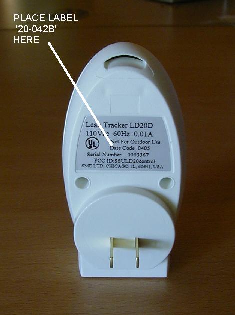
- SME LD-20D Leak Tracker Remote Control Unit
- Frequency Range
- 909.57400000 - 910.28600000
- Company
- Solutions Made Easy Limited
- Country
- United Kingdom
Documents & Files
Document Text
Text extracted from the exhibit documents filed with the FCC. Open a document above to read the original.
Users Manual
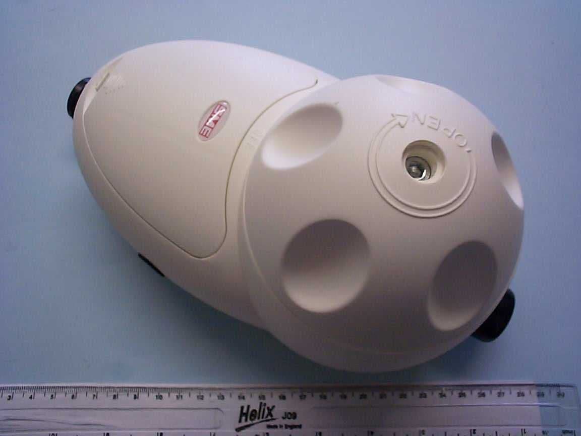
DETECTOR VALVE 1. Valve Charging Knob. This Control is used to “Recharge” the valve after it has closed. To achieve this carefully rotate the knob clockwise 90 degrees from the off position until it stops (this point is indicated on the body). Carefully release the knob and it will remain in position. 2. Valve Test Button. This is the Detector Valve test button and should only be used if you cannot reach the Remote Controller and need to shut off the incoming water supply. The valve must then be manually reset as described in (1) above. 3. Battery Cover. To remove the battery covers gently press the clip in the direction of the arrow and then pull upwards. The batteries require careful insertion to ensure the correct polarity and connection. Only use prime quality AA batteries and only replace a complete set of cells. Take extreme care in the use and disposal of batteries as there is a risk of fire or explosion if cells are not handled or disposed of correctly; the SME 110vac mains transformer is available as an optional extra. Issue 12 June 2005 Solutions Made Easy Limited 2850 North Pulaski Chicago, IL 60641, USA Free Phone 1800 621 1556 LEAK TRACKER LD-20D USER GUIDE 110VAC ONLY USE ONLY FCC ID : SSULD20D100 FCC ID: SSULD20D200 This device complies with Part 15 of the FCC Rules. Operation is subject to the following two conditions: (1)this device may not cause harmful interference, and (2) this device must accept any interference received, including interference that may cause undesired operation. IMPORTANT NOTE FOR HOUSE BUILDERS The LD20-D Leak Tracker has features which protect new homes during the final stages of construction prior to the “handover”. Once the LD20-D is installed it is recommended that the system is set to the Manual Mode (15 minute setting). If a higher degree of protection is required select the away mode This setting will only allow 2 minutes of high water flow and 10 minutes of low water flow (3gallons/hr or less) sufficient for cleaners, tradesmen and sales staff etc, to carry out their duties. In the event of a need for more water the valve can be simply reset to restart the water flow. To ensure the system is not tampered with or abused, the controller can be removed from the new home to a safe keeping place. The valve will still offer maximum protection but without the audible alarm feature. The incoming homeowner can then be presented with the controller & user guide instructions. The Remote Controller and Detector V alve are factory registered to each other and will only work together, serial numbers are affixed to both valve and controller for identification CONTROL BUTTONS Protective Button Cover Flap. (1) To ensure no accidental control inputs are made to the system keep the protective flap closed during normal use. Valve Close Button. (2) Press to shut off the incoming water supply. The valve must then be manually reset every time the Valve Close Button has been pressed. To ensure reliable service test once every month by pressing this button. Failure to do this will invalidate the Guarantee. Manual / Auto Mode Selector Button. (3) Press to select either Manual or Auto Mode. LEDs 15 or 11 (see diagram) will indicate which mode has been selected. Manual Time Adjust Button. (4) (Use in manual mode only) Pressing this button repeatedly will select the desired water flow time on the time display (7). This is the amount of time that water is allowed to flow continuously before the alarm is sounded indicating a problem. After a further 10 minutes the valve will close, shutting off the water supply if the reset button is not pressed to cancel the alarm. When in the manual mode should no flow occurs for 12 hr, the flow control time will automatically set to the minimum time setting of 15 minutes for added protection. The initial setting is then restored following the first usage of water. Away Mode Selector Button. (5) This mode should be selected if the property is to be left unoccupied for longer than 24 hrs. In the event of any abnormal flow or leak the water supply is closed after a period of 10 minutes on flows below 3 gallon/hour or 2 minutes where the water flow is higher, i.e. in the event of a significant leak or a burst pipe. Reset Button. (6) The Reset button is used to cancel an alarm signal or for cancelling any incorrect user input. MODES Auto Mode computes the best protection flow / time settings for an occupied property and collects your water use data for the ‘economiser’ function and stores the data in its memory. To automatically set up your system; press and hold down the manual/auto button (3) for 5 seconds, until the economiser lights (8) scroll up and down continuously. The lights will scroll up and down for the 48 hour sampling period. When a single time light remains illuminated the system has then auto- set. During this 48 hour learning period only flows exceeding 180 minutes duration will trigger an alarm. It is important that no other control inputs are made to the controller or valve during this set up period & that you use water wisely during the “set up” period to provide a low water use benchmark. Plumber Mode when a small non damaging leak such as a running toilet valve has been detected and a plumber is not immediately available to rectify the problem, press and hold the Reset (6) button until 2 audible “beeps” are heard then immediately press the Away button (5) and release. This plumber mode will remain active for 4 days; thereafter the system will revert to the previous setting. This mode can be cancelled by pressing the Reset button (6) at any time. Note: Water leaks above 3 gallons/m will alarm as normal in this setting . CONTROL LEDs Manual Time Display LEDs. (7) (15 - 180 minutes) Displays the chosen time setting when the manual control function is selected or the unit has auto set. Economiser Water Use Gage LEDs. (8) This function requires the unit to have been set in the Auto Set Up mode on commissioning or at a late…
Text truncated - open the document above for the full version.
Users Manual
...fläŒ ‘¤fl’ —Œ ...flÕä ◊“‹◊›fl׌ flÀ×”flÃ◊› ”—‹¤ ◊“‹◊›fl׌ fl...fl« ”—‹¤ ◊“‹◊›fl׌ –‘À”fi¤Œ ”—‹¤ ◊“‹◊›fl׌ ¤›—“—”◊Õ¤Œ ...fläŒ ÀÕ¤ ◊“‹◊›fl׌ Ã◊”¤ fl‹÷ÀÕà fiÀÃד flÀ× Ò ”fl“Àfl‘ ”—‹¤ Õ¤‘¤›Ã—Œ ̇ flÀ× դà À– fiÀÃד ...¤Ã Õ¤“Õ—Œ ‘¤fl’ fl‘flŒ” ◊“‹◊›fl׌ ”fl“Àfl‘ ”—‹¤ ◊“‹◊›fl׌ fiflÃ䌫 ‘—... ...flŒ“◊“Ÿ ◊“‹◊›fl׌ Œ⁄ ÃŒfl“Õ”◊ÕÕ◊—“ ⁄fl◊‘ÀŒ¤ ◊“‹◊›fl׌ ...fläŒ ⁄‘—... Ã◊”¤ ̄”◊“ÀÃ¤Õ ̃ ◊“‹◊›fl׌ Œ¤Õ¤Ã fiÀÃד fl...fl« ”—‹¤ fiÀÃד ¤”¤ŒŸ¤“›« ...fläŒ ÕÿÀà —⁄⁄ fiÀÃד ...∏ª≤ Æøº∑± Ω±≥≥ ́≤∑ΩøÛ ̈∑±≤ ∑≠ ª≠ ̈øæ¥∑≠∏ªº æª ̈©ªª≤ ø¥™ª ̇ ›±≤ ̈Ʊ¥¥ªÆ ̈∏ª ∑≤º∑Ωø ̈±Æ≠ ≠∏±©≤ ±∞∞±≠∑ ̈ª ©∑¥¥ ƪ≥ø∑≤ Ω±≤≠ ̈ø≤ ̈¥ß ∑¥¥ ́≥∑≤ø ̈ªº ∑≥≥ªº∑ø ̈ª¥ß ≥±™ª ̈± Õ ̈ª∞ Ì ÿ±©ª™ªÆ ≠∏± ́¥º Œ⁄ Ω±≥≥ ́≤∑Ωø ̈∑±≤ ≤± ̈ æª ª≠ ̈øæ¥∑≠∏ªº ̈∏∑≠ Œ⁄ ̈Æø≤≠≥∑≠≠∑±≤ ∫ø∑¥ ́ƪ ¥∑π∏ ̈ ̄ Á ̃ ©∑¥¥ ∑¥¥ ́≥∑≤ø ̈ª ∑≤ ©∏∑Ω∏ Ωø≠ª –ƪ≠≠ ø≤º Œª¥ªø≠ª ̈∏ª ƪ≠ª ̈ æ ́ ̈ ̈±≤ ̄ › ̃ ±≤ª 楪ª∞ ∑≠ ∏ªøƺ ◊∫ ø¥¥ ∑≤º∑Ωø ̈±Æ≠ øƪ ª® ̈∑≤π ́∑≠∏ªº ∞ƪ≠≠ ƪ≠ª ̈ æ ́ ̈ ̈±≤ øπø∑≤ ±≤Ωª ̈∏ª Ω±≤ ̈Ʊ¥¥ªÆ ©∑¥¥ ø ́ ̈±≥ø ̈∑Ωø¥¥ß ø ̈ ̈ª≥∞ ̈ ̈± ƪ۪≠ ̈øæ¥∑≠∏ Æøº∑± Ω±≤ ̈øΩ ̈ ‹± ≤± ̈ ∞¥øΩª ̈∏ª Ω±≤ ̈Ʊ¥¥ªÆ ∑≤ ̈± ø ∞±©ªÆ ≠±Ωμª ̈ æª∫±Æª ̈∏ª ø¥™ª ∑≠ ∫ ́¥¥ß ∑≤≠ ̈ø¥¥ªº ̇ æø ̈ ̈ªÆ∑ª≠ øƪ ∫∑ ̈ ̈ªº –¥øΩª ›±≤ ̈Ʊ¥¥ªÆ ∑≤ ̈± ø ÓÓÒÓÏ fl› ± ́ ̈¥ª ̈ ø≠ Ω¥±≠ª ̈± ̈∏ª ™ø¥™ª ø≠ ∞ÆøΩ ̈∑Ωø¥ º ́Æ∑≤π ≠ª ̈ ́∞ ̄Ã∏ª Ω±≤ ̈Ʊ¥¥ªÆ ≥øß æª Æª¥±Ωø ̈ªº ø∫ ̈ªÆ ≠ª ̈ ́∞ ̃ Ã∏ª ¥∑π∏ ̈≠ ±≤ ̈∏ª Ω±≤ ̈Ʊ¥¥ªÆ ©∑¥¥ è∫¥ø≠∏é ©∏∑¥ª Æøº∑± Ω±≥≥ ́≤∑Û Ωø ̈∑±≤ ∑≠ ª≠ ̈øæ¥∑≠∏ªº æª ̈©ªª≤ ̈∏ª ™ø¥™ª ø≤º ̈∏ª Ω±≤ ̈Ʊ¥¥ªÆÚ Ã∏∑≠ ∞Æ±Ωª≠≠ Ωø≤ ̈øμª ́∞ ̈± Ó ̄ ̈©± ̃ ≥∑≤ ́ ̈ª≠ ◊”–—ŒÃfl“à Ã∏ª ...ø ̈ªÆ≥∑≤ºªÆ Ωø≤Û ≤± ̈ æª ≠ª ̈ ́∞ Ω±ÆÆªΩ ̈¥ß ∑∫ ̈∏ªÆª øƪ ø≤ß ©ø ̈ªÆ ∫¥±©≠ ±Æ ́≤º∑≠Ω±™ªÆªº ¥ªøμ≠ ∑≤ ̈∏ª ∞Ʊ∞ªÆ ̈ß º ́Æ∑≤π ̈∏ª ≠ª ̈ ́∞ ∞Æ±Ωªº ́ƪ ›∏ªΩμ ̈∏ø ̈ ø¥¥ ©ø ̈ªÆ ́≠∑≤π ø∞∞¥∑ø≤Ωª≠ ø≤º ∫ø ́Ωª ̈≠ øƪ Ω¥±≠ªº Ò ̈ ́Æ≤ªº ±∫∫ æª∫±Æª ∞Æ±Ωªªº∑≤π ∫ ́Æ ̈∏ªÆ ©∑ ̈∏ ̈∏∑≠ ̈ª≠ ̈ –ƪ≠≠ ̈∏ª ™ø¥™ª Ω¥±≠ª æ ́ ̈ ̈±≤ ̄¤ ̃ ±≤ ̈∏ª Ω±≤ ̈Ʊ¥¥ªÆ ©∏∑Ω∏ ©∑¥¥ Ω¥±≠ª ̈∏ª ™ø¥™ª ª≤≠ ́Æ∑≤π ≤± ©ø ̈ªÆ ∫¥±© ∑≠ ø¥¥±©ªº ̈± ∞ø≠≠ ̈∏ª ™ø¥™ª ∞Æ∑±Æ ̈± Ω±≥≥ª≤Ω∑≤π ©∑ ̈∏ ∞øÆ ̈ ̈©± ±∫ ̈∏∑≠ ̈ª≠ ̈ –ƪ≠≠ ø≤º ∏±¥º ̈∏ª ƪ≠ª ̈ æ ́ ̈ ̈±≤ ̄› ̃ ±≤ ̈∏ª Ω±≤ ̈Ʊ¥¥ªÆ ́≤ ̈∑¥ Ó æ¥ªª∞≠ øƪ ∏ªøƺ ̈∏ª≤ ƪ¥ªø≠ª ̈∏ª æ ́ ̈ ̈±≤ ∑≥≥ªº∑ø ̈ª¥ß Ã∏ª≤ ◊≥≥ªº∑ø ̈ª¥ß ∞ƪ≠≠ ø≤º ƪ¥ªø≠ª ̈∏ª ̈∑≥ª øº∂ ́≠ ̈ æ ́ ̈ ̈±≤ ̄ fl ̃ ±≤Ωª ø¥¥ ∑≤º∑Ωø ̈±Æ≠ ±≤ ̈∏ª Ω±≤ ̈Ʊ¥¥ªÆ ©∑¥¥ æª ª® ̈∑≤π ́∑≠∏ªº ◊≥≥ªº∑ø ̈ª¥ß ∞Æ±Ωªªº ̈± ≠ ̈ª∞ Î –‘ÀŸ ◊“ Ãÿ¤ ›—“ÃŒ—‘‘¤Œ ¤ÕÃflfi‘◊Õÿ◊“Ÿ ŒÚ⁄Ú ›—“Ãfl›Ã ›ÿ¤›’◊“Ÿ ⁄—Œ ¤»◊ÕÃ◊“Ÿ ‘¤fl’Õ ◊”–—ŒÃfl“à ›ÿ¤›’◊“Ÿ ⁄—Œ ¤»◊ÕÃ◊“Ÿ ‘¤fl’Õ
Users Manual
LD20-D LEAK TRACKER Directions for Installation (Please read carefully before starting the Installation) Before attempting to install the LD20-D Leak Tracker read through this installation guide and decide if you are prepared to complete the project with the knowledge and equipment you have, or whether you need to get help from a professional plumber. Also, that your water supply is within the LD20-D Leak Trackers specification range. The installation must comply with Federal, State and local building codes, please contact your local Building Inspector prior to starting the project. FCC ID : SSULD20D100 FCC ID: SSULD20D200 This device complies with Part 15 of the FCC Rules. Operation is subject to the following two conditions: (1) this device may not cause harmful interference, and (2) this device must accept any interference received, including interference that may cause undesired operation. PLEASE LEAVE THIS DOCUMENT WITH THE HOME OWNER 2 YEAR LIMITED WARRANTY The SME LD20D Leak Tracker is warranted to be free from defects in material and workmanship under normal use for 2 year from date of purchase. In the event of a malfunction or failure of this product during this period, the purchaser should properly package the entire unit and return it to the place of purchase with proof of purchase, which includes date of purchase (for example, a receipt or sales slip) SME Limited will replace the unit free of charge. This warranty is limited to the original retail purchaser and is not transferable. The warranty does not cover damage due to accidents, abuse, tampering, normal wear and tear, freezing water or misuse, nor does it cover damage resulting from service by unauthorized personnel. Any indication that the unit has been tampered with will void the product warranty LIABILITY UNDER THIS WARRANTY IS LIMITED TO THE REPAIR OR REPLACEMENT OF A DEFECTIVE PRODUCT. SME SHALL NOT BE LIABLE FOR ANY INCIDENTAL OR CONSEQUENTIAL DAMAGE, WHETHER DIRECT OR INDIRECT. THIS WARRANTY IS EXPRESSLY GRANTED IN LIEU OF ALL OTHER WARRANTIES EXCEPT IMPLIED WARRANTIES. ALL IMPLIED WARRANTIES INCLUDING, BUT NOT LIMITED TO: THE IMPLIED WARRANTIES OF MERCHANTABILITY AND FITNESS FOR A PARTICULAR PURPOSE ARE LIMITED IN DURATION TO THE PERIOD OF THIS EXPRESS WARRANTY. Some states do not allow the exclusion or limitation of incidental or consequential damages, or limitations on how long an implied warranty lasts, so the above limitations or exclusions may not apply to you. This Warranty gives you specific rights and you may also have other rights, which vary, from state to state. In the event you have any questions concerning the use and care of your SME product or concerning service under this warranty or otherwise, please write to: SME Limited, 2850 North Pulaski, Chicago, IL, 60641 U L ® NSF ® SME ������������������� SECTION 1-Planning the Installation The SME LD20-D Leak Tracker system has two basic components, an intelligent Detector Valve and a Remote Controller. For maximum protection the Detector Valve must be installed in the cold water riser as close as practical to the point where the riser enters the property after the water meter and main shut off valve but before any branch line, in this way all water runs and point of use outlets within the property will be monitored. The Leak Tracker Detector Valve must not be installed in the hot water branch line. If your home is fitted with any of the following they must be considered in the installation: Sprinkler System - If the cold water riser supplies a fire sprinkler system in the property the Leak Tracker Detector Valve must be installed after this branch. Water Softener - If a water softener is installed in your home water can flow depending on the make and model for up to 60 minutes during the regeneration process. The Leak Tracker will consider this regeneration flow as a normal condition and will set its-self accordingly if the auto set-up feature is used. This means that whilst the “real” water use in a property may only be for a maximum of 15 minutes at any time the Leak Tracker will operate on a reduced sensitivity based on the water softener requirements rather than the “real” flow pattern for the home. This “unreal flow” can be eliminated by installing the Leak Tracker after the water softener. Irrigation System - Lawn and general irrigation systems present the same problem as water softeners and we recommend that the irrigation branch run is taken off before the Leak Tracker Climatic Conditions - Both the Leak Tracker Detector Valve and the Remote Controller must be installed in an area that is protected from freezing temperatures, rain, snow and direct sunlight. Old Steel Systems - If the Leak Tracker Detector Valve is to be fitted into an old galvanized iron system or if debris is likely to be a problem in the system a Y- type filter of the appropriate size should be installed before the Detector Valve in the riser. Valves will be required either side of the Y-type filter to allow the filter element to be periodically cleaned. Depending on the specification of the plumbing system in your home (copper, galvanized iron, CPVC or PB) fittings will need to be purchased to fit the Leak Tracker Detector Valve into the existing pipe-work; fittings are readily available through your local plumbing supply store. If you are unsure or have galvanised iron or PB pipe work we would advise that you contact a professional plumber. As the Detector Valve is battery operated (4 x AA cells: 1.5V not supplied) there is no restriction as to where it can be installed relative to available power outlets. Should the optional power pack be specified the Detector Valve must be installed within 6 feet of a 110-volt alternating current wall mounted (not ceiling mounted) power outlet. Do not use a trailing lead if a power outlet is not within 6 feet of the Detector Valve you must have one installed by a professional electrician in compliance with building codes. As the Remote Co…
Text truncated - open the document above for the full version.
Attestation Statements
Solutions Made Easy Limited Dryland House, 261 Bath Road, Bawdrip, Somerset, TA7 8PW Tel: +44(0) 1278 684984. Fax: +44(1)278 684077 E.MAIL: [email protected]. www.soleasy.co.uk 1 st September 2005 TRL Compliance Services Ltd Long Green Forthampton Gloucester GL19 4QH UK To Whom It May Concern: We certify that we are not subject to denial of federal benefits that include FCC benefits, pursuant to section 5301 of the Anti-Drug Abuse ACT of 1988, U.S.C. 862. Further, no party, as defined in CFR47 1.2002(b), to the application is subject to denial of federal benefits that include FCC benefits Thank you for your attention to these matters. Yours faithfully Solutions Made Easy Limited Michael E Lee Director Company Reg No. 3782787 (UK)
Cover Letter(s)
Solutions Made Easy Limited Dryland House, 261 Bath Road, Bawdrip, Somerset, TA7 8PW Tel: +44(0) 1278 684984. Fax: +44(1)278 684077 E.MAIL: [email protected]. www.soleasy.co.uk Request for Confidentiality 1 st September 2005 TRL Compliance Services Ltd Long Green Forthampton Gloucester GL19 4QH UK RE: Certification Application Leak Tracker LD20D Remote Controller FCC ID: SSULD20D200 To Whom It May Concern: Please be advised that the following information disclosed in the process of this application is to be held confidential on behalf of Solutions Made Easy Limited • Circuit Diagrams • Technical Descriptions • Block Diagrams The application contains technical information which Solutions Made Easy Limited deems to be trade secrets and propriety. If made public, the information might be used to the disadvantage of the applicant in the market place. Thank you for your attention to this matter. Yours faithfully Solutions Made Easy Limited Michael E Lee Director Company Reg No. 3782787 (UK)
Parts List/Tune Up Info
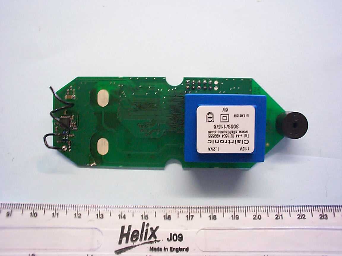
PM2201 P R O D U C T S T R U C T U R E S I N G L E L E V E L (P A R T S L I S T) R E P O R T P age 1 23/02/05 Avin Electronics Ltd From Part Number SME1001(1) to Part Number SME1001(1) Part Number Sort 00:07 Parent Number Description Type Issue Unit Quantity B Reference Date Eff' Date Eff' Date Of % Qty Seq' Component Nbr Description Typ /Msr Per F From To Change Loss Loss SME1001(1) Controller RF Issue 1 1 10033 3003/115/6 Transformer 1.2VA 115V 6V 4 EA 1.000 T1 21/01/05 99/99/99 21/01/05 .000 0 0021 AC101 Res 100R 0.1W 5% SMR63 4 EA 2.000 R4,22 08/10/04 99/99/99 21/01/05 .000 0 0002 AC102 Res 1K0 0.1W 5% SMR63 4 EA 1.000 R5 08/10/04 99/99/99 21/01/05 .000 0 0011 AC103 Res 10K 0.1W 5% SMR63 4 EA 3.000 R2,3,25 08/10/04 99/99/99 21/01/05 .000 0 0019 AC104 Res 100K 0.1W 5% SMR63 4 EA 1.000 R18 08/10/04 99/99/99 21/01/05 .000 0 0015 AC223 Res 22K 0.1W 5% SMR63 4 EA 1.000 R8 08/10/04 99/99/99 21/01/05 .000 0 0017 AC473 Res 47K 0.1W 5% SMR63 4 EA 2.000 R1,26 08/10/04 99/99/99 21/01/05 .000 0 0008 AC479 Res 4R7 0.1W 5% SMR63 4 EA 1.000 R6 08/10/04 99/99/99 21/01/05 .000 0 0025 BC847C Transistor NPN SOT23 4 EA 4.000 Q1-4 08/10/04 99/99/99 21/01/05 .000 0 0012 BR100 Fusable Res 10R 0.5W 350V 4 EA 1.000 FR1 08/10/04 99/99/99 21/01/05 .000 0 0037 FOILP1005(1)-B P1005 ISS.1 (TSL059) BOTT 4 EA 1.000 24/01/05 99/99/99 24/01/05 .000 0 0036 FOILP1005(1)-T P1005 ISS.1 (TSL058) TOP 4 EA 1.000 24/01/05 99/99/99 24/01/05 .000 0 0014 GA150 Cap. Ceramic 15pF 50V 5% 4 EA 2.000 C6,7 08/10/04 99/99/99 21/01/05 .000 0 0016 GA330 Cap. Ceramic 33pF 50V 5% 4 EA 3.000 C14,18,20 08/10/04 99/99/99 21/01/05 .000 0 0006 GA3R3 Cap.Ceramic 3.3pF50V 0603 4 EA 1.000 C19 08/10/04 99/99/99 21/01/05 .000 0 0007 GA3R9COG50 Cap.Ceramic 3p9F 50V 0603 4 EA 2.000 C15,16 08/10/04 99/99/99 21/01/05 .000 0 PM2201 P R O D U C T S T R U C T U R E S I N G L E L E V E L (P A R T S L I S T) R E P O R T P age 2 23/02/05 Avin Electronics Ltd From Part Number SME1001(1) to Part Number SME1001(1) Part Number Sort 00:07 Parent Number Description Type Issue Unit Quantity B Reference Date Eff' Date Eff' Date Of % Qty Seq' Component Nbr Description Typ /Msr Per F From To Change Loss Loss 0004 GB102 Cap.Ceramic 1nF 50V 10% 4 EA 2.000 C11,12 08/10/04 99/99/99 21/01/05 .000 0 0022 GB104Y5V 25V Cap.Cer 100nF 25V Y5V0603 4 EA 5.000 C2-5,8 17/11/04 99/99/99 21/01/05 .000 0 0005 GB105Y5V Cap.Cer 1uF 10V Y5V0603 4 EA 1.000 C10 08/10/04 99/99/99 21/01/05 .000 0 0009 GF475Y5V16 Cap 4u7F 16V 1206 20-80% 4 EA 1.000 C13 08/10/04 99/99/99 21/01/05 .000 0 0013 LQW18AN12NGOOD Inductor 12nH SMD 2% 4 EA 3.000 L1-3 08/10/04 99/99/99 21/01/05 .000 0 0035 M24C02-WMN6 E Squared S/M SO-8 4 EA 1.000 U5 09/11/04 99/99/99 21/01/05 .000 0 0018 M74HC595M1R 8-Shift Register 4 EA 1.000 U4 08/10/04 99/99/99 21/01/05 .000 0 0030 MB2S Bridge Rectifier0.5A 200V 4 EA 1.000 D1 10/10/04 99/99/99 21/01/05 .000 0 0003 NC102 Res Net 1Kx4 1206 .063W 4 EA 1.000 RP1 08/10/04 99/99/99 21/01/05 .000 0 0020 NC104 Res Net 100Kx4 1206 .063W 4 EA 1.000 RP2 08/10/04 99/99/99 21/01/05 .000 0 0024 NC221 Res Net 220Rx4 1206 .063W 4 EA 2.000 RP3,4 08/10/04 99/99/99 21/01/05 .000 0 0031 NRF905 RF Transceiver 32QFN5X5 4 EA 1.000 U1 10/10/04 99/99/99 21/01/05 .000 0 0010 NX3225DA160BLT Crystal 16MHz FA238 4 EA 1.000 Y1 08/10/04 99/99/99 21/01/05 .000 0 0001 PCBP1005(1) PCB CONTROLLER ISS.1(SME) 4 EA 1.000 21/01/05 99/99/99 21/01/05 .000 0 0032 ST72F264G2M6 Micro ST SMD 28pin SO28 4 EA 1.000 U3 10/10/04 99/99/99 21/01/05 .000 0 0027 TOL2012MGB LED Green SM0805 V/Mount 4 EA 7.000 D11,13,15,16,## 08/10/04 99/99/99 21/01/05 .000 0 D18-200028 TOL2012MRB LED Red SM0805 V/Mount 4 EA 7.000 D2,3,5,7,17,21# 10/10/04 99/99/99 21/01/05 .000 0 PM2201 P R O D U C T S T R U C T U R E S I N G L E L E V E L (P A R T S L I S T) R E P O R T P age 3 23/02/05 Avin Electronics Ltd From Part Number SME1001(1) to Part Number SME1001(1) Part Number Sort 00:07 Parent Number Description Type Issue Unit Quantity B Reference Date Eff' Date Eff' Date Of % Qty Seq' Component Nbr Description Typ /Msr Per F From To Change Loss Loss D220029 TOL2012MYB LED Yellow SM0805 V/Mount 4 EA 7.000 D4,6,8-10,12,14 10/10/04 99/99/99 21/01/05 .000 0 0026 TR12B Transducer 12mm External 4 EA 1.000 BZ1 08/10/04 99/99/99 21/01/05 .000 0 0023 VE1C101MF3R Cap 100uF 16V elec S/M 4 EA 1.000 C1 08/10/04 99/99/99 21/01/05 .000 0 0034 XC6201P332PR Voltage Regulator 3.3V 4 EA 1.000 U2 10/10/04 99/99/99 21/01/05 .000 0 ------------------------------------------------------------------------------------------------------------------------------- ----- 1 Items Selected Report Ends
Test Report
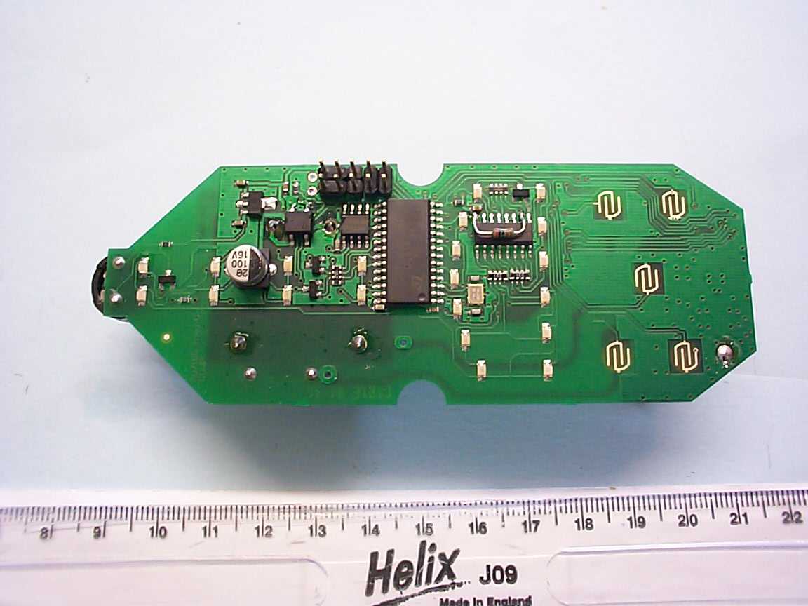
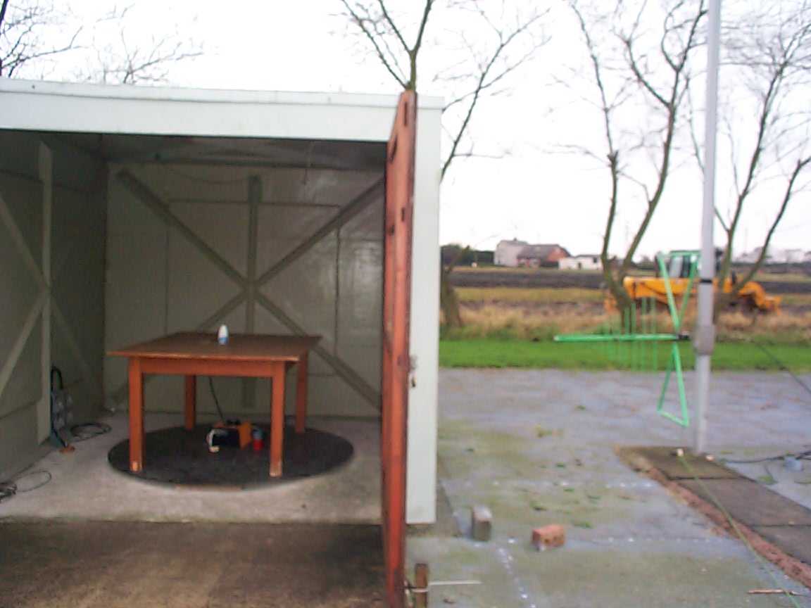
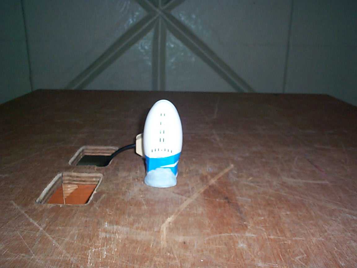
TRL COMPLIANCE SERVICES LTD EMC DIVISION M OSS VIEW NIPE LANE UP HOLLAND WEST LANCASHIRE WN8 9PY UNITED KINGDOM T ELEPHONE +44 (0)1695 556666 FAX +44 (0)1695 557077 E-MAIL [email protected] www.trlcompliance.com 0728 FS 21805 TEST REPORT NO: RU1142/6218 COPY NO: 2 ISSUE NO: 1 FCC ID: SSULD20D200 REPORT ON THE CERTIFICATION TESTING OF A SOLUTIONS MADE EASY Ltd LEAK TRACKER LD20-D REMOTE CONTROLLER WITH RESPECT TO THE FCC RULES CFR 47, PART 15.249 January 2005 INTENTIONAL RADIATOR SPECIFICATION TEST DATE: 14 th January 2005 – 3 rd February 2005 TESTED BY: D WINSTANLEY APPROVED BY: P GREEN EMC PRODUCT MANAGER DATE: 5 th December 2005 Distribution: Copy Nos: 1. SOLUTIONS MADE EASY Ltd 2. FCC EVALUATION LABORATORIES 3. TRL EMC THIS DOCUMENT MAY BE REPRODUCED ONLY IN ITS ENTIRETY AND WITHOUT CHANGE RF335U iss03 RU1142/6218 Page 2 of 28 CONTENTS PAGE CERTIFICATE OF CONFORMITY & COMPLIANCE 3 APPLICANT’S SUMMARY 4 EQUIPMENT TEST CONDITIONS 5 TESTS REQUIRED 5 TEST RESULTS 6-11 ANNEX PHOTOGRAPHS A PHOTOGRAPH No. 1: Radiated Test setup PHOTOGRAPH No. 2: Powerline Test setup PHOTOGRAPH No. 6: Transmitter front view PHOTOGRAPH No. 4: Transmitter rear view PHOTOGRAPH No. 5: Transmitter PCB track side PHOTOGRAPH No. 6: Transmitter PCB component side APPLICANT’S SUBMISSION OF DOCUMENTATION LIST B BAND OCCUPANCY PLOT C SCAN PLOT(s) D DUTY CYCLE PLOT(s) E Notes: 1. Component failure during test YES NO [ ] [X] 2. If Yes, details of failure: 3. The facilities used for the testing of the product contain in this report are FCC Listed. 4. The contents of the attached applicants declarations and other supplied information are not covered by the scope of this laboratory’s UKAS or FCC accreditations’ and is provided in good faith. RF335U iss03 RU1142/6218 Page 3 of 28 CERTIFICATE OF CONFORMITY & COMPLIANCE FCC IDENTITY: SSULD20D200 PURPOSE OF TEST: Certification TEST SPECIFICATION: FCC RULES CFR 47, Part 15.249 January 2005 TEST RESULT: Compliant to Specification EQUIPMENT UNDER TEST: LEAK TRACKER LD20-D REMOTE CONTROLLER EQUIPMENT SERIAL No: Engineering Sample EQUIPMENT TYPE: Interactive remote control & system status indicator PRODUCT USE: Leak detection system controller CARRIER EMISSION: 37.58 mV/m @ 3m ANTENNA TYPE: Integral ALTERNATIVE ANTENNA: Not applicable FREQUENCY OF OPERATION: 910.0MHz CHANNEL SPACING: Not applicable, Wideband NUMBER OF CHANNELS: Not Applicable FREQUENCY GENERATION: SAW Resonator [ ] Crystal [ ] Synthesiser [X] MODULATION METHOD: Amplitude [ ] Digital [X] Angle [ ] POWER SOURCE(s): +110Vac TEST DATE(s): 14 th January 2005 – 3 rd February 2005 ORDER No(s): 800015 APPLICANT: Solutions Made Easy Ltd ADDRESS: 261 Bath Road Bawdrip Somerset TA7 8PW TESTED BY: D WINSTANLEY APPROVED BY: P GREEN EMC PRODUCT MANAGER RF335U iss03 RU1142/6218 Page 4 of 28 APPLICANT’S SUMMARY EQUIPMENT UNDER TEST (EUT): LEAK TRACKER LD20-D REMOTE CONTROLLER EQUIPMENT TYPE: Interactive remote control & system status indicator SERIAL NUMBER OF EUT: Engineering Sample PURPOSE OF TEST: Certification TEST SPECIFICATION(s): FCC RULES CFR 47, Part 15.249 January 2005 TEST RESULT: COMPLIANT Yes No [X] [ ] APPLICANT’S CATEGORY: MANUFACTURER IMPORTER DISTRIBUTOR TEST HOUSE AGENT [X] [ ] [ ] [ ] [ ] APPLICANT’S ORDER No(s): 800015 APPLICANT’S CONTACT PERSON(s): Mr M Lee E-mail address: [email protected] APPLICANT: Solutions Made Easy Ltd ADDRESS: 261 Bath Road Bawdrip Somerset TA7 8PW TEL: +44 (0) 1278 686160 FAX: +44 (0) 1278 684077 EUT(s) COUNTRY OF ORIGIN: United Kingdom TEST LABORATORY: TRL EMC UKAS ACCREDITATION No: 0728 TEST DATE(s) 14 th January 2005 – 3 rd February 2005 TEST REPORT No: RU1142/6218 RF335U iss03 RU1142/6218 Page 5 of 28 EQUIPMENT TEST / EXAMINATIONS REQUIRED 1. TEST/EXAMINATION RULE PART DETECTOR APPLICABILITY Intentional Emission Frequency: 15.249(a) Quasi Peak YES Intentional Emission Field Strength: 15.249(a) Quasi Peak YES Intentional Emission Band Occupancy: 15.215 Peak YES Intentional Emission ERP (mW): N/A - NO Spurious Emissions – Conducted: 15.207 Quasi Peak Average YES Spurious Emissions – Radiated <1000MHz: 15.209 Quasi Peak YES Spurious Emissions – Radiated >1000MHz: 15.209 15.249(a) Average YES Maximum Frequency of Search: 15.33 - YES Antenna Arrangements Integral: 15.203 - YES Antenna Arrangements External Connector: 15.204 - YES Restricted Bands 15.205 - YES Extrapolation Factor 15.31(f) - YES 2. Product Use: Leak detection system controller 3. Emission Designator: 4. Duty Cycle: <100% 5. Transmitter bit or pulse rate and level: bps 6. Temperatures: Ambient (Tnom) 9 o C 7. Supply Voltages: Vnom +110Vac Note: Vnom voltages are as stated above unless otherwise shown on the test report page Single channel [X] Two channel [ ] 8. Equipment Category: Multi-channel [ ] Narrowband [ ] Wideband [X] 9. Channel spacing: RF335U iss03 RU1142/6218 Page 6 of 28 TRANSMITTER TESTS TRANSMITTER SPURIOUS EMISSIONS – RADIATED – PART 15.209 Ambient temperature = 8 o C(<1GHz) 3m measurements <1GHz [X] Relative humidity = 41% (<1GHz), 0.3m measurements >1GHz [X] Conditions = Open Area Test Site (OATS) 3m extrapolated from 0.3m [X] Supply voltage = +110Vac Channel number = 1 Freq (MHz) Meas Rx. (dBμV) Cable loss (dB) Ant Factor Field Strength (dBμV/m) Extrap Fact Field Strength (μV/m) Limit (μV/m) 30MHz - 88MHz 40.00 64.00 80.00 19.30 27.11 25.53 0.70 0.89 0.97 12.40 4.80 6.50 32.4 32.8 33.0 - 41.68 43.65 44.66 100 100 100 88MHz - 216MHz 160.00 168.00 176.00 25.09 24.11 23.45 1.41 1.44 1.46 9.30 8.95 8.60 35.8 34.5 33.6 - 61.66 53.08 47.86 150 150 150 216MHz - 960MHz 455.00 682.60 21.70 16.10 2.50 3.10 16.60 19.00 40.8 38.2 - 109.65 81.28 200 200 960MHz - 1GHz 1GHz - 5GHz 1.705MHz to 30MHz 30μV/m @ 30m 30MHz to 88MHz 100μV/m @ 3m 88MHz to 216MHz 150μV/m @ 3m 216MHz to 960MHz 200μV/m @ 3m 960MHz to 1GHz 500μV/m @ 3m Limits 1GHz to 5GHz 500μV/m @ 3m Notes: 1 Results quoted are extrapolated as indicated 2 Emissions were searched to: (x) 1000MHz inclusive, as per Part 15.33a 3 Extrapolation factor 20dB from 0.3m t…
Text truncated - open the document above for the full version.
Contact Information
Applicant
Michael Ernest Lee(Director)
Technical Contact
Solutions Made Easy LtdMike Lee
[email protected]+441278684984
261 Bath Rd · Bridgewater · United Kingdom
Test Firm
TRL Compliance LtdJohn Charters
Technical Specifications
| # | Rule Parts | Frequency Range | Power Output |
|---|---|---|---|
| 1 | 15C | 909.574 MHz - 910.286 MHz | - |
Other Applications from Solutions Made Easy Limited
SSULD20D100
Dec 14, 2005SME LD-20D Leak Tracker Shut off valve
Equipment Class
DXX - Part 15 Low Power Communication Device Transmitter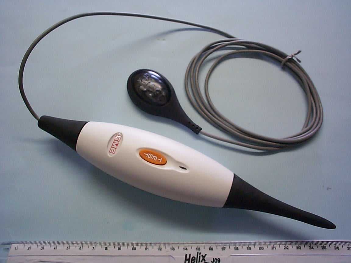
SSULD20D300
Dec 14, 2005SME LD20D Leak Tracker Wet Sensor
Equipment Class
DXX - Part 15 Low Power Communication Device Transmitter