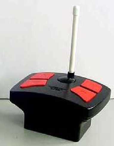
STF771020000DLControl Unit for RC Sumo Wrestler Toy
Dream Link Limited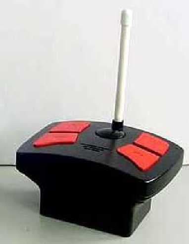
Click to zoom
Application Details
- Equipment Class
- DXX - Part 15 Low Power Communication Device Transmitter
- Date of Grant
- Sep 27, 2005
- Application Purpose
- Original Equipment
- Date of Application
- Sep 27, 2005
- Equipment Note
- Control Unit for RC Sumo Wrestler Toy
- Frequency Range
- 27.14500000 - 27.14500000
- Company
- Dream Link Limited
- Country
- Hong Kong
Documents & Files
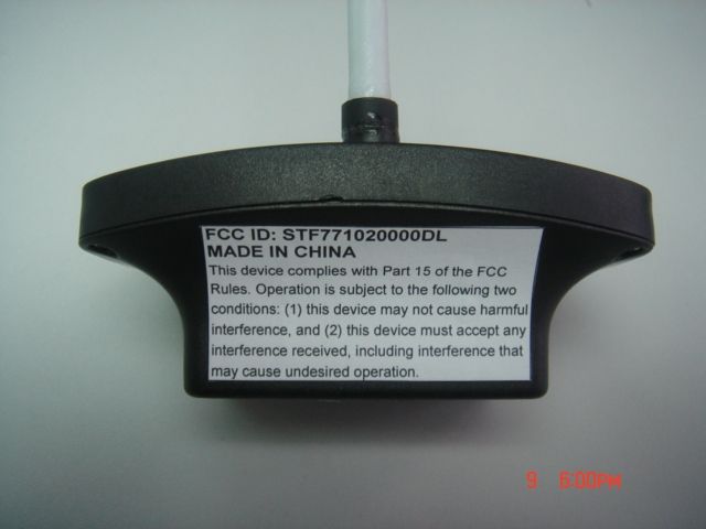
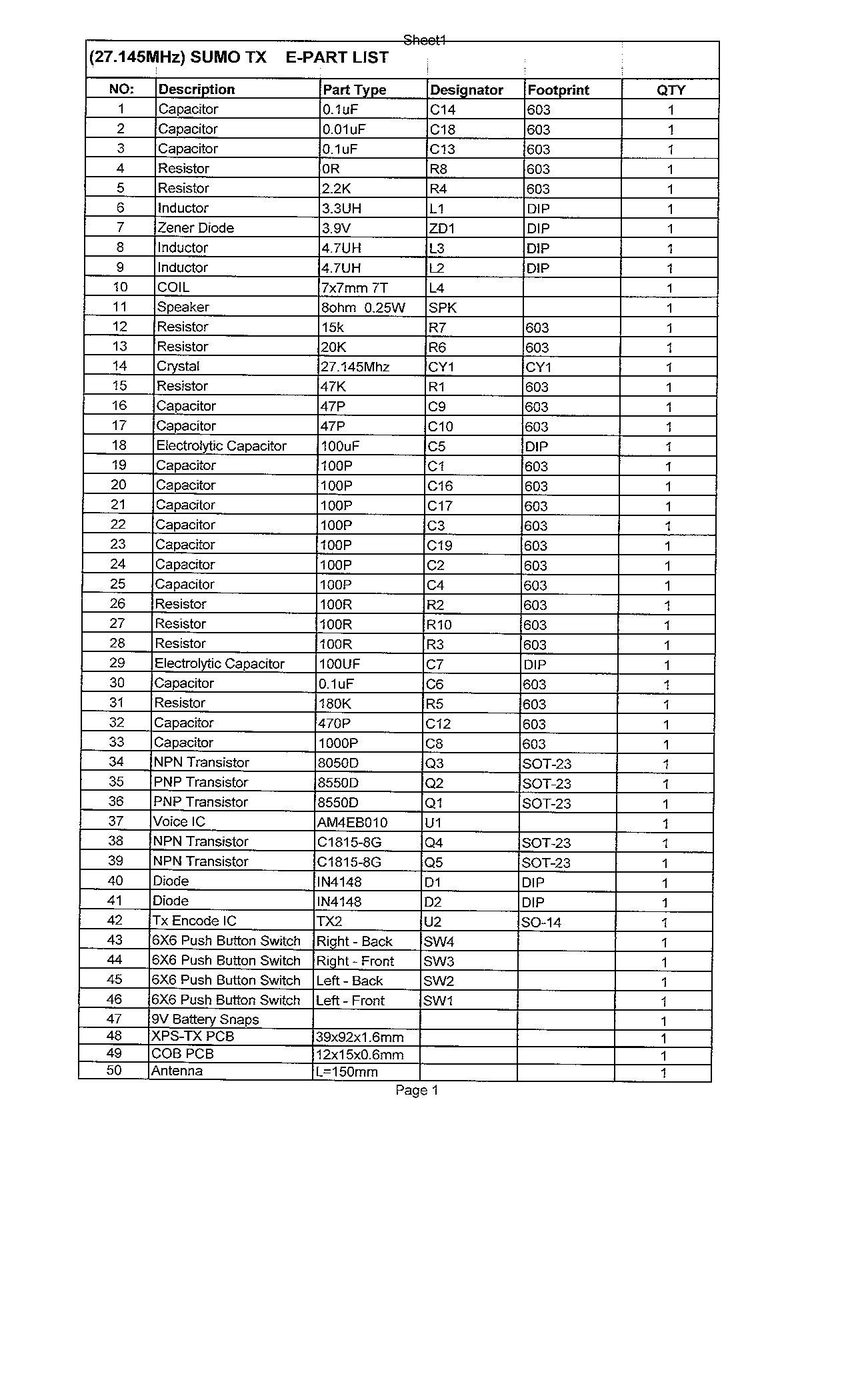
Document Text
Text extracted from the exhibit documents filed with the FCC. Open a document above to read the original.
Users Manual
INFLATABLE RC SUMO INSTRUCTION Movement: Rule: ForwardForward LeftForward Right Spinning or Backward Note: Use on different surfaces may effect the units performance. Blue Sumo Blue controller Red controller Base Inflatable Part Inflatable Part NOTE: These two pieces Sumo somtimes “POP OFF it’s base. It will easily POP Back ON. Red Sumo Battery installation: EastWest Dohyo Do not mix old and new batteries. Do not mix alkaline, standard (carbon zinc) or rechargeable (nickel-cadmium) batteries. Rechargeable batteries are not recommended. Due to small parts, batteries should be replaced by adult. Batteries must be inserted with correct polarity. Non-rechargeable batteries cannot be recharged. Only batteries of the same or equivalent type as recommended can be used. Exhausted batteries must be removed from the toy. The supply terminals must not be short-circuited. For best results use alkaline batteries. IMPORTANT BATTERY INFORMATION: WARNING : Changes or modifications to this unit not expressly approved by the party responsible for compliance could void the user's authority to operate the equipment. A bout is won by forcing the opponent out of the inner circle or by throwing him in the DOHYO. To lose the match it is not necessary to fall in the circle or to be pushed completely out. The rikishi who touches the ground with any part of his body, his knee or even the tip of his finger or his top-knot, loses the match. Or he need only put one toe or his heel over the straw bales marking the circle. The toeing-the-mark ritual that precedes the start of every bout in sumo. Shikiri ON OFF ON OFF Sumo Bottom Battery cover Battery cover Remote Control BottomRemote Control Bottom Use the screw driver, remove the battery box cover and fill 4 x 1.5V AA” R06 Batteries. Use the screw driver, remove the battery box cover and fill the 6F22 9V Battery. Attention: 1. Do not use vehicle in mud, water, snow, or sand. 2.Do not play with vehicle in the street. 3.Do not crash vehicle into any object at high speeds 4.When the vehicle slows down install new or freshly charged batteries. 5. Clean the vehicle with a damp paper towelafter operating.( Do not use any chemicals to wipe off car. 6.Do not leave vehicle in direct sunlight for lengthy periods. 7.Radio interfernce can cause your car to react strangely. 8.Another vehicle operating on the same frequency can disrupt your controlling the vehicle. 9.CB’s cellular telephones, two way radios, and other transmitting devices, and high tension wires may cause with operation. 10. Your vehicle can sometimes cause interference with television or even radio reception. Move to another area if you notice this occurrence. This device complies with Part 15 of the FCC Rules. Operation is subject to the following two conditions: (1) this device may not cause harmful interference, and (2) this device must accept any interference received, including interference that may cause undesired operation. Caution: To prevent bursting, do not use a high pressure pump such as an air compressor. Do not over inflate Battery cover Base Sumo BottomSumo Bottom
Cover Letter(s)
28 th September 2005. TRL Compliance Services Ltd; Long Green, Forthampton, Glos. For the attention of Mr P Harris, Dear Paul, RE: Dreamlink sumo wrestler 27.145MHz r/c product This is to confirm that when the above unit was tested by us (report No:P4285-1FCC) the switch was made and the unit was modulating. Regards Michael J Wood Technical & Managing Director
Internal Photos
Commercial - in - Confidence TEST REPORT REFERENCE EMC PROJECTS P4285-1/FCC Issue 1 PAGE 18 OF 20 FCC RULES CFR PART 15 TEST REPORT 12.4. Figure 8 Transmitter Circuit Board View 1
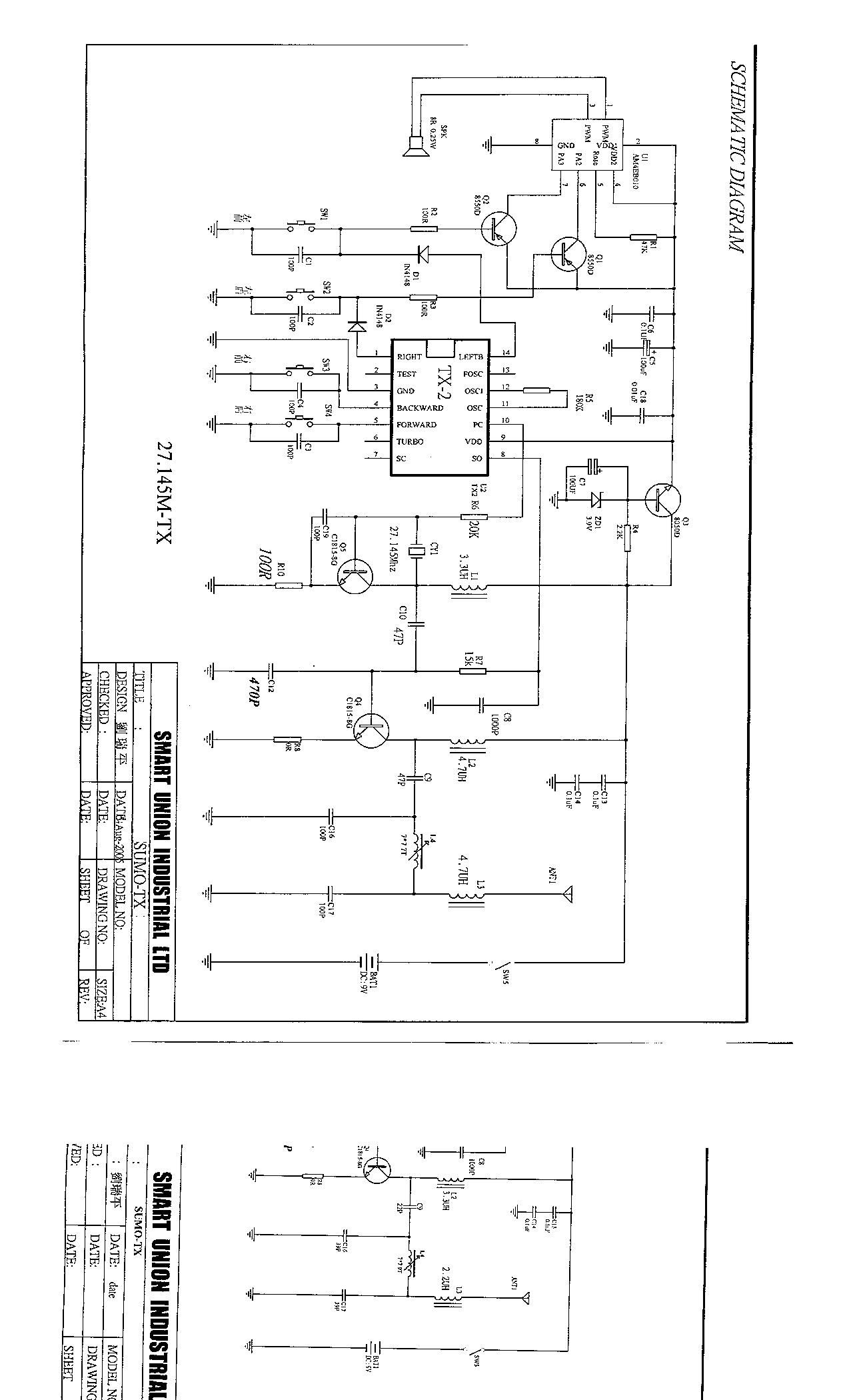
Operational Description
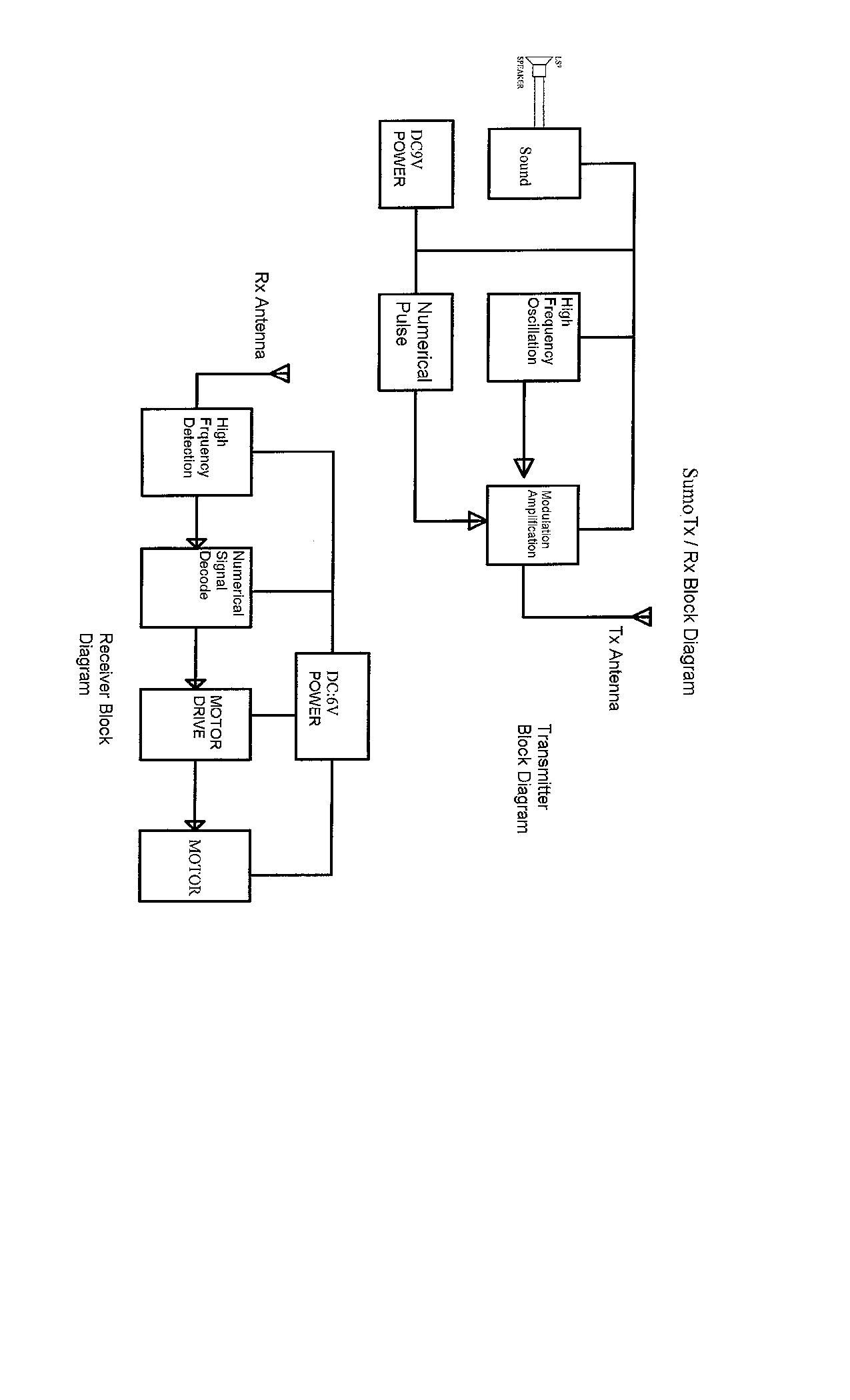
RC SUMO TX / RX Block Diagram Description 1) TX High frequency oscillation produces 27.145 MHZ OR 49.860 MHZ high frequency carrier wave. Then the carrier wave will mix with the numerical pulse and is amplified. Finally, the amplitude modulation carrier wave is transmitted though the TX antenna. At the same time, the speaker gives off sound. 2) RX Receive the 27.145 MHZ OR 49.860 MHZ amplitude modulation wave though the RX antenna. Then a carrier wave with same frequency is produced and detects the numerical pulse code. The IC will decode the numerical pulse code and transform to high radio frequency to drive the motor.
Test Report
Commercial In Confidence TEST REPORT No: P4285-1/FCC Issue 1 Customer/Applicant: Dream Link Ltd Address: Room 1207 Peninsula Centre 67 Mody Road Tsim Sha Tsui East Kowloon Hong Kong Subject: RADIO FREQUENCY DEVICES Customer Ref: Nixon Wu Manufacturer: Dream link Product: Radio Controlled Novelty Toys Model/Trade Name: Transmitter (27.145 MHz) Model No/Type: Sumo #771 Serial No - Tests Carried Out: FCC rules CFR 47 Part 15.109 Un-Intentional Radiator CFR 47 Part 15.227 Intentional Radiator (NUA) Date Of Test 12-15 th Aug 05 Location Ringwood This Report applies only to the above referenced EQUIPMENT and details the tests applied using test equipment calibrated to traceable National Standards and is not indicative of the qualities of identical or similar products Report Author: F Barkas Checked By: O.W.Cockram Title: (Planning Co-ordinator Radio) Title: (General Manager) Signature Signature Issue Date: Aug 2005 Tests marked “NUA” in this report are not included in the UKAS accreditation schedule for our laboratory. Opinions and interpretations expressed herein are outside the scope of UKAS accreditation. This Report is for the exclusive use of the Customer detailed and should not be reproduced except in full without written authority of EMC Projects Ltd. Page 1 of 20 Commercial In Confidence Commercial - in - Confidence TEST REPORT REFERENCE EMC PROJECTS P4285-1/FCC Issue 1 PAGE 2 OF 20 Report Summary Report Number : P4285-1/FCC Project Number: P4285 Test Dates : 12 – 15 th , Aug 2005 Test Engineer : Mr Frank Barkas In Attendance : - Product Use : Radio Control Model/Type Tested Sumo # 711 Operating Frequency 27.145 MHz Channel Spacing - Number of Channels 1 Antenna Type Integral Alternative Antenna Type - Power Supply 9v dc Battery Summary of Results: The equipment was assessed to the requirements of the following tests:- Rule Part Test Description Result / Class Pass/Fail Margin Levels/Comments Limits 15.227 Intentional Emission Frequency Pass 27.146625 MHz 26.96 – 27.28 MHz 15.227(e) Intentional Emission Field Strength Pass 38.16 dBμV/m 41.84 dB Below Limit 15.231(e) Spurious emissions transmitter operating – radiated Pass Maximum level 30.26 dBμV/ m 9.74 dB Below Limit 15.109 Unintentional Emitters Pass Maximum level 41.26 dBμV/ m 4.74 dB Below Limit 15.203 Antenna Arrangements Integral Pass - - 15.204 Antenna Arrangements External Connector N/A - - 15.205 Restricted Bands - - - 15.31(f) Extrapolation Factor - - 10.46dB For full details of pass level/criteria/class etc. see individual test results Table 1 Distribution:- Dream Link Ltd Copy No 1 EMC Projects Limited Copy No 2 TRL Compliance Services Copy No. 3 FCC RULES CFR PART 15 TEST REPORT FORM Commercial - in - Confidence TEST REPORT REFERENCE EMC PROJECTS P4285-1/FCC Issue 1 PAGE 3 of 20 CONTENTS Page 1. Applicants Summary/Declarations........................................................................................4 2. List Of Measurements...........................................................................................................4 3. Modes of operation............................................................................................................... 5 4. Test Setup.............................................................................................................................5 5. Deviations from Standard......................................................................................................5 6. Test Procedures....................................................................................................................5 7. Modification...........................................................................................................................5 8. Part 15.227 - Transmitter Intentional Emissions – Radiated.................................................6 8.1. Intentional Emission Frequency......................................................................................6 8.2. Intentional Emission Field Strength.................................................................................6 8.3. Test Method Part 15.227..........................................................................................6 8.4. Test Equipment Used:.....................................................................................................6 9. Part 15.227 - Transmitter Spurious Emissions – Radiated....................................................7 9.1. Transmitter Spurious Emissions <1000MHz...................................................................7 9.2. Test Method Part 15.227..........................................................................................7 9.3. Test Equipment Used:.....................................................................................................7 10. Part 15.109 - Ancillary Spurious Emissions – Radiated........................................................8 10.1. Spurious Emissions <1000MHz......................................................................................8 10.2. Test Method Part 15.109..........................................................................................8 10.3. Test Equipment Used:.....................................................................................................8 11. Graphs..................................................................................................................................9 11.1. Figure 1-Radiated Emissions -Transmitter On Fundamental........................................10 11.2. Figure 2-Radiated Emissions- Transmitter On Spurious...............................................11 11.3. Figure 3-Radiated Emissions –Transmitter & Ancillary Equipment Standby.................12 11.4. Figure 4-Radiated Emissions –Transmitter & Ancillary Equipment Operating..............13 12. Photographs........................................................................................................................15 12.1.…
Text truncated - open the document above for the full version.
Test Setup Photos
Commercial - in - Confidence TEST REPORT REFERENCE EMC PROJECTS P4285-1/FCC Issue 1 PAGE 15 of 20 12. Photographs All size were indicatored are in centimetre’s 12.1. Figure 5 Test Set Up OATS FCC RULES CFR PART 15 TEST REPORT
Contact Information
Applicant
Nixon Wu(Chief Operations Offcer)
Technical Contact
Dream Link LimitedNixon Wu
[email protected]852 2515 0832
Room 1207, Peninsula Centre · Kowloon · Hong Kong
Test Firm
EMC Projects Ltd.Michael Wood
Technical Specifications
| # | Rule Parts | Frequency Range | Power Output |
|---|---|---|---|
| 1 | 15C | 27.145 MHz - 27.145 MHz | - |
Other Applications from Dream Link Limited
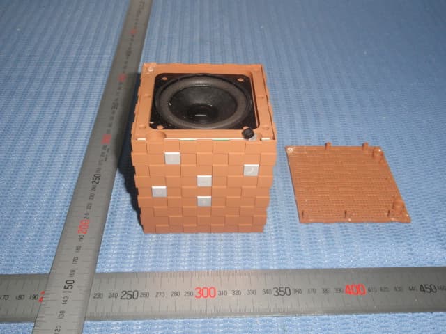
STFBS12
Nov 17, 2013Magic Cube Bluetooth Speaker
Equipment Class
DSS - Part 15 Spread Spectrum Transmitter
STF358
Jan 03, 2012iLauncher Thunder
Equipment Class
DSS - Part 15 Spread Spectrum Transmitter
STF056030000DL
Mar 12, 2008USB Radio Controlled Car
Equipment Class
DXX - Part 15 Low Power Communication Device Transmitter
STF771010000DL
Sep 27, 2005Control Unit for RC Sumo Wrestler Toy
Equipment Class
DXX - Part 15 Low Power Communication Device Transmitter