STQAIR00Stereo Audio Signal Transmitter over FM Band
Xtreme Accessories, LLC.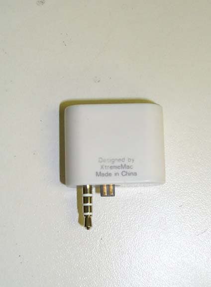
Click to zoom
Application Details
- Equipment Class
- DXX - Part 15 Low Power Communication Device Transmitter
- Date of Grant
- Jan 06, 2005
- Application Purpose
- Original Equipment
- Date of Application
- Jan 06, 2005
- Equipment Note
- Stereo Audio Signal Transmitter over FM Band
- Frequency Range
- 88.10000000 - 107.90000000
- Company
- Xtreme Accessories, LLC.
- Country
- United States
Documents & Files
Document Text
Text extracted from the exhibit documents filed with the FCC. Open a document above to read the original.
Users Manual
FCC ID: STQAIR00 Model: IA-AIR-00 Description: FM Transmitter Date: 30.Nov.2004 Introduction IA-AIR-00 is a stereo audio signal transmitter over FM band. It works as a slave device of iPOD and controlled by the digital command from iPOD through UART interface. It operates in either one of the two frequency bands. The two bands are hardware programmable by factory jumper setting of open and short. One is 88.1 to 107.9 MHz for U.S. The other one is 76.0 to 96.0 MHz for Japan. Both are in the step of 200 kHz. Features a. A LCD displays 4 digits in 7-segment format with one decimal place. Digits show the transmission frequency in the unit of MHz. b. Two buttons to adjust the transmission frequency. c. A DC power rates 3.3 Volts and 60mA whose is from the external device (No battery cell is needed or built-in). d. Stereo analog audio input is from external device. e. The operation mode of IA-AIR-00 is controlled by external device. FCC ID: STQAIR00 Description The ID appearance of IA-AIR-00 is shown in Figure 1 and 2. The functional block diagram of IA-AIR-00 is depicted in Figure 3. And the schematic is shown in Figure 4. The first stage is the transmitter plug-in iPOD and is tuned with the selected frequency. ID appearance The front of IA-AIR-00 has the said LCD and two control buttons. The LCD shows the transmission frequency in MHz with one decimal place and the display will switch off automatically for power saving purpose after no further key operation in 3sec. One of the control button symbolic “ —“ has the function of tuning the transmission frequency downward in 200kHz step. Another control button marked “ + ” tunes the frequency upward in 200kHz. At the bottom side of IA-AIR-00, there are two connectors. The audio plug is the audio signal input connector. And the dedicated 4 pins connector is the UART signal interface connection medium. On the top of IA-AIR-00, a customer logo is silk-screen printed. A brief product description is printed on the rear side of IA-AIR-00. Block diagram In the block diagram, there are totally six functional blocks, (1) Power management; (2) RF transmission; (3) Micro-controller unit; (4) Input device and interface; (5) Output device; (6) Memory. Schematic The key components of power management have REG710NA-5TI and MMBT3906. BH1415F is the key chips of RF transmission. EM78P806A is the essential part of IA-AIR-00 as the centralized control block. The dedicated firmware is resident inside the ROM part of the micro-controller. The control buttons are the input device. The interface is the audio signal input and the UART interface. The output device is LCD panel and the display backlight. HT2201 works as the memory of IA-AIR-00. It stores the transmission frequency and provides the last transmission frequency. FCC ID: STQAIR00 Appearance Figure 2 Figure 1 FCC ID: STQAIR00 Operation The default frequencies are 88.1MHz for US. Pressing the two buttons “ +” or “—” step the transmission frequency up or down respectively. Holding down the two buttons “ + ” or “—” for 3sec will accelerate the stepping frequency. IA-AIR-00 will turn on and start transmission for receiving the “Begin Transmission” command through UART interface or receiving audio signal through the audio plug for 3sec. System will turn off automatically for receiving the “End Transmission” command though UART interface or not receiving audio signal for 60sec. LCD of IA-AIR-00 will only be activated and turn on either system is plugged into iPOD or one of the control buttons is pressed. LCD will turn off automatically for no further activation in 8sec. The UART of IA-AIR-00 hires two pins, Rx and Tx, for interfacing to iPOD. The baud rate is either 9600bps or 19200bps. Communications use 8 data bits, no parity and one stop bit, i.e. 8-N-1. Upon power up of iPOD , IA-AIR-00 will wait 80msec and then send a “Sync” byte. Then will wait for another 20msec and send the “Identify” packet to identify itself to the iPOD. (See table 2.) Once the packet transmission has begun, the maximum time between transmitted characters must be less than 20msec. (See table 1 for packet format). The packet payload length is the number of bytes in the packet not including the “Sync” byte, packet start byte, packet payload length byte, or packet payload checksum bytes. That is, it is the length of the Command ID plus Lingo plus the Command data. Lingo ID for IA-AIR-00 is 0x05. IA-AIR-00 will send the packet shown in Table 2 at start up to identify itself and request power more than 5mA. Upon receipt of the begin transmission command (Table 3), system can begin drawing more than 5mA (up to 100mA). IA-AIR-00 will return to less than 5mA power usage within 1sec of receipt of an end transmission packet (Table 4). The iPOD may send a request to IA-AIR-00 to ask system to re-identify (Table 5). At this time system will send the identify packet to re-identify. The identify data payload is the command ID 0x01 followed by a single byte of the same values as the lingo specification of the functionality the device implements. The identify packet returned in response to a request identify packet does not need to have the extra sync bytes and delays used during the device startup process.
Cover Letter(s)
1 Helen Zhao To:Helen Zhao; 'Wei Li (E-mail)' Subject:RE: XtremeMac Associates, FCC ID: STQAIR00, Assessment NO.: AN05T4459, Notice#1 From: Weili Sent: Friday, January 07, 2005 1:12 PM To: Helen Zhao Subject: Re: FW: XtremeMac Associates, FCC ID: STQAIR00, Assessment NO.: AN05T4459, N... Hi, Helen. Here is the report and setup photo for re-testing. No big change. Your attention is appreciated. Best regards, Wei -----Original Message----- From: Compliance Certification Services [mailto:[email protected]] Sent: Thursday, January 06, 2005 1:44 PM To: Helen Zhao Subject: XtremeMac Associates, FCC ID: STQAIR00, Assessment NO.: AN05T4459, Notice#1 Question #1: FCC requests Bandwidth test with maximum input signal and user controls adjusted to maximize emission. The test report says "The system was configured for testing in a typical fashion (as a customer would normally use it)". Please provide detailed test setup diagram and the internal photos of the box the EUT was tested with. Please show how the audio input signal was added and how it was adjusted to the maximum emission. Answer: The max. audio input is provided by the circuit board specially designed for this test. That circuit board generated 1KHz audio signal for simulating the iPOD output. (Helen) It's not acceptable to test in this configuration since there is no way to verify whether the audio signal has been adjusted to the maximum emission and what kind of function the circuit board also has. Please test the device directly with iPOD, since this is the normal operation mode as described in the user manual. You can use a speaker as supporting equipment to make sure the audio signal has been maximized. Best Regards, Helen Zhao The items indicated above must be submitted before processing can continue on the above referenced application. Failure to provide the requested information within 30 days of the original e-mail date may result in application dismissal and forfeiture of the filing fee. 2 Also, please note that partial responses increase processing time and should not be submitted. Any questions about the content of this correspondence should be directed to the e-mail address listed below the name of the sender.
External Photos
FCC ID: STQAIR00 Advanced Compliance Lab, 6 Randolph Way, Hillsborough, NJ 08844 Tel: (908) 927-9288 Fax: (908) 927-0728 18 Front View FCC ID: STQAIR00 Advanced Compliance Lab, 6 Randolph Way, Hillsborough, NJ 08844 Tel: (908) 927-9288 Fax: (908) 927-0728 19 Rear View
ID Label/Location Info
FCC ID: STQAIR00 Advanced Compliance Lab, 6 Randolph Way, Hillsborough, NJ 08844 Tel: (908) 927-9288 Fax: (908) 927-0728 8 2. PRODUCT LABELING Figure 2.2 Location of Label on the Side of EUT Figure 2.1 FCC ID Label Figure 2.2 FCC ID Label Location FCC ID: STQAIR00 This device complies with part 15 of the FCC Rules. Operating is subject to the following two conditions: (1) This device may not cause harmful interference, and (2) this device must accept any interference received, including interference that may cause undesired operation. FCC Label
Internal Photos
FCC ID: STQAIR00 Advanced Compliance Lab, 6 Randolph Way, Hillsborough, NJ 08844 Tel: (908) 927-9288 Fax: (908) 927-0728 20 Open View FCC ID: STQAIR00 Advanced Compliance Lab, 6 Randolph Way, Hillsborough, NJ 08844 Tel: (908) 927-9288 Fax: (908) 927-0728 21 Component Side FCC ID: STQAIR00 Advanced Compliance Lab, 6 Randolph Way, Hillsborough, NJ 08844 Tel: (908) 927-9288 Fax: (908) 927-0728 22 Foil Side
Operational Description
FCC ID: STQAIR00 Operation The default frequencies are 88.1MHz for US. Pressing the two buttons “ +” or “—” step the transmission frequency up or down respectively. Holding down the two buttons “ + ” or “—” for 3sec will accelerate the stepping frequency. IA-AIR-00 will turn on and start transmission for receiving the “Begin Transmission” command through UART interface or receiving audio signal through the audio plug for 3sec. System will turn off automatically for receiving the “End Transmission” command though UART interface or not receiving audio signal for 60sec. LCD of IA-AIR-00 will only be activated and turn on either system is plugged into iPOD or one of the control buttons is pressed. LCD will turn off automatically for no further activation in 8sec. The UART of IA-AIR-00 hires two pins, Rx and Tx, for interfacing to iPOD. The baud rate is either 9600bps or 19200bps. Communications use 8 data bits, no parity and one stop bit, i.e. 8-N-1. Upon power up of iPOD , IA-AIR-00 will wait 80msec and then send a “Sync” byte. Then will wait for another 20msec and send the “Identify” packet to identify itself to the iPOD. (See table 2.) Once the packet transmission has begun, the maximum time between transmitted characters must be less than 20msec. (See table 1 for packet format). The packet payload length is the number of bytes in the packet not including the “Sync” byte, packet start byte, packet payload length byte, or packet payload checksum bytes. That is, it is the length of the Command ID plus Lingo plus the Command data. Lingo ID for IA-AIR-00 is 0x05. IA-AIR-00 will send the packet shown in Table 2 at start up to identify itself and request power more than 5mA. Upon receipt of the begin transmission command (Table 3), system can begin drawing more than 5mA (up to 100mA). IA-AIR-00 will return to less than 5mA power usage within 1sec of receipt of an end transmission packet (Table 4). The iPOD may send a request to IA-AIR-00 to ask system to re-identify (Table 5). At this time system will send the identify packet to re-identify. The identify data payload is the command ID 0x01 followed by a single byte of the same values as the lingo specification of the functionality the device implements. The identify packet returned in response to a request identify packet does not need to have the extra sync bytes and delays used during the device startup process.
Test Report
ELECTROMAGNETIC EMISSION COMPLIANCE REPORT of AIRPLAY FM TRANSMITTER MODEL: IA-AIR-00 FCC ID: STQAIR00 January 3, 2005 This report concerns (check one): Original grant x Class II change Equipment type: Low Power Intentional Radiator Deferred grant requested per 47 CF 0.457(d)(1)(ii)? yes no x If yes, defer until: (date) Company agrees to notify the Commission by (date) of the intended date of announcement of the product so that the grant can be issued on that date. Transition Rules Request per 15.37? yes no x If no, assumed Part 15, Subpart B for unintentional radiators - the new 47 CFR [10-1-90 Edition] provision. Report prepared for: XtremeMac Report prepared by: Advanced Compliance Lab Report number: 0048-041220-01 The test result in this report IS supported and covered by the NVLAP accreditation 6 Randolph Way Hillsborough, NJ 08844 Tel: (908) 927 9288 Fax: (908) 927 0728 Advanced Compliance Laboratory FCC ID: STQAIR00 Advanced Compliance Lab, 6 Randolph Way, Hillsborough, NJ 08844 Tel: (908) 927-9288 Fax: (908) 927-0728 2 Table of Contents Report Cover Page .........................................................................................................1 Table of Contents ...........................................................................................................2 Figures.............................................................................................................................3 1. GENERAL INFORMATION ...................................................................................4 1.1 Verification of Compliance .........................................................................4 1.2 Equipment Modifications............................................................................5 1.3 Product Information....................................................................................6 1.4 Test Methodology.........................................................................................6 1.5 Test Facility ..................................................................................................6 1.6 Test Equipment ............................................................................................6 1.7 Statement of the Document Use..................................................................7 2. PRODUCT LABELING............................................................................................8 3. SYSTEM TEST CONFIGURATION ......................................................................9 3.1 Justification ..................................................................................................9 3.2 Special Accessories.......................................................................................9 3.3 Configuration of Tested System .................................................................9 4. SYSTEM SCHEMATICS .........................................................................................12 5. RADIATED EMISSION DATA ...............................................................................13 5.1 Field Strength Calculation ..........................................................................13 5.2 Test Methods and Conditions .....................................................................13 5.3 Test Data .......................................................................................................14 5.4 Occupied Bandwidth ...................................................................................15 6. PHOTOS OF TESTED EUT ....................................................................................17 FCC ID: STQAIR00 Advanced Compliance Lab, 6 Randolph Way, Hillsborough, NJ 08844 Tel: (908) 927-9288 Fax: (908) 927-0728 3 Figures Figure 2.1 FCC ID Label..............................................................................................8 Figure 2.2 Location of Label on Back of the EUT ......................................................8 Figure 3.1 Radiated Test Setup, Position X.................................................................10 Figure 3.2 Radiated Test Setup, Position Y.................................................................10 Figure 3.3 Radiated Test Setup, Position Z .................................................................11 Figure 4.1 EUT Schematics ...........................................................................................12 Figure 5.1 Bandwidth Plot ............................................................................................15 Figure 6.1 Front View....................................................................................................18 Figure 6.2 Rear View .....................................................................................................19 Figure 6.3 Inside View, Cover Opened ........................................................................20 Figure 6.4 Component Side ...........................................................................................21 Figure 6.5 Foil Side ........................................................................................................22 FCC ID: STQAIR00 Advanced Compliance Lab, 6 Randolph Way, Hillsborough, NJ 08844 Tel: (908) 927-9288 Fax: (908) 927-0728 4 1. GENERAL INFORMATION 1.1 Verification of Compliance EUT: AIRPLAY FM TRANSMITTER Model: IA-AIR-00 Applicant: XtremeMac 15751 SW 41 Street, #100 Fort Lauderdale FL 33331 Test Type: FCC Part 15C CERTIFICATION Result: PASS Tested by: ADVANCED COMPLIANCE LABORATORY Test Date: January 3, 2005 Report Number: 0048-041220-01 The above equipment was tested by Compliance Laboratory, Advanced Technologies, Inc. for compliance with the requirement set forth in the FCC rules and regulations Part 15 subpart C. This said equipment in the configuration described in the report, shows the maximum emission levels emanating from equipment are within the compliance requirements. The estimated uncertainty of the test…
Text truncated - open the document above for the full version.
Contact Information
Applicant
Seth D. Lubin(Executive Vice President/Corporate Counsel)
Test Firm
Advanced Compliance LaboratoryWei Li
Technical Specifications
| # | Rule Parts | Frequency Range | Power Output |
|---|---|---|---|
| 1 | 15C | 88.1 MHz - 107.9 MHz | - |
Other Applications from Xtreme Accessories, LLC.
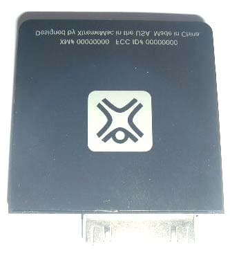
STQIPN00
Nov 02, 2005Airplay2 FM Transmitter IPN-APL-00/10
Equipment Class
DXX - Part 15 Low Power Communication Device Transmitter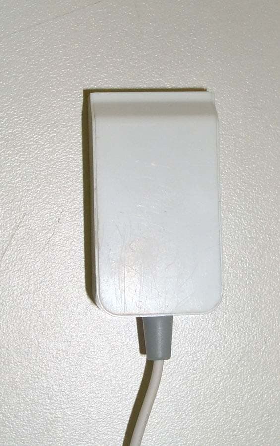
STQAPL00
Apr 25, 2005AirPlay for the iPoD Shuffle
Equipment Class
DXX - Part 15 Low Power Communication Device Transmitter