SU5-MSR-RTWAVEMSR Radio Module
VideoComm Technologies ( 1156488 Ontario Inc. )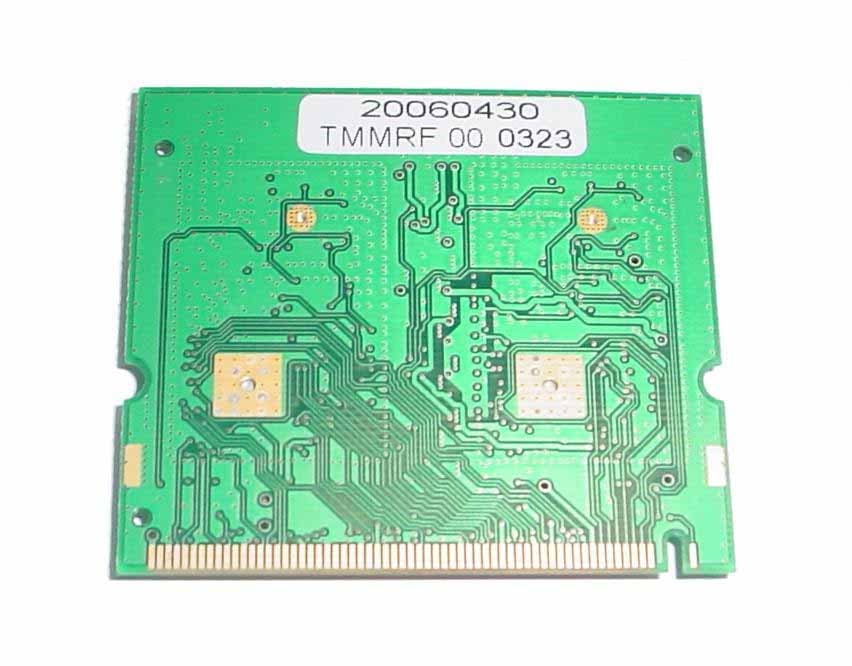
Click to zoom
Application Details
- Equipment Class
- DTS - Digital Transmission System
- Date of Grant
- Mar 25, 2008
- Application Purpose
- Original Equipment
- Date of Application
- Mar 25, 2008
- Equipment Note
- MSR Radio Module
- Frequency Range
- 5745.00000000 - 5805.00000000
- Country
- Canada
Documents & Files
Document Text
Text extracted from the exhibit documents filed with the FCC. Open a document above to read the original.
Users Manual
1 INSTALLATION MANUAL FOR THE MSR RADIO MODULE All Models Are Designed and Operate In A Point To-Point Configuration Only 2 FCC REGULATORY COMPLIANCE INTEGRATION AND USE INFORMATION INTEGRATION AND INSTALLATION REQUIREMENTS The MSR RADIO MODULE is designed exclusively for use in the VideoComm RTWave family of wireless video systems. The MSR RADIO MODULE will not function in any other system. However, there are certain criteria relative to integrating the radio into the RTWAVE system that must be considered to ensure continued compliance with FCC compliance requirements The MSR module was tested and certified to meet FCC Parts 15 in a stand-alone configuration. This demonstrates that the MSR module complies with Part 15 emission limits regardless of the system into which it may be installed. To simplify system integration of the same Radio Module into different systems and to help keep costs down on future systems using the same module, The MSR RADIO was FCC approved under the LIMITED MODULAR APPROVAL process for a radio transmitter. The Requirements as outlined in FCC Public Notice DA 00-131407 released June 26, 2000 are intended to afford relief to equipment manufacturers by eliminating the requirement for obtaining a new equipment authorization for the same transmitter when installed in a new device. This equipment has been tested and found to comply with the limits for a Class A digital device, pursuant to Part 15 of the FCC Rules. These limits are designed to provide reasonable protection against harmful interference when the equipment is operated in a commercial environment. This equipment generates, uses, and can radiate radio frequency energy and, if not installed and used in accordance with the instruction manual, may cause harmful interference to radio communications. Operation of this equipment in a residential area is likely to cause harmful interference in which case the user will be required to correct the interference at his own expense. VideoComm as the SYSTEM integrator of the module must follow all installation instructions and cautionary information necessary to comply with FCC RF exposure requirements. In order to use the MSR RADIO MODULE without additional FCC certification approvals, the installation must meet the following conditions. Otherwise, additional FCC approvals must be obtained. VideoComm specifies many SYSTEM models with different power levels and antenna gains. These are provided as part of this manual (see included exhibits for FCC test results) System Labeling will match the specific system as it is assembled. INDUSTRY CANADA REGULATORY COMPLIANCE INTEGRATION AND USE INFORMATION INTEGRATION AND INSTALLATION REQUIREMENTS This device has been designed to operate with the antennas listed herein and having a maximum gain of 32dB. Antennas not included in the list herein or having a gain greater than 32dB are strictly prohibited for use with this device. The required antenna impedance is 50Ohms Operation is subject to the following two conditions: (1) This device may not cause harmful interference, and (2) This device must accept any interference, including interference that may cause undesired operation of the device To reduce potential radio interference to other users, the antenna type and its gain should be so chosen that the equivalent isotropically radiated power (e.i.r.p.) is not more than that permitted for successful communication 3 Fixed and “mobile” applications 1. See Tables for models specific to the FIXED and MOBILE applications, ALL SYSTEMS ARE POINT TO POINT ONLY . This device has been designed to operate with the antennas listed below, and having a maximum gain of 32 dB. Antennas not included in this list or having a gain greater than 32 dB are strictly prohibited for use with this device. The required antenna impedance is 50 ohms OUTDOOR ALL WEATHER SYSTEMS ALL INSTALLED AS FIXED POINT TO POINT ONLY Rubber Duck Family 5.8 GHz SYSTEM MODEL AMPLIFIER PEAK POWER ANTENNA GAIN SEPARATION DISTANCE RT-L1R5803 NO 26.59 dBm 3dBi Ducky 20cm (7.9 Inches) RT-X1R5803 YES 29.04 dBm 3dBi Ducky 20cm (7.9 Inches) Antennas Tested By TCB Panel Antenna Family 5.8 GHz SYSTEM MODEL AMPLIFIER PEAK POWER ANTENNA GAIN SEPARATION DISTANCE RT-L1R5807 NO 26.59 dBm 7dBi Embedded 20cm (7.9 Inches) RT-X1R5807 YES 29.04 dBm 7dBi Embedded 20cm (7.9 Inches) RT-L1R5814 NO 26.59 dBm 14dBi Embedded 30.19 cm (11.9 Inches) RT-X1R5814 YES 29.04 dBm 14 dBi Embedded 40.03 cm (15.8 Inches) RT-L1R5821 NO 26.59 dBm 21 dBi External 67.59 cm (26.6 Inches) RT-X1R5821 YES 29.04 dBm 21dBi Embedded 89.62 cm (35.3 Inches) Antennas Tested By TCB Parabolic Antenna Family 5.8 GHz SYSTEM MODEL AMPLIFIER PEAK POWER ANTENNA GAIN SEPARATION DISTANCE RT-L1R5829 NO 26.59 dBm 29 dBi 169.79 cm (66.8 Inches) RT-X1R5829 YES 29.04 dBm 29 dBi 225.11 cm (88.6 Inches) RT-L1R5832 NO 26.59 dBm 32 dBi 239.83 cm (94.4 Inches) RT-X1R5832 YES 29.04 dBm 32 dBi 317.98 cm (125.2 Inches) Antennas Tested By TCB Rubber Duck ANTENNA FAMILY 2.4 GHZ SYSTEM MODEL AMPLIFIER PEAK POWER ANTENNA GAIN SEPARATION DISTANCE RT-L2R2403 NO 26.80 dBm 3dBi Ducky 20cm (7.9 Inches) PANEL ANTENNA FAMILY 2.4 GHZ SYSTEM MODEL AMPLIFIER PEAK POWER ANTENNA GAIN SEPARATION DISTANCE RT-WR2L245 NO 26.80 dBm 15 dBi 34.71 cm (13.7 Inches) Antennas Tested By TCB INDOOR DESKTOP SYSTEMS POINT TO POINT ONLY INDOOR DESKTOP SYSTEMS 5.8 GHz MOBILE APPLICATIONS POINT TO POINT ONLY SYSTEM MODEL RPS AMPLIFIER PEAK POWER ANTENNA GAIN SEPARATION DISTANCE XRT-L1R583 YES NO 26.59 dBm 3dBi Ducky 20cm (7.9 Inches) XRT-L1R588 YES NO 26.59 dBm 8 dBi Magnetic panel 20cm (7.9 Inches) XRT-X1R583 YES YES 29.04 dBm 3dBi Ducky 20cm (7.9 Inches) INDOOR DESKTOP FAMILY 2.4 GHZ MOBILE APPLICATIONS POINT TO POINT ONLY SYSTEM MODEL RPS AMPLIFIER PEAK POWER ANTENNA GAIN SEPARATION DISTANCE XRT-L2R243 YES NO 26.80 dBm 3 dBi Ducky 20cm (7.9 Inches) XRT-L2R248 YES NO 26.80 dBm 8 dBi Magnetic panel 20cm (7.9 Inches) (RPS= Reverse polarity SMA Connector) 4 2. If used with a desktop …
Text truncated - open the document above for the full version.
Users Manual
1 MSR RADIO External Amplifier The Amplifier portion of the EUT has the following Specifications: IC module is manufactured by Triquint Semiconductor. Description: The TGA2922-SG HPA provides 11dB of gain, 2 W of output power across 4.9 - 6 GHz and 2.5% EVM at 25 dBm output power. The device is ideally suited for high linearity, high power wireless data applications such as 802.11a WLAN Bridge Amplifiers, U-NII and Point to-Point or Point-to-Multi Point Non- Line of Sight radios. • 4.9-6.0 GHz frequency range • 11 db Gain (Nominal) (@8V 480 ma) • 34 dbm nominal P1dB @ 8V 480 ma • Bias Conditions 7-9 VDC @ 480 mA (Quiescent) Primary applications: • 802.11a WLAN bridge amplifier • U-NII Band HPA The amplifier power supply included with the system as tested with the EUT is included and manufactured by VideoComm. The Amplifier tested with the EUT is manufactured by VideoComm. 2 MSR RADIO External Amplifier Installation Instructions Follow installation of the main RTWAVE system with the following additions: 1. Install the heat sink plate assembly to the enclosure. Install heat sink to mounting plate on the outside the enclosure. 2. Attach the power supply to the inside mounting plate. 3. Attach the Amplifier PCB to the inside mounting plate. 4. Connect the MSR radio transmitter output to the Amplifier input connector using the supplied SMA connectors 5. Connect the Amplifier output connector to the transmitter antenna using the correct cable to match the included antenna. 6. Connect the receiver 7. Connect the power supply to the amplifier PCB (solder the connections) 8. Route the wires for the power supplies to the Amplifier power supply and System PCB’s. Connect the wires. 9. Attach the antenna (internal model or rubber ducks) (external or parabolic need not be connected 10. Send to test bench for software load, testing and conformity checks. Adjust as necessary. 11. Apply necessary labels to the system. 12. Send to shipping for packaging.
Users Manual
Advance Product Information April 27, 2005 1 TriQuint Semiconductor Texas Phone: (972)994-8465 Fax: (972)994 8504 Email: [email protected] Web: www.triquint.com 2 Watt 802.11a Packaged Amplifier TGA2922-SG Key Features •4.9 - 6 GHz Application Frequency Range •11 dB Nominal Gain @ 8V 480mA •34 dBm Nominal P1dB @ 8V 480mA •2.5% EVM at 25dBm output power •IMD3 -50dBc @ 22dBm SCL, Typical •Bias Conditions: 7-9 V @ 480 mA (Quiescent) •0.5 μm HFET Technology •2 lead Cu base SMT package Fixtured Measured Performance Bias Conditions: Vd = 8 V, Idq =480 mA Performance data taken @ in a 5.75GHz application circuit Primary Applications •802.11a WLAN Bridge Amplifiers •U-NII Band HPA •C-Band Pt-Pt and Pt-Multi Pt Radio The TGA2922-SG HPA provides 11dB of gain, 2 W of output power across 4.9 - 6 GHz and 2.5% EVM at 25 dBm output power. The device is ideally suited for high linearity, high power wireless data applications such as 802.11a WLAN Bridge Amplifiers, U-NII and Point- to-Point or Point-to-Multi Point Non- Line of Sight radios. The package has a high thermal conductivity copper base. Internal partial matching simplifies system board layout by requiring a minimum of external components. Lead-Free & RoHS compliant. Evaluation Boards are available. Product Description 0 4 8 12 16 20 24 28 32 36 40 9 1113151719212325272931 Pin (dBm) Pout (dBm) & Gain (dB) 300 400 500 600 700 800 IDS (mA) Pout IDS Gain -12 -9 -6 -3 0 3 6 9 12 15 44.555.566.57 Frequency (GHz) Gain (dB) -20 -15 -10 -5 0 5 10 15 20 25 Return Loss (dB) Gain Input Output Note: This device is early in the characterization process prior to finalizing all electrical specifications. Specifications are subject to change without notice. Advance Product Information April 27, 2005 2 TriQuint Semiconductor Texas Phone: (972)994-8465 Fax: (972)994 8504 Email: [email protected] Web: www.triquint.com TABLE I MAXIMUM RATINGS 1/ SymbolParameterValueNotes VdDrain Supply Voltage10 V2/ VgGate Supply Voltage Range0 V to -5 V IdqDrain Supply Current (Quiescent)1 A2/ | Ig |Gate Current19 mA P IN Input Continuous Wave Power30 dBm2/ P D Power Dissipation 4.1 W 2/, 3/ T CH Operating Channel Temperature175 ° C4/ T M Mounting Temperature (30 Seconds)260 ° C T STG Storage Temperature-65 to 150 ° C 1/ These ratings represent the maximum operable values for this device. 2/Combinations of supply voltage, supply current, input power, and output power shall not exceed P D . 3/When operated at this bias condition with a base plate temperature of 85 °C, the MTTF life is 2 E+8 hours. 4/ Junction operating temperature will directly affect the device median time to failure (T M ). For maximum life, it is recommended that junction temperatures be maintained at the lowest possible levels. TGA2922-SG Advance Product Information April 27, 2005 3 TriQuint Semiconductor Texas Phone: (972)994-8465 Fax: (972)994 8504 Email: [email protected] Web: www.triquint.com TABLE III THERMAL INFORMATION ParameterTest ConditionsT CH ( o C) R T JC ( q C/W) T M (HRS) R θ JC Thermal Resistance (channel to backside of package) Vd = 8 V I D = 480 mA (Quiescent) Pdiss = 3.8 W 168 224 E+8 Note: Package backside SnPb soldered to carrier at 85 ° C baseplate temperature. At saturated output power, the DC power consumption is 5.8 W with 2 W RF power delivered to the load. Power dissipated is 3.8 W and the temperature rise in the channel is 84 ° C. TABLE II RF CHARACTERIZATION TABLE (T A = 25qC, Nominal) (Vd = 8 V, Idq = 480 mA) SYMBOLPARAMETER TEST CONDITION TYPICALUNITS GainSmall Signal GainF = 5.75 GHz11dB IRLInput Return LossF = 5.75 GHz7dB ORLOutput Return LossF = 5.75 GHz7dB P1dBOutput Power @ P1dBF = 5.75 GHz34dBm TGA2922-SG Advance Product Information April 27, 2005 4 TriQuint Semiconductor Texas Phone: (972)994-8465 Fax: (972)994 8504 Email: [email protected] Web: www.triquint.com Bias Conditions: Vd = 7 V, Idq = 480 mA Measured Fixtured Data Application Circuit tuned to 5.75 GHz 10 15 20 25 30 35 40 45 50 55 60 65 1618202224262830 Output Power per tone (dBm) IMD3 (dBc) 5.6GHz 5.7GHz 5.8GHz 5.9GHz 6.0GHz 0 4 8 12 16 20 24 28 32 36 40 9 1113151719212325272931 Pin (dBm) Pout (dBm) & Gain (dB) 300 400 500 600 700 800 IDS (mA) Pout IDS Gain -12 -9 -6 -3 0 3 6 9 12 15 44.555.566.57 Frequency (GHz) Gain (dB) -20 -15 -10 -5 0 5 10 15 20 25 Return Loss (dB) Gain Input Output TGA2922-SG Advance Product Information April 27, 2005 5 TriQuint Semiconductor Texas Phone: (972)994-8465 Fax: (972)994 8504 Email: [email protected] Web: www.triquint.com Measured Fixtured Data Application Circuit tuned to 5.75 GHz Bias Conditions: Vd = 8 V, Idq = 480 mA 15 20 25 30 35 40 45 50 55 60 65 1618202224262830 Output Power per tone (dBm) IMD3 (dBc) 5.6GHz 5.7GHz 5.8GHz 5.9GHz 6.0GHz 0 4 8 12 16 20 24 28 32 36 40 9 1113151719212325272931 Pin (dBm) Pout (dBm) & Gain (dB) 300 400 500 600 700 800 IDS (mA) Pout IDS Gain -12 -9 -6 -3 0 3 6 9 12 15 44.555.566.57 Frequency (GHz) Gain (dB) -20 -15 -10 -5 0 5 10 15 20 25 Return Loss (dB) Gain Input Output TGA2922-SG Advance Product Information April 27, 2005 6 TriQuint Semiconductor Texas Phone: (972)994-8465 Fax: (972)994 8504 Email: [email protected] Web: www.triquint.com Bias Conditions: Vd = 8 V, Idq = 480 mA Measured Fixtured Data Application Circuit tuned to 5.75 GHz 15 20 25 30 35 40 45 50 55 60 65 1618202224262830 Output Power per tone (dBm) IMD3 (dBc) 5.6GHz 5.7GHz 5.8GHz 5.9GHz 6.0GHz 0 4 8 12 16 20 24 28 32 36 40 9 1113151719212325272931 Pin (dBm) Pout (dBm) & Gain (dB) 300 400 500 600 700 800 IDS (mA) Pout IDS Gain -12 -9 -6 -3 0 3 6 9 12 15 44.555.566.57 Frequency (GHz) Gain (dB) -20 -15 -10 -5 0 5 10 15 20 25 Return Loss (dB) Gain Input Outpu t TGA2922-SG Advance Product Information April 27, 2005 7 TriQuint Semiconductor Texas Phone: (972)994-8465 Fax: (972)994 8504 Email: [email protected] Web: www.triquint.com Bias Conditions: Vd = 8 V, Idq = 480 mA Measured Fixtured Data Application Circuit tuned to 5.75 GHz OFDM 64 QAM 0 1 2 3 4 5 6 7 8 9 14 15 16 17 18 19 20 21 22 2…
Text truncated - open the document above for the full version.
Attestation Statements
1 To: FCC Federal Communication Commission From: VideoComm Technologies Feb. 29, 2008 Re: Request for limited modular approval VideoComm Technologies of Oakville Ontario Canada are requesting FCC approval for their device “MSR RADIO MODULE” as a limited modular transmitter. The requirements of FCC Public Notice DA 00-1407 are met as follows: 1) The modular transmitter must have its own RF shielding. The MSR RADIO has all RF circuitry shielded. (See exhibit photos) 2) The modular transmitter must have buffered modulation data/inputs. The MSR RADIO has buffered modulation/data inputs. 3) The modular transmitter must have its own power supply regulation The MSR RADIO MODULE has its own power supply regulation. 4) The modular transmitter must comply with section 15.203 and 15.204(c) The MSR RADIO MODULE will be sold ONLY as part of a system made by VideoComm. As a module it complies with the antenna requirements. 5) The modular transmitter must be tested in a stand-alone configuration. The MSR RADIO MODULE was tested in a stand alone configuration 6) The modular transmitter must comply with the AC line conducted requirements found in Section 15.207. The MSR RADIO MODULE complies with AC LINE conducted requirements. 7) The modular transmitter must be labeled with its own FCC ID number. The MODULE will have the FCC ID affixed to it and the SYSTEM will also be labeled to indicate that “DEVICE CONTAINS MODULE with FCCID# “(see attached exhibits for diagrams and sample labels) 2 8) The modular transmitter must comply with any specific rule or operating requirements applicable to the transmitter and the manufacturer must provide adequate instructions with the module to explain any such requirements. The MSR RADIO MODULE complies with all applicable FCC Detailed instructions are given in the “Installation Guide” (see included exhibits) 9) The modular transmitter must comply with any applicable RF exposure requirements. The maximum measured power output is 801.68 mW (29.04 dBm), the maximum antenna gain is 32 dBi (highest gain antenna of all families tested) (see also FCC test report) The maximum permissible exposure is defined in 47 CFR 1.1310 with 1 mW/cm². The distance from the EUT's transmitting antenna where the exposure level reaches the maximum permitted level is calculated using the general equation: S EIRP S GP r ⋅⋅ = ⋅⋅ ⋅ = ππ44 (S Limit ) = 1.0 mW/cm 2 The tables below represent all of the system antennas. Those in “purple” were TCB tested. And the safe installation distances calculated It must be noted that these systems are manufactured, distributed and sold with the intention of Professional Installation of the final system. OUTDOOR ALL WEATHER SYSTEMS ALL INSTALLED AS FIXED POINT TO POINT ONLY Rubber Duck Family 5.8 GHz SYSTEM MODEL AMPLIFIER PEAK POWER ANTENNA GAIN SEPARATION DISTANCE RT-L1R5803 NO 26.59 dBm 3dBi Ducky 20cm (7.9 Inches) RT-X1R5803 YES 29.04 dBm 3dBi Ducky 20cm (7.9 Inches) Antennas Tested By TCB Panel Antenna Family 5.8 GHz SYSTEM MODEL AMPLIFIER PEAK POWER ANTENNA GAIN SEPARATION DISTANCE RT-L1R5807 NO 26.59 dBm 7dBi Embedded 20cm (7.9 Inches) RT-X1R5807 YES 29.04 dBm 7dBi Embedded 20cm (7.9 Inches) RT-L1R5814 NO 26.59 dBm 14dBi Embedded 30.19 cm (11.9 Inches) RT-X1R5814 YES 29.04 dBm 14 dBi Embedded 40.03 cm (15.8 Inches) RT-L1R5821 NO 26.59 dBm 21 dBi External 67.59 cm (26.6 Inches) RT-X1R5821 YES 29.04 dBm 21dBi Embedded 89.62 cm (35.3 Inches) Antennas Tested By TCB Parabolic Antenna Family 5.8 GHz SYSTEM MODEL AMPLIFIER PEAK POWER ANTENNA GAIN SEPARATION DISTANCE RT-L1R5829 NO 26.59 dBm 29 dBi 169.79 cm (66.8 Inches) RT-X1R5829 YES 29.04 dBm 29 dBi 225.11 cm (88.6 Inches) RT-L1R5832 NO 26.59 dBm 32 dBi 239.83 cm (94.4 Inches) RT-X1R5832 YES 29.04 dBm 32 dBi 317.98 cm (125.2 Inches) Antennas Tested By TCB Rubber Duck ANTENNA FAMILY 2.4 GHZ SYSTEM MODEL AMPLIFIER PEAK POWER ANTENNA GAIN SEPARATION DISTANCE RT-L2R2403 NO 26.80 dBm 3dBi Ducky 20cm (7.9 Inches) PANEL ANTENNA FAMILY 2.4 GHZ SYSTEM MODEL AMPLIFIER PEAK POWER ANTENNA GAIN SEPARATION DISTANCE RT-WR2L245 NO 26.80 dBm 15 dBi 34.71 cm (13.7 Inches) Antennas Tested By TCB Continued on the next page... 3 INDOOR DESKTOP SYSTEMS INDOOR DESKTOP SYSTEMS 5.8 GHz MOBILE APPLICATIONS POINT TO POINT ONLY SYSTEM MODEL RPS AMPLIFIER PEAK POWER ANTENNA GAIN SEPARATION DISTANCE XRT-L1R583 YES NO 26.59 dBm 3dBi Ducky 20cm (7.9 Inches) XRT-L1R588 YES NO 26.59 dBm 8 dBi Magnetic panel 20cm (7.9 Inches) XRT-X1R583 YES YES 29.04 dBm 3dBi Ducky 20cm (7.9 Inches) INDOOR DESKTOP FAMILY 2.4 GHZ MOBILE APPLICATIONS POINT TO POINT ONLY SYSTEM MODEL RPS AMPLIFIER PEAK POWER ANTENNA GAIN SEPARATION DISTANCE XRT-L2R243 YES NO 26.80 dBm 3 dBi Ducky 20cm (7.9 Inches) XRT-L2R248 YES NO 26.80 dBm 8 dBi Magnetic panel 20cm (7.9 Inches) (RPS= Reverse polarity SMA Connector) 5.8GHz Antenna Description & Manufacturer VCT Model # Supplier Part # Manufacturer Type Frequency Gain RUB-5803 GX5800X03J/w205 Wellhope Comm. Ducky 5.8GHz 3dBi RUB-5803rps GX5820Z15J/w281 Wellhope Comm. Ducky 5.8GHz 3dBi ANT-5807ip Not Applicable VideoComm Internal Patch 5.8GHz 7dBi ANT-5808ip-RPS Not Applicable VideoComm External Patch 5.8GHz 8dBi ANT-5814ip Not Applicable VideoComm Internal Patch 5.8GHz 14dBi ANT-5821dp Not Applicable VideoComm External Patch 5.8GHz 21dBi ANT-5821ip Not Applicable VideoComm Internal Patch 5.8GHz 21dBi PARA-5829 G5800P29A60 Guanhua Comm. Parabolic Dish 5.8GHz 29dBi PARA-5832 G5800P32A60 Guanhua Comm. Parabolic Dish 5.8GHz 32dBi Legend: RPS = Reverse Polarity SMA 2.4GHz Antenna Description & Manufacturer VCT Model # Supplier Part # Manufacturer Type Frequency Gain RUB-243s TLB-2400BL Boboto Telecom Ducky 2.4GHz 3dBi RUB-243RPS TLB-2400BLS Boboto Telecom Ducky 2.4GHz 3dBi ANT-2408ip/RPS HX5820Z08A/X951 Wellhope Comm. External Patch 2.4GHz 8dBi ANT-2415dp HX5820Z08A/X951 Wellhope Comm. Internal Patch 2.4GHz 15dBi RPS = Reverse Polarity SMA
Attestation Statements
Federal Communications Commission Authorization and Evaluation Division 1435 Oakland Mills Road Columbia, MD 21046 Date: March 11, 2008 SUBJECT: FCC Application for FCC ID: SU5-MSR-RTWAVE To Whom It May Concern: We, the undersigned, hereby attest to the fact that we will apply the Verification Authorization procedure to the Class A Unintentional Radiator portion of this composite filing. Regards, Jeff Johnson President VideoComm Technologies
Attestation Statements
To: FCC Federal Communication Commission From: VideoComm Technologies Feb. 29, 2008 Re: Notice of Professional Installation PROFESSIONAL INSTALLATION The MSR RADIO MODULE will be installed into its system only by VideoComm. The system once assembled will be knows as an RT Wave (family of products) The RT WAVE wireless system is designed and marketed for professional installation. This is ensured by VideoComm through the very nature of its marketing strategies and distribution network. All of VideoComm’s marketing and sales are directed to the professionals within the many industries we supply. These include Law enforcement, Government, Military, Industry, Manufacturing, Education and Industrial to name a few. VideoComm sells its products to Master Distributors and Dealers only. These dealers and distributors sell only to industry professionals who have experience in the installation of products like those manufactured by VideoComm. VideoComm’s distributors do not sell to the general public. These distributors are generally trade only. Please contact us if you have any additional questions. Best Regards Jeff Johnson President
Attestation Statements
3 Fixed and “mobile” applications 1. See Tables for models specific to the FIXED and MOBILE applications, ALL SYSTEMS ARE POINT TO POINT ONLY . This device has been designed to operate with the antennas listed below, and having a maximum gain of 32 dB. Antennas not included in this list or having a gain greater than 32 dB are strictly prohibited for use with this device. The required antenna impedance is 50 ohms OUTDOOR ALL WEATHER SYSTEMS ALL INSTALLED AS FIXED POINT TO POINT ONLY Rubber Duck Family 5.8 GHz SYSTEM MODEL AMPLIFIER PEAK POWER ANTENNA GAIN SEPARATION DISTANCE RT-L1R5803 NO 26.59 dBm 3dBi Ducky 20cm (7.9 Inches) RT-X1R5803 YES 29.04 dBm 3dBi Ducky 20cm (7.9 Inches) Antennas Tested By TCB Panel Antenna Family 5.8 GHz SYSTEM MODEL AMPLIFIER PEAK POWER ANTENNA GAIN SEPARATION DISTANCE RT-L1R5807 NO 26.59 dBm 7dBi Embedded 20cm (7.9 Inches) RT-X1R5807 YES 29.04 dBm 7dBi Embedded 20cm (7.9 Inches) RT-L1R5814 NO 26.59 dBm 14dBi Embedded 30.19 cm (11.9 Inches) RT-X1R5814 YES 29.04 dBm 14 dBi Embedded 40.03 cm (15.8 Inches) RT-L1R5821 NO 26.59 dBm 21 dBi External 67.59 cm (26.6 Inches) RT-X1R5821 YES 29.04 dBm 21dBi Embedded 89.62 cm (35.3 Inches) Antennas Tested By TCB Parabolic Antenna Family 5.8 GHz SYSTEM MODEL AMPLIFIER PEAK POWER ANTENNA GAIN SEPARATION DISTANCE RT-L1R5829 NO 26.59 dBm 29 dBi 169.79 cm (66.8 Inches) RT-X1R5829 YES 29.04 dBm 29 dBi 225.11 cm (88.6 Inches) RT-L1R5832 NO 26.59 dBm 32 dBi 239.83 cm (94.4 Inches) RT-X1R5832 YES 29.04 dBm 32 dBi 317.98 cm (125.2 Inches) Antennas Tested By TCB Rubber Duck ANTENNA FAMILY 2.4 GHZ SYSTEM MODEL AMPLIFIER PEAK POWER ANTENNA GAIN SEPARATION DISTANCE RT-L2R2403 NO 26.80 dBm 3dBi Ducky 20cm (7.9 Inches) PANEL ANTENNA FAMILY 2.4 GHZ SYSTEM MODEL AMPLIFIER PEAK POWER ANTENNA GAIN SEPARATION DISTANCE RT-WR2L245 NO 26.80 dBm 15 dBi 34.71 cm (13.7 Inches) Antennas Tested By TCB INDOOR DESKTOP SYSTEMS POINT TO POINT ONLY INDOOR DESKTOP SYSTEMS 5.8 GHz MOBILE APPLICATIONS POINT TO POINT ONLY SYSTEM MODEL RPS AMPLIFIER PEAK POWER ANTENNA GAIN SEPARATION DISTANCE XRT-L1R583 YES NO 26.59 dBm 3dBi Ducky 20cm (7.9 Inches) XRT-L1R588 YES NO 26.59 dBm 8 dBi Magnetic panel 20cm (7.9 Inches) XRT-X1R583 YES YES 29.04 dBm 3dBi Ducky 20cm (7.9 Inches) INDOOR DESKTOP FAMILY 2.4 GHZ MOBILE APPLICATIONS POINT TO POINT ONLY SYSTEM MODEL RPS AMPLIFIER PEAK POWER ANTENNA GAIN SEPARATION DISTANCE XRT-L2R243 YES NO 26.80 dBm 3 dBi Ducky 20cm (7.9 Inches) XRT-L2R248 YES NO 26.80 dBm 8 dBi Magnetic panel 20cm (7.9 Inches) (RPS= Reverse polarity SMA Connector)
Cover Letter(s)
March 14, 2008 Ultratech Engineering Labs Inc. 3000 Bristol Circle Oakville, ON Canada L6H 6G4 Subject: Application for Equipment Certification under FCC Part 15, Subpart C, Section 15.247 - Digital Modulation Systems (DTS) Operating in 2412-2462 MHz and 5745-5805 MHz Bands. Applicant: VideoComm Technologies (1156488 Ontario Inc.) Product: MSR Radio Module Model No.: MSR-RTWAVE FCC ID: SU5-MSR-RTWAVE Dear Sir/Madam As appointed agent for VideoComm Technologies (1156488 Ontario Inc.) we submit the application for certification of the above product. Please review all files uploaded to your electronic filing site NOTE: This application is subject to modular approval, see Applicant’s cover letter requesting for modular approval. This module required professional installation and may only be installed by the OEM or an OEM integrator. OEM integrators must be provided with antenna installation instructions and specific transmitter operating conditions for satisfying RF exposure compliance. Antenna(s) used for this transmitter must not be co-located or operating in conjunction with any other antenna or transmitter. In addition, the module was tested with and without external amplifier (the external amplifier is manufactured by VideoComm Technologies, model MSR-AMP, detailed specification can be found in this filing) for the operation in 5745-5805 MHz band and shall only be used in the configuration(s) of this filing. If you have any queries, please do not hesitate to contact us. Yours truly, Dan Huynh, B. Sc, Authorized Agent UltraTech Group of Labs Ultratech’s Accreditations: 0685 31040/SIT C-1376 46390-2049 200093-0 SL2-IN-E-1119R 3000 Bristol Circle, Oakville, Ontario, Canada L6H 6G4 Tel.: (905) 829-1570 Fax.: (905) 829-8050 Website: www.ultratech-labs.com Email: [email protected]
Cover Letter(s)
February 29, 2008 FEDERAL COMMUNICATIONS COMMISSION 7435 Oakland Mills Road Columbia, MD 21046 U.S.A. Subject: Authority to Act as an Agent to FCC Applicant: VideoComm Technologies (1156488 Ontario Inc.) Product: MSR RADIO MODULE Model: MSR-RTWAVE FCC ID: SU5-MSR-RTWAVE Dear Sir/Madam, I hereby appoint UltraTech Engineering Labs Inc. (UltraTech) to act as my agent in preparation of this application to F.C.C. for authorization of equipment under F.C.C. Rules. I also certify that the information provided, properly described the device or system for which authorization is required. Yours truly, Jeff Johnson
Cover Letter(s)
February 29, 2008 Federal Communications Commission Authorization and Evaluation Division Confidentiality Request regarding application for certification of: FCC ID: SU5-MSR-RTWAVE Pursuant to Sections 0.457 and 0.459 of the Commission’s Rules, we hereby request confidential treatment of information accompanying this application as outlined below: 1) Block Diagram 2) Schematics 3) Detailed Operational Description The above materials contain trade secrets and proprietary information not customarily released to the public. The public disclosure of these materials may be harmful to the applicant and provide unjustified benefits to its competitors. The applicant understands that pursuant to Section 0.457 of the Rules, disclosure of this application and all accompanying documentation will not be made before the date of the Grant for this application. Sincerely, Jeff Johnson President VideoComm Technologies [email protected]
ID Label/Location Info
Label for Module VIDEOCOMM TECHNOLOGIES MODEL: MSR-RTWAVE FCC ID: SU5-MSR-RTWAVE IC: 3667A-MSR VideoComm TechnologiesProduct Name: MSR RADIO MODULEModel: MSR-RTWAVE Contains FCC ID: SU5-MSR-RTWAVEContains IC: 3667A-MSROperation is subject to the following two conditions: (1) This device may not cause harmful interference, and (2) this devi ce must accept any in terference received, including interference that may cause undesired operation FCC & IC Label for Exterior Placement
RF Exposure Info
FCC Part 15, Subpart C, Section 15.247 – DTS Page 101 MSR Radio Module, Model MSR-RTWAVE FCC ID: SU5-MSR-RTWAVE ULTRATECH GROUP OF LABS File #: VCT-003F15C247 3000 Bristol Circle, Oakville, Ontario, Canada L6H 6G4 March 14, 2008 Tel. #: 905-829-1570, Fax. #: 905-829-8050, Email: [email protected] , Website: http://www.ultratech-labs.com All test results contained in this engineering test report are traceable to National Institute of Standards and Technology (NIST) 6.11. RF EXPOSURE REQUIRMENTS [§§ 15.247(e)(i), 1.1310 & 2.1091] The criteria listed in the following table shall be used to evaluate the environmental impact of human exposure to radio-frequency (RF) radiation. FCC 47 CFR § 1.1310: 6.11.1. Method of Measurements Refer to Sections 1.1310, 2.1091 In order to demonstrate compliance with MPE requirements (see Section 2.1091), the following information is typically needed: (1) Calculation that estimates the minimum separation distance (20 cm or more) between an antenna and persons required to satisfy power density limits defined for free space. (2) Antenna installation and device operating instructions for installers (professional/unskilled users), and the parties responsible for ensuring compliance with the RF exposure requirement (3) Any caution statements and/or warning labels that are necessary in order to comply with the exposure limits (4) Any other RF exposure related issues that may affect MPE compliance FCC Part 15, Subpart C, Section 15.247 – DTS Page 102 MSR Radio Module, Model MSR-RTWAVE FCC ID: SU5-MSR-RTWAVE ULTRATECH GROUP OF LABS File #: VCT-003F15C247 3000 Bristol Circle, Oakville, Ontario, Canada L6H 6G4 March 14, 2008 Tel. #: 905-829-1570, Fax. #: 905-829-8050, Email: [email protected] , Website: http://www.ultratech-labs.com All test results contained in this engineering test report are traceable to National Institute of Standards and Technology (NIST) Calculation Method of RF Safety Distance : 22 44r EIRP r GP S ⋅⋅ = ⋅⋅ ⋅ = ππ Where: P: power input to the antenna in mW EIRP: Equivalent (effective) isotropic radiated power S: power density mW/cm 2 G: numeric gain of antenna relative to iso…
Text truncated - open the document above for the full version.
Contact Information
Applicant
Jeff Peter Johnson(President)
Technical Contact
Ultratech Engineering Labs Inc.Dan Huynh
[email protected]905-829-1570
3000 Bristol Circle · Oakville, Ontario · Canada
Test Firm
UltraTech Engineering Labs Inc.Tri Luu
Technical Specifications
| # | Rule Parts | Frequency Range | Power Output |
|---|---|---|---|
| 4 | 15C | 5.75 GHz - 5.80 GHz | 456.00 mW |
Other Applications from VideoComm Technologies ( 1156488 Ontario Inc. )
SU5-TMX5808
Sep 24, 20065.8GHz Tx Module
Equipment Class
DXX - Part 15 Low Power Communication Device Transmitter
SU5-T5808
Mar 20, 20055.8GHz All Weather 8 Channel Series (Transmitter)
Equipment Class
DXX - Part 15 Low Power Communication Device Transmitter