SU5-T58085.8GHz All Weather 8 Channel Series (Transmitter)
VideoComm Technologies ( 1156488 Ontario Inc. )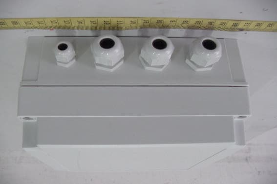
Click to zoom
Application Details
- Equipment Class
- DXX - Part 15 Low Power Communication Device Transmitter
- Date of Grant
- Mar 20, 2005
- Application Purpose
- Original Equipment
- Date of Application
- Mar 20, 2005
- Equipment Note
- 5.8GHz All Weather 8 Channel Series (Transmitter)
- Frequency Range
- 5733.00000000 - 5866.00000000
- Country
- Canada
Documents & Files
Document Text
Text extracted from the exhibit documents filed with the FCC. Open a document above to read the original.
Users Manual
5.8GHz All Weather 8 Channel Series OWNER’S MANUAL VideoComm Technologies –“The Freedom of Wireless” (888) 379-2666 US Toll Free (905) 339-0366 Phone (905) 339-1776 Fax www.VideoTransmitters.com [email protected] VideoComm Technologies TCO-5808 All Weather 8-Channel Series Video & Audio Connections –Receiver or Transmitter Loosen the desired cable gland using a Metric 22mm wrench. (Closest Imperial Size –7/8”) Feed the video and audio cable through the cable gland hole. VideoCommTechnologies recommends the use of RG-59 or higher grade coaxial cable for video and audio. Do not use video / audio cable that is less than ¼inch in diameter, as this may not allow a proper seal when the cable gland is tightened. If a tight seal is not made between the cable gland and the video cable, there is a chance of water leaking into the enclosure, causing serious damage. The maximum diameter of cable that should be used in the cable gland is ½an inch diameter. IMPORTANT!!!Attach BNC -male connectors to the video and audio cables afterthe raw cable has been fed through the cable gland. The BNC (M) connectors are to large to fit through the cable gland hole. Be careful not to damage the rubber seal inside the cable gland as you feed through your video cable. Attach BNC (M) connectors to the video and audio cables. After the BNC (M) connectors have been attached to the wire make terminations to video and audio bulkhead BNC (F) connectors for the device. WARNING!!! If you do not tighten the cable gland, you do not have a watertight seal. Using the three dipswitches select the desired channel frequency. Be sure to set the transmitter and receiver on the same channel. Please see dipswitch channel settings attached. NEGATIVE ( -) 9 –14VDC INPUT Inside the enclosure you will find a green terminal strip with orange terminal lock tabs. Push down the orange lock tabs to open the terminal input. Insert negative (-) and positive (+) wire leads as illustrated. Release the orange terminal lock tab. Ensure the wire is locked tight into the terminal to avoid an electrical short. POSITIVE (+) 9 –14VDC INPUT Power the transmitter and receiver to ONby sliding the ON / OFF switch to the down position. LED light will indicate power 5.8GHz 8 Channel Pin Settings 1 2 3 1 2 3 Channel # 2 Pin # 1 Up Pin # 2, 3 Down Channel # 1 Pin # 1, 2, 3 Down 1 2 3 1 2 3 Channel # 3 Pin # 2 Up Pin # 1, 3 Down Channel # 4 Pin # 1, 2 Up Pin # 3 Down 1 2 3 1 2 3 Channel # 6 Pin # 1, 3 Up Pin # 2 Down Channel # 5 Pin # 3 Up Pin # 1, 2 Down 1 2 3 1 2 3 Channel # 7 Pin # 2, 3 Up Pin # 1 Down Channel # 8 Pin # 1, 2, 3 Up VideoComm Technologies TCO-5808 All Weather 8-Channel Series Bus (905)-339-0366 US Toll Free 888-379-2666 Fax (905)-339-1776 E-mail - - - [email protected] [email protected] Web Site www.VideoTransmitters.com Monday -Friday 8:30am- 5:30pm Eastern Standard Time I.THIS DEVICE COMPLIES WITH FCC RULES PART 15. OPERATION IS SUBJECT TO THE FOLLOWING TWO CONDITONS: 1. This device may not cause harmful interference, and 2. This device must accept any interference received, including that causing undesired operation. II. In order to comply with the FCC/IC adopted RF exposure requirements, this transmission system will be installed by an authorized professional installer of VideoComm Technologies. III.This is NOT an intrinsically safe device. Do not take into areawhere intrinsic safety is required. Bodily harm may result if warning is ignored. IV.DO NOT OPERATE TRANSMITTER WITHOUT ANTENNA CONNECTED TO ANTENNA PORT. Failure to do so will result in damage to the unit and void the warranty. V.DO NOT OPERATE THE TCO-5800 SYSTEM WHEN the Transmitter & Receiver are closer than ten feet to each other. The devices may not work properly and permanent damage can occur. The term “IC:”before the radio certification number only signifies that Industry Canada Technical specifications were met. Operation is subject to the following two conditions: (1) this device may not cause interference, and (2) this device must accept any interference, including interference that may cause undesired operation of the device.
Users Manual
5.8GHz All Weather 8 Channel Series Manual Rev. E 5.8GHz All Weather 8 Channel Series OWNER’S MANUAL VideoComm Technologies – “The Freedom of Wireless” (888) 379-2666 US Toll Free (905) 339-0366 Phone (905) 339-1776 Fax http://www.videotransmitters.com/ [email protected] 5.8GHz All Weather 8 Channel Series Manual Rev. E SAFETY NOTICES NOTE: This equipment has been tested and found to comply with the limits for a Class B digital device, pursuant to Part 15 of the FCC Rules. These limits are designed to provide reasonable protection against harmful interference in a residential installation. This equipment generates, uses and can radiate radio frequency energy and, if not installed and used in accordance with the instructions, may cause harmful interference to radio communications. However, there is no guarantee that interference will not occur in a particular installation. If this equipment does cause harmful interference to radio or television reception, which can be determined by turning the equipment off and on, the user is encouraged to try to correct the interference by one or more of the following measures: * Reorient or relocate the receiving antenna. * Increase the separation between the equipment and receiver. * Connect the equipment into an outlet on a circuit different from that to which the receiver is connected. * Consult the dealer or an experienced radio/TV technician for help. 5.8GHz All Weather 8 Channel Series Manual Rev. E Tools Required The 5.8GHz All Weather 8 Channel Series is designed to be “Plug & Play” and simple to install with minimal tools. The following is a list of recommended tools to setup your system. Coaxial Cable Stripper - For preparing video & audio coaxial cable. Wire Stripper – For preparing alarm input and power wires. Phillips Screw Driver – Used for unscrewing the front cover of the IP-67 enclosure to gain access to video, audio, alarm input and power terminations. Mini Flat Head (Slot) Screw Driver – Used for changing the receiver antennas polarization from horizontal to vertical. ( if required ) Metric 22mm Wrench ( Closest Imperial Size – 7/8”) - Used for tightening or loosening the three larger all weather cable glands. Do not use pliers as they may cause damage to the cable glands Metric 15mm Wrench (Closest Imperial Size – 5/8”) – - Used for tightening or loosening the single small all weather cable gland. Do not use pliers as they may cause damage to the cable glands Hand Held LCD Monitor – Recommended for verifying video images at input to transmitter and output from receiver. Perfect for camera angle and focus adjustment. Multimeter – Measures voltage output, amperage, resistance and cable continuity. Do Not Use Pliers - the pliers rigid grip may cause damage to the cable glands and the all weather IP-67 enclosure. 5.8GHz All Weather 8 Channel Series Manual Rev. E Opening & Closing The All Weather Enclosure To make all video, audio, alarm input and power terminations we must access the interior of the enclosure by removing the front cover. . . The front cover can be removed two ways: 1. Loosen screws using the thumb tab screw covers. - OR - Use a Phillips or flat head (slot) screwdriver to loosen the screws. WARNING!!! When closing the enclosure do not over-tighten. 5.8GHz All Weather 8 Channel Series Manual Rev. E Video& Audio Cable Installation & Termination Loosen the desired cable gland using a Metric 22mm wrench. (Closest Imperial Size – 7/8”) Feed the video and audio cable through the cable gland hole. VideoComm Technologies recommends the use of RG-59 or higher grade coaxial cable for video and audio. Do not use video / audio cable that is less than ¼ inch in diameter, as this may not allow a proper seal when the cable gland is tightened. If a tight seal is not made between the cable gland and the video cable, there is a chance of water leaking into the enclosure, causing serious damage. The maximum diameter of cable that should be used in the cable gland is ½ an inch diameter. IMPORTANT!!! Attach BNC - male connectors to the video and audio cables after the raw cable has been fed through the cable gland. The BNC (M) connectors are to large to fit through the cable gland hole. Be careful not to damage the rubber seal inside the cable gland as you feed through your video cable. Attach BNC (M) connectors to the video and audio cables. After the BNC (M) connectors have been attached to the wire make terminations to video and audio bulkhead BNC (F) connectors for the device. WARNING!!! If you do not tighten the cable gland, you do not have a watertight seal. 5.8GHz All Weather 8 Channel Series Manual Rev. E Unused Grommet Seals After video and audio cables are installed and terminated you may find there one or more cable glands are not being used. If there are cable glands not being used this means that water can enter the enclosure, causing damage. To prevent this from happening, VideoComm includes black plugs to seal off any unused cable glands. Turn cable gland counter clock wise to loosen. Use a Metric 22mm wrench. (Closest Imperial Size – 7/8”) From the inside of the enclosure, insert black plugs into unused cable glands. Using a Metric 22mm wrench (Closest Imperial Size – 7/8”), turn the cable gland clock wise to tighten; this will make a watertight seal. Do not over tighten. IMPORTANT! Failure to tighten the cable gland may result in water 5.8GHz All Weather 8 Channel Series Manual Rev. E damage, not covered under manufacturer warranty. Power Supply Connection Inside the enclosure you will find a green terminal strip with orange terminal lock tabs. WARNING! Transformer must not be powered while making connections to the terminal strip. An electrical short can occur, causing harmful damage to the unit. Turn the small cable gland counter clock wise to loosen. Use a Metric 15mm wrench. (Closest Imperial Size – 5/8”) Feed the power cable wire through the cable gland hole. Push down the orange lock tabs to open the terminal …
Text truncated - open the document above for the full version.
Cover Letter(s)
Federal Communications Commission FCC ID: SU5-T5808 Dear Sir: In accordance with 47 C.F.R. Section 0.459, we would like to request confidentiality on some exhibits we submitted for above original application for the reason of trade secret. If those exhibits are available for public inspection, any person who once gets the information contained in those exhibits will be able to design and to make the same products very easily. This is a very serious problem and huge loss for us, because we did invest so much on it. Please be not made the Exhibit Types listed below routinely available for public inspection: Block Diagram and Schematics. By: By: Jeff Johnson (Signature) (Printed) Title : Director Applicant : 1156488 Ontario Inc. O/A VideoComm Technologies Address : 204-407 Speers Road, Oakville, Ontario, Canada L6K 3T5 Tel : 905-339-0366 Fax: 905-339-1776 Date : January 30 th , 2005
Cover Letter(s)
Federal Communications Commission Dear Sir: We, the undersigned, hereby authorize ELECTRONICS TESTING CENTER, TAIWAN to act on our behalf in all matters relating to application for Model : TCO-5808, FCC ID : SU5-T5808 authorization, including the signing of all documents relating to these matters. Any and all acts carried out by ELECTRONICS TESTING CENTER, TAIWAN on our behalf shall have the same effect as acts of our own. The applicant certifies that in the case of an individual applicant ( e.g., corporation ), no party to the applicant is subject to a denial of federal benefits, that includes FCC benefits, pursuant to section 5301 of the Anti-drug abuse Act of 1988, 21 U.S.C. 862. For a definition of a “party” for these purposes See 47 C.F.R. 1.2002(b). By: By: Jeff Johnson (Signature) (Printed) Title : Director Applicant : 1156488 Ontario Inc. O/A VideoComm Technologies Address : 204-407 Speers Road, Oakville, Ontario, Canada L6K 3T5 Tel : 905-339-0366 Fax: 905-339-1776 Date : January 30 th , 2005
Cover Letter(s)
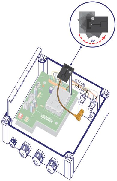
Helen Zhao Subject: FW: VideoComm Technologies (1156488 Ontario Inc.), FCC ID: SU5-T5808, Assessment NO.: AN05T4612, Notice#1 3/21/2005 -----Original Message----- From: SS Sent: Monday, March 21 , 2005 9:53 PM To: Helen Zhao Cc: R00/??? Subject: Re: VideoComm Technologies (1156488 Ontario Inc.), FCC ID: SU5-T5808, Assessment NO.: AN05T4612, Notice#1 Dear Helen, #3 Please refer to revised test report. Two antenna polarization has been tested. #4 Here is the explain from the applicant: The final production model will have a reverse-polarity SMA that will not be removable. It will be locked to the metal strain relief plate where the cable feed from the RF module is also attached. The metal strain relief plate is the same part that has the BNC-female connectors attached. The antenna for the transmitter is called a # ANT-5803IP and has 3dBi gain and is also directional - I am sorry but I do not have any pictures of the radiating pattern for the transmitter antenna. see the jpg picture 58_txAnt.jpg for view of transmitter antenna inside the enclosure. #5 & #6 Please see revised user manual. Best regards, S. S. Liou Dear SS, Mike and I looked at this installation guide and manual, below are the questions: Question #3: The installation guide indicates that Antenna Polarization is changable. Please advise the antenna was in horizontal or vertical polarization during the test. You may need to investigate two situations. Question #4: Please provide antenna specification including connector or cable information. Question #5: The RF exposure statement in the user manual said, "Installation of all antennas must be performed in a manner that will provide at least 23cm clearance from the front radiating aperture, to any user or member of the public." This is not necessary to a 15.249 device. You can remove this from the manual, the FCC grant will only indicate professional installation, but won't limit the separation distance. Question #6: The user manual said: "The system has been certified by the FCC for use with other products without any further certification (as per FCC section 2.1091.) " This device is not obtaining modular approval, this wording is not applicable. Please remove this from the user manual. Best Regards, Helen Dear Helen, Please find attached installation guide. Regards, S. S. Liou Question #1: Confidentiality requests must reference Section 0.459 at a minimum because this section provides the authority for such a request. Referencing Section 0.457 is not mandatory but it is suggested because this section lists what information is normally held confidential in equipment authorization filings. Please revise your confidentiality letter accordingly. Question #2: The user manual in the filing does not contain enough instruction as how to install and operate the EUT, it does not even explain what the four ports are connected with, and what is the normal placement of the device (lying on the table, or sitting on the table as show in the setup photos, the four ports up or down). Please explain function of the port that was not connected during the test and why. 3/21/2005
External Photos
ETC Report No. : ET94R-01-019-01 Sheet 1 of 6 Sheets FCC ID.: SU5-T5808 Rev. No 2.0 CONSTRUCTED PHOTOS of EUT 1. Top View of EUT 2. Bottom View of EUT ETC Report No. : ET94R-01-019-01 Sheet 2 of 6 Sheets FCC ID.: SU5-T5808 Rev. No 2.0 CONSTRUCTED PHOTOS of EUT 3. Side View of EUT 4. Front View of EUT ETC Report No. : ET94R-01-019-01 Sheet 3 of 6 Sheets FCC ID.: SU5-T5808 Rev. No 2.0 CONSTRUCTED PHOTOS of EUT 5. Side View of EUT 6. Rear View of EUT
ID Label/Location Info
undesired operation. Including interference that may cause accept any interference received. interference and 2) This device must device may not cause harmful the following two conditions : 1)This the FCC rules. Operation is subject to FCC ID : This device complies with part 15 of Made in Canada
Internal Photos
ETC Report No. : ET94R-01-019-01 Sheet 4 of 6 Sheets FCC ID.: SU5-T5808 Rev. No 2.0 CONSTRUCTED PHOTOS of EUT 7. Internal View of EUT 8. Internal View of EUT ETC Report No. : ET94R-01-019-01 Sheet 5 of 6 Sheets FCC ID.: SU5-T5808 Rev. No 2.0 CONSTRUCTED PHOTOS of EUT 9. Component View of PCB 10. Solder View of PCB ETC Report No. : ET94R-01-019-01 Sheet 6 of 6 Sheets FCC ID.: SU5-T5808 Rev. No 2.0 CONSTRUCTED PHOTOS of EUT 11. Component View of PCB 12. Solder View of PCB
Operational Description
3 1. Introduction This document describes the specification and features of CHEMLINK 5.8GHz Audio/Video Transmitter and Receiver Modules with Main Boardbasebandwhich use FM modulation technology for wireless A/V transmission application. 2. Features 2.1 Avoid interference from crowded 2.4GHz ISM applications such as Video Sender, 802.11b Wireless LAN, Bluetooth, Cordless Phone, Microwave Oven, etc. 2.2 Operating Frequency of 5725 ~ 5875MHz8 Channels 2.3 Directional Antenna minimizes multi-path and interference 2.4 Up to 300 feet range, clear line of sight 2.5 Support NTSC TV signal 2.6 High S/N Video output and Stereo Audio output 3. Specification 3.1 Transmitter Module – VT5N1-2 3.1.1 General specification Input Voltagemodule DC 5V / 8V 0.15V Current Consumption < 300mA Antenna Type Patch Operation temperature & humidity 0 ~ +50 less than 85% Storage temperature & humidity -20 ~ +70 less than 90% 3.1.2 Electrical specification RF Output power @ connector +10dBm Modulation Type FM RF DeviationFM 6.4MHz peak to peak Channel Frequency CH1 5733 MHz CH2 5752 MHz CH3 5771 MHz CH4 5790 MHz CH5 5809 MHz CH6 5828 MHz CH7 5847 MHz CH8 5866 MHz Channel Selection Dip Switch Frequency Stability 250KHz Output Flatness 0 ~ +3dB 4 Video Input Level 1V peak to peak Impedance 75 ohms Pre-Emphasis NTSC D.G. < 8% D.P. < 8% Audio Input Level 2V peak to peak Impedance 600 ohms Frequency Response 30Hz ~ 12KHz Audio Carrier FrequencyL 6.0MHz 25KHz Audio Carrier FrequencyR 6.5MHz 25KHz Audio Distortion 3% max. THD AM Rejection 40dB min. 3.2 Tx Main Boardbaseband Input Voltage DC 12V Current Consumption < 500mA Video Input Level 1V p-p Yellow Video Impedance 75 ohms Audio Impedance 2 V p-p RRed LWhite Frequency Control I 2 C Bus 3.3 Receiver Module – VR511-2 3.2.1 General specification Input Voltage DC 5V 0.15V Current Consumption < 350mA Antenna Type Patch Operation temperature & humidity 0 ~ +50 less than 85% Storage temperature & humidity -20 ~ +70 less than 90% 5 3.2.2 Electrical specification RF Input Frequency Range 5725 ~ 5875MHz Input Level @ connector -25 ~ -80dBm IF Frequency 479.5MHz IF Bandwidth 18MHz Gain Flatness 3dB max. Noise Figure 2dB Typical Input Return Loss 7dB Typical LO. Drift 250KHz LO. Leakage -50dBm max. Image Rejection 40dB Video Output Level 1V 0.15V p-p Load. Impedance 75 ohms De-Emphasis NTSC D.G. < 8% D.P. < 8% Video S/N Ratio 38dB min. Audio Output Level 1.4V p-p Impedance 600 ohms Frequency Response 30Hz ~ 12KHz 3.4 Rx Main Boardbaseband Input Voltage DC 12V Current Consumption < 500mA Video Input Level 1V 0.15V p-p LoadYellow Video Impedance 75 ohms Audio Impedance 1.4 V p-p RRed LWhite Frequency Control I 2 C Bus Baseband Output Level 0.25 V p-p Typical
Test Report
Rev. No 2.0 FCC Part 15 EMI TEST REPORT of E.U.T. : 5.8GHz All Weather 8 Channel Series (Transmitter) MODEL : TCO-5808 FCC ID. : SU5-T5808 for APPLICANT : VideoComm Technologies (1156488 Ontario Inc.) ADDRESS : 204-407 Speers Road, Oakville, Ontario, Canada L6k 3T5 Test Performed by ELECTRONICS TESTING CENTER, TAIWAN NO. 34, LIN 5, DING FU TSUN, LINKOU HSIANG, TAIPEI HSIEN, TAIWAN, R.O.C. TEL : (02)26023052 FAX: (02)26010910 http// [email protected] Report Number : ET94R-01-019-01 ETC Report No. : ET94R-01-019-01 FCC ID. : SU5-T5808 Rev. No 2.0 TEST REPORT CERTIFICATION Applicant : VideoComm Technologies (1156488 Ontario Inc.) 204-407 Speers Road, Oakville, Ontario, Canada L6k 3T5 Manufacturer : Chung-Hisn Electric & Machinery Mfg. Corp. No. 25, Wen-Te Rd., Lo-Shan Village, Kwei Shan Hsiang, Taoyuan Hsien, Taiwan, R.O.C. Description of EUT a) Type of EUT : 5.8GHz All Weather 8 Channel Series (Transmitter) b) Trade Name : VIDEOCOMM c) Model No. : TCO-5808 d) Power Supply : DC 12V e) Frequency Range : 5725MHz-5875MHz Regulation Applied : FCC Rules and Regulations Part 15 Subpart C (2003) I HEREBY CERTIFY THAT: The data shown in this report were made in accordance with the procedures given in ANSI C63.4, and the energy emitted by the device was founded to be within the limits applicable. I assume full responsibility for accuracy and completeness of these data. Note: 1. The result of the testing report relate only to the item tested. 2. The testing report shall not be reproduced expect in full, without the written approval of ETC. Issued Date : Feb. 16, 2005 Test Engineer : (Kevin Lee) Approve & Authorized Signer : Will Yauo, Manager EMC Dept. II of ELECTRONICS TESTING CENTER, TAIWAN ETC Report No. : ET94R-01-019-01 FCC ID. : SU5-T5808 Rev. No 2.0 Table of Contents Page 1 GENERAL INFORMATION.......................................................................................................1 1.1 Product Description........................................................................................................................1 1.2 Characteristics of Device................................................................................................................1 1.3 Test Methodology..........................................................................................................................1 1.4 Test Facility....................................................................................................................................1 2 PROVISIONS APPLICABLE.......................................................................................................2 2.1 Definition........................................................................................................................................2 2.2 Requirement for Compliance...........................................................................................................3 2.3 Restricted Bands of Operation........................................................................................................5 2.4 Labeling Requirement.....................................................................................................................5 2.5 User Information............................................................................................................................6 3. SYSTEM TEST CONFIGURATION...........................................................................................7 3.1 Justification.....................................................................................................................................7 3.2 Devices for Tested System.............................................................................................................7 4 RADIATED EMISSION MEASUREMENT..............................................................................8 4.1 Applicable Standard.......................................................................................................................8 4.2 Measurement Procedure.................................................................................................................8 4.3 Measuring Instrument...................................................................................................................10 4.4 Radiated Emission Data................................................................................................................11 4.4.1 RF Portion...............................................................................................................................11 4.4.2 Other Emissions........................................................................................................................17 4.5 Field Strength Calculation.............................................................................................................20 4.6 Photos of Radiation Measuring Setup............................................................................................21 5 CONDUCTED EMISSION MEASUREMENT........................................................................22 5.1 Description...................................................................................................................................22 6 ANTENNA REQUIREMENT....................................................................................................23 6.1 Standard Applicable.....................................................................................................................23 6.2 Antenna Construction...................................................................................................................23 7 BAND EDGES MEASUREMENT............................................................................................24 7.1 Standard Applicable.....................................................................................................................24 7.2 Measurement Procedure.....................…
Text truncated - open the document above for the full version.
Test Setup Photos
ETC Report No. : ET94R-01-019-01 Sheet 16 of 22 Sheets FCC ID.: SU5-T5808 Rev. No 2.0 4.6 Photos of Radiation Measuring Setup
Contact Information
Applicant
Jeff Peter Johnson(President)
Test Firm
Electronics Testing Center, TaiwanWill Yauo
Technical Specifications
| # | Rule Parts | Frequency Range | Power Output |
|---|---|---|---|
| 1 | 15C | 5.73 GHz - 5.87 GHz | - |
Other Applications from VideoComm Technologies ( 1156488 Ontario Inc. )
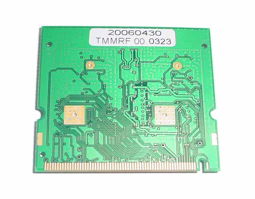
SU5-MSR-RTWAVE
Mar 25, 2008MSR Radio Module
Equipment Class
DTS - Digital Transmission System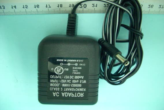
SU5-TMX5808
Sep 24, 20065.8GHz Tx Module
Equipment Class
DXX - Part 15 Low Power Communication Device Transmitter