SU7310MCD21KModel 310MCD21K
Controlled Entry Distributors, Inc.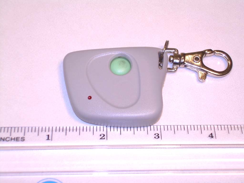
Click to zoom
Application Details
- Equipment Class
- DSC - Part 15 Security/Remote Control Transmitter
- Date of Grant
- Jan 14, 2007
- Application Purpose
- Original Equipment
- Date of Application
- Jan 14, 2007
- Equipment Note
- Model 310MCD21K
- Frequency Range
- 310.00000000 - 310.00000000
- Country
- United States
Documents & Files
Document Text
Text extracted from the exhibit documents filed with the FCC. Open a document above to read the original.
External Photos
Front View of the EUT Back View of the EUT
Internal Photos
View of the Component Side of the PCB View of the Trace Side of the PCB
Test Report
COMMUNICATION CERTIFICATION LABORATORY 1940 West Alexander Street Salt Lake City, UT 84119 801-972-6146 Test Report Certification Test Of: 310MCD21K FCC ID: SU7310MCD21K Test Specification: FCC PART 15, Subpart C Section 15.231 Test Report Serial No: 73-8420 Applicant: Controlled Entry Distributors, Inc. DBA Community Controls 2500 South 3850 West, Suite A Salt Lake City, UT 84120 Date of Test: November 7, 2006 Issue Date: November 9, 2006 Accredited Testing Laboratory By: NVLAP Lab Code 100272-0 COMMUNICATION CERTIFICATION LABORATORY TEST REPORT: 73-8420 FCC ID: SU7310MCD21K Page 2 of 27 CERTIFICATION OF ENGINEERING REPORT This report has been prepared by Communication Certification Laboratory to determine compliance of the device described below with the certification requirements of FCC Part 15, Subpart C Section 15.231. This report may be reproduced in full, partial reproduction may only be made with the written consent of the laboratory. The results in this report apply only to the sample tested. - Applicant: Controlled Entry Distributors, Inc. DBA Community Controls - Manufacturer: Lighting Tech Co., LTD - Trade Name: Community Controls - Model Number: 310MCD21K - FCC ID: SU7310MCD21K On this 9 th day of November 2006, I, individually, and for Communication Certification Laboratory, certify that the statements made in this engineering report are true, complete, and correct to the best of my knowledge, and are made in good faith. Although NVLAP has recognized that the Communication Certification Laboratory EMC testing facilities are in good standing, NVLAP does not endorse the product described in this report. COMMUNICATION CERTIFICATION LABORATORY Tested by: Norman P. Hansen EMC Technician COMMUNICATION CERTIFICATION LABORATORY TEST REPORT: 73-8420 FCC ID: SU7310MCD21K Page 3 of 27 TABLE OF CONTENTS SECTION 1.0 CLIENT INFORMATION..................................4 SECTION 2.0 EQUIPMENT UNDER TEST (EUT)..........................5 SECTION 3.0 TEST SPECIFICATION, METHODS & PROCEDURES............6 SECTION 5.0 SUMMARY OF TEST RESULTS............................11 SECTION 6.0 MEASUREMENTS, EXAMINATIONS AND DERIVED RESULTS.....12 APPENDIX 2 PHOTOGRAPHS.........................................21 COMMUNICATION CERTIFICATION LABORATORY TEST REPORT: 73-8420 FCC ID: SU7310MCD21K Page 4 of 27 SECTION 1.0 CLIENT INFORMATION 1.1 Client Information: Company Name: Controlled Entry Distributors, Inc. DBA Community Controls 2500 South 3850 West, Suite A Salt Lake City, UT 84120 Contact Name: Brad Kofford Title: President 1.2 Manufacturer: Company Name: Lighting Tech Co., LTD 4F, No. 124 Hua Chen Rd. Hsing Chuang City, Taipei Hsien Taiwan, R.O.C. Contact Name: N. J. Duan Title: Sales Manager COMMUNICATION CERTIFICATION LABORATORY TEST REPORT: 73-8420 FCC ID: SU7310MCD21K Page 5 of 27 SECTION 2.0 EQUIPMENT UNDER TEST (EUT) 2.1 Identification of EUT: Trade Name: Community Controls Model Number: 310MCD21K Serial Number: None Options Fitted: N/A Country of Manufacture: Taiwan 2.2 Description of EUT: The 310MCD21K is a one-button transmitter operating at 310 MHz. Encoding is performed by toggling the 10 DIP switches to either the on or off position. The 310MCD21K is for use with automated gates, access control panels, or garage door openers that operate at 310 MHz. COMMUNICATION CERTIFICATION LABORATORY TEST REPORT: 73-8420 FCC ID: SU7310MCD21K Page 6 of 27 SECTION 3.0 TEST SPECIFICATION, METHODS & PROCEDURES 3.1 Test Specification: Title: FCC PART 15, Subpart C (47 CFR 15). Section 15.231 Periodic operation in the band 40.66-40.70 MHz and above 70 MHz. Purpose of Test: The tests were performed to demonstrate Initial compliance. 3.2 Methods & Procedures: 3.2.1 §15.231 (a) The provision of this section are restricted to periodic operation within the band 40.66-40.70 MHz and above 70 MHz. Except as Shown in paragraph (e) of this section, the intentional radiator is restricted to the transmission of a control signal such as those used with alarm systems, door openers, remote switches, etc. Radio control of toys is not permitted. Continuous transmissions, such as voice or video, and data transmissions are not permitted. The prohibition against data transmissions does not preclude the use of recognition codes. Those codes are used to identify the sensor that is activated or to identify the particular component as being part of the system. The following conditions shall be met to comply with the provisions for this periodic operation: (1) A manually operated transmitter shall employ a switch that will automatically deactivate the transmitter within not more than 5 seconds of being released. (2) A transmitter activated automatically shall cease transmission within 5 seconds after activation. (3) Periodic transmissions at regular predetermined intervals are not permitted. However, polling or supervision transmission to determine system integrity of transmitters used in security or safety applications are allowed if the periodic rate of transmission does not exceed one transmission of not more than one second duration per hour for each transmitter. (4) Intentional radiators which are employed for radio control purposes during emergencies involving fire, security, and COMMUNICATION CERTIFICATION LABORATORY TEST REPORT: 73-8420 FCC ID: SU7310MCD21K Page 7 of 27 safety of life, when activated to signal an alarm, may operate during the pendency of the alarm condition. (b) In addition to the provisions of §15.205, the field strength of emission from intentional radiators operated under this section shall not exceed the following: Fundamental frequency (MHz) Field strength of fundamental (microvolts/meter) Field strength of spurious emissions (microvolts/meter) 40.66 - 40.70 2,250 225 70 –130 1,250 125 130 – 174 1,250 to 3,750 ** 125 to 375 ** 174 – 260 3,750 375 260 – 470 3,750 to 12,500 ** 375 to 1,250 ** Above 470 12,500 1,250 ** Linear interpolations (1) the above field strength limits are specified at a distance of …
Text truncated - open the document above for the full version.
Test Setup Photos
View of the Radiated Emission Test Setup (Vertical Alignment) View of the Radiated Emission Test Setup (Horizontal Face Alignment) View of the Radiated Emission Test Setup (Horizontal Flat Alignment)
Contact Information
Applicant
Bradley C Kofford(President)
Test Firm
Nemko-CCL, IncThomas Jackson
Technical Specifications
| # | Rule Parts | Frequency Range | Power Output |
|---|---|---|---|
| 1 | 15.231 | 310 MHz - 310 MHz | - |
Other Applications from Controlled Entry Distributors, Inc.
SU7318TRS8
Dec 12, 2022Part 15 Security / Remote Control Transmitter
Equipment Class
DSC - Part 15 Security/Remote Control Transmitter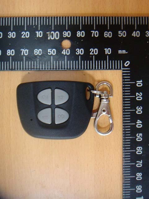
SU7IV318W4K
Oct 29, 2015Remote Controller
Equipment Class
DSC - Part 15 Security/Remote Control Transmitter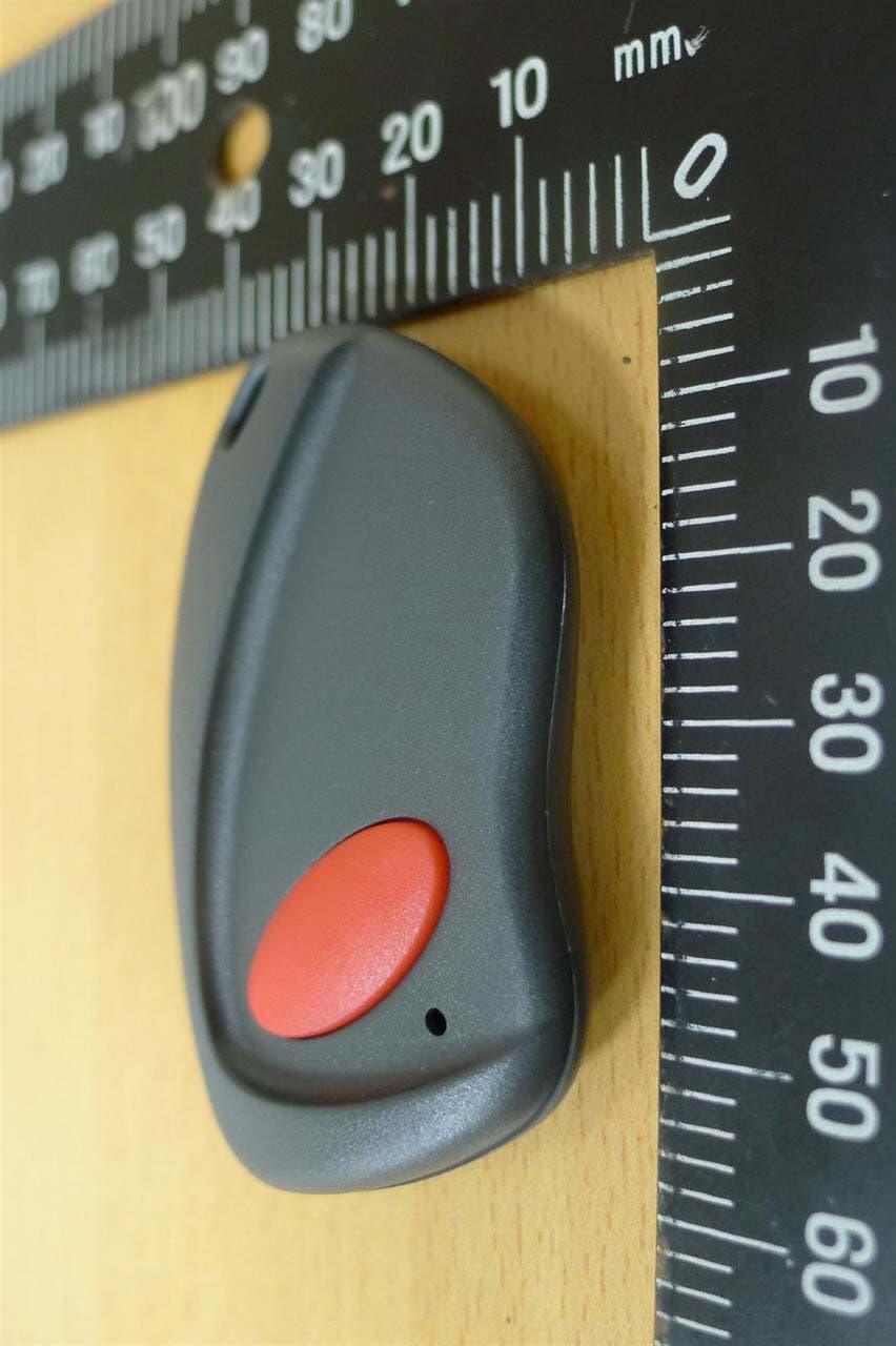
SU7INOX
Sep 30, 2015Remote Controller
Equipment Class
DSC - Part 15 Security/Remote Control Transmitter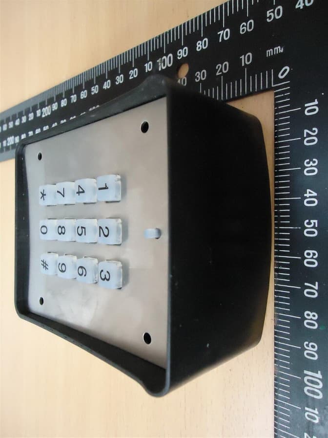
SU7DOL433RCP6SQ
Sep 12, 2015Remote Control
Equipment Class
DSC - Part 15 Security/Remote Control Transmitter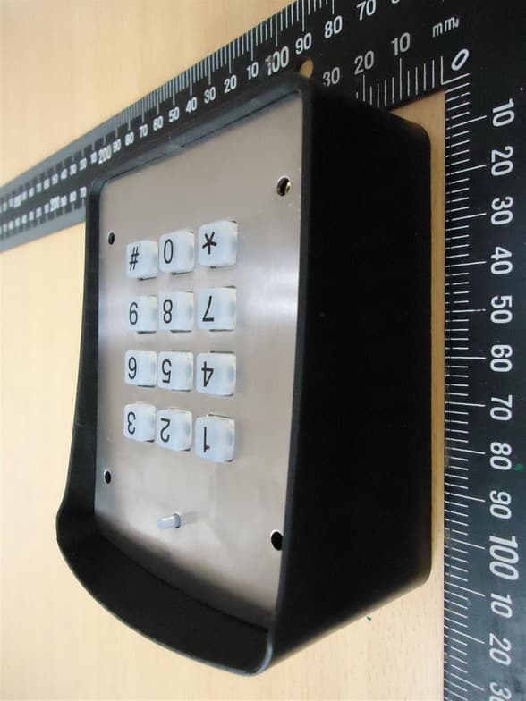
SU7DOL433RC6SQ
Sep 12, 2015Remote Control
Equipment Class
DSC - Part 15 Security/Remote Control Transmitter