SU7318LIPW1KModels 318LIPW1K, 318DOPW1K
Controlled Entry Distributors, Inc.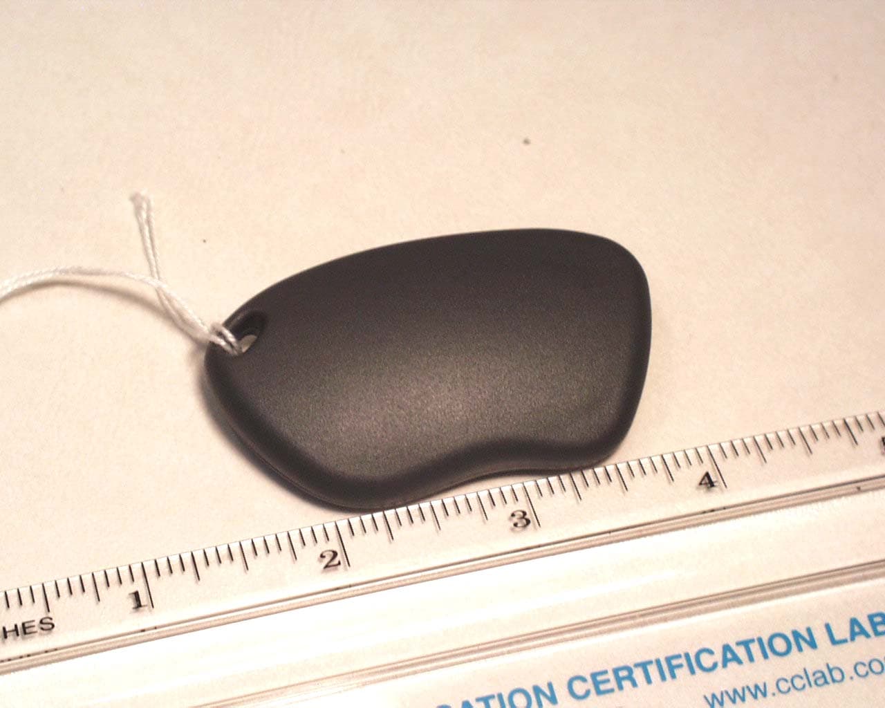
Click to zoom
Application Details
- Equipment Class
- DSC - Part 15 Security/Remote Control Transmitter
- Date of Grant
- Jun 19, 2006
- Application Purpose
- Original Equipment
- Date of Application
- Jun 19, 2006
- Equipment Note
- Models 318LIPW1K, 318DOPW1K
- Frequency Range
- 318.00000000 - 318.00000000
- Country
- United States
Documents & Files
Document Text
Text extracted from the exhibit documents filed with the FCC. Open a document above to read the original.
Users Manual
CONTENTS 1A - General information1B - Technical specifications1C - Main components 1 - TRANSMITTER OVERVIEW 2 - NUMBERING 3 - PROGRAMMING4 - OPERATION 5 - BATTERY ACCESS 1B - Technical specificationsOperating frequency 318 MHz Number of keys: 1 Battery life: 18 24 months Battery : 2 x 3V lithium batteries CR2016 ÷ Number combinations : 65,536 Protocol : Linear compatible Different Facilities codes 16 Operating temperature: -20°F÷+131°F (-20°C÷+55°C) Overall dimensions: 2.4”x1.4”x0.51” (61x36x13 mm) Weight: 0.49 oz. (14 gr.) 1C - Main components Red LED Key holder ring Blue push-button Transmitter Solutions Thank you for choosing a Transmitter Solutions product . Please read this manual carefully before using the product. Made in Italy. Copyright © 2006 by Transmitter Solutions 6 - TROUBLESHOOTING Manual MONARCH 318LIPW1K Dark grey case Fig. 2 1A - General informationThe Transmitter Solutions - Monarch 318LIPW1K transmitter is a keychain style mini transmitter operating at 318 MHz. It has been designedfor use with programmable telephone entry, security, and access controlsystems operating with a 318 MHz frequency receiver. The code sent bythe transmitter includes a 16 bit security code which allows up to65,536 code combinations and 4 bits of facility code which allows up to16 facility codes . The Transmitter Solutions - 318R receiver which operates with thistransmitter has a Wiegand 26 bit output and can operate any type ofaccess control system equipped with the same protocol. The CR 2016lithium batteries of the transmitter have a shelf life of about 6 months. Part 15 of FCC Regulations and The product fully complies with the European Directives 99/5/CE, 89/336/CEE, 73/23/CEE. 2 - NUMBERING 6 - TROUBLESHOOTING PROBLEM SOLUTION The operating range is reduced Check to verify the transmitter is programmed into your system Replace the transmitter batteries IS-TM13LCCUK Rev. 1 del 22.03.2006 To access the battery open the case with a screwdriver acting on the slot betweenthe cover and the bottom and remove the bottom, as shown in fig. 3a and 3b.Slide out the old batteries and replace them with the new ones ] respecting the polarity, with the positive (+) side upward. [CR2016 NOTE: Please dispose of the batteries properly according to local laws andregulations.Test proper battery installation by verifying that the red LED illuminates whenthe button is pushed. 5 - BATTERY ACCESS 3 - PROGRAMMING Each transmitter is manufactured and sold with a different factory-set serialnumber .The transmitter must be programmed into your system memory.Your own installer or reseller will provide you the necessary instructions for yoursystem. Replace the transmitter batteries The warranty period of 318 transmitters is 24 months, beginning from the manufacturing date of the transmitter. During this period, if theproduct does operate correctly, due to a defective component, the product will berepaired or replaced at the sole discretion of . The warranty does not extend to the transmitter case which can be damaged byconditions outside the control of or to battery life. Transmitter Solutions Transmitter Solutions Transmitter Solutions WARRANTY Transmitter Solutions - Type : 318LIPW1K FCC ID : SU7318LIPW1K This device complies with FCC Rules Operation is subject to the following two conditions:(1) This device may not cause harmful interference, and(2) this device must accept interference received, includinginterference that may cause undesired operation. Part.15ofthe Notice Any changes or modification to equipment not expressly approved by could void the manufacturer’s warranty. Transmitter Solutions Transmitter Solutions The system does not receiver the transmitter signal. The transmitter LED is ON The system does not receiver the transmitter signal. The transmitter LED will not light 4 - OPERATION A - Firmly depress the button until the small red LED illuminates.B - After the LED has illuminated, release the button.If the device you are attempting to activate does not respond, repeat steps A and Bor consult section 6 ( Troubleshooting ) of this manual. TRANSMITTER SOLUTIONS 2505 Chandler Avenue, Suite, 1 Las Vegas, NV 89120 - (866)975-0101 - (866) 975-0404 Fax [email protected] Fig. 3a Fig. 3b CONTENTS 1A - General information1B - Technical specifications1C - Main components 1 - TRANSMITTER OVERVIEW 2 - NUMBERING 3 - PROGRAMMING4 - OPERATION 5 - BATTERY ACCESS 1B - Technical specificationsOperating frequency 318 MHz Number of keys: 1 Battery life: 18 24 months Battery : 2 x 3V lithium batteries CR2016 ÷ Number combinations : 16,384 Protocol : MicroCLIK® compatible Different Facilities codes 64 Operating temperature: -20°F÷+131°F (-20°C÷+55°C) Overall dimensions: 2.4”x1.4”x0.51” (61x36x13 mm) Weight: 0.49 oz. (14 gr.) 1C - Main components Red LED Key holder ring Red push-button 6 - TROUBLESHOOTING Manual MONARCH 318DOPW1K Dark grey case Fig. 2 1A - General informationThe Transmitter Solutions - Monarch 318DOPW1K transmitter is a keychain style mini transmitter operating at 318 MHz. It has been designedfor use with programmable telephone entry, security, and access controlsystems operating with a 318 MHz frequency receiver. The protocol isMicroCLIK® compatible and the code sent by the transmitter includes a14 bit security code which allows up to 16384 code combinations and6 bits of facility code, which allows up to 64 facility codes . The Transmitter Solutions - 318R receiver which operates with thistransmitter has a Wiegand 26 bit output and can operate any type ofaccess control system equipped with the same protocol. The CR 2016lithium batteries of the transmitter have a shelf life of about 6 months. Part 15 of FCC Regulations and The product fully complies with the European Directives 99/5/CE, 89/336/CEE, 73/23/CEE. Transmitter Solutions Thank you for choosing a Transmitter Solutions product . Please read this manual carefully before using the product. Made in Italy. Copyright © 2006 by Transmitter Sol…
Text truncated - open the document above for the full version.
External Photos
Front View of the EUT Back View of the EUT
ID Label/Location Info
ELPRO INNOTEK S.p.A. TCF-106 Annex 1 = Label and placement Pag 2 of 2 Annex 1B : 318LIPW1K Label and placement case cartonbox
Internal Photos
View of the Component Side of the PCB View of the Trace Side of the PCB
Operational Description
CONTENTS 1A - General information1B - Technical specifications1C - Main components 1 - TRANSMITTER OVERVIEW 2 - NUMBERING 3 - PROGRAMMING4 - OPERATION 5 - BATTERY ACCESS 1B - Technical specificationsOperating frequency 318 MHz Number of keys: 1 Battery life: 18 24 months Battery : 2 x 3V lithium batteries CR2016 ÷ Number combinations : 65,536 Protocol : Linear compatible Different Facilities codes 16 Operating temperature: -20°F÷+131°F (-20°C÷+55°C) Overall dimensions: 2.4”x1.4”x0.51” (61x36x13 mm) Weight: 0.49 oz. (14 gr.) 1C - Main components Red LED Key holder ring Blue push-button Transmitter Solutions Thank you for choosing a Transmitter Solutions product . Please read this manual carefully before using the product. Made in Italy. Copyright © 2006 by Transmitter Solutions 6 - TROUBLESHOOTING Manual MONARCH 318LIPW1K Dark grey case Fig. 2 1A - General informationThe Transmitter Solutions - Monarch 318LIPW1K transmitter is a keychain style mini transmitter operating at 318 MHz. It has been designedfor use with programmable telephone entry, security, and access controlsystems operating with a 318 MHz frequency receiver. The code sent bythe transmitter includes a 16 bit security code which allows up to65,536 code combinations and 4 bits of facility code which allows up to16 facility codes . The Transmitter Solutions - 318R receiver which operates with thistransmitter has a Wiegand 26 bit output and can operate any type ofaccess control system equipped with the same protocol. The CR 2016lithium batteries of the transmitter have a shelf life of about 6 months. Part 15 of FCC Regulations and The product fully complies with the European Directives 99/5/CE, 89/336/CEE, 73/23/CEE. 2 - NUMBERING 6 - TROUBLESHOOTING PROBLEM SOLUTION The operating range is reduced Check to verify the transmitter is programmed into your system Replace the transmitter batteries IS-TM13LCCUK Rev. 1 del 22.03.2006 To access the battery open the case with a screwdriver acting on the slot betweenthe cover and the bottom and remove the bottom, as shown in fig. 3a and 3b.Slide out the old batteries and replace them with the new ones ] respecting the polarity, with the positive (+) side upward. [CR2016 NOTE: Please dispose of the batteries properly according to local laws andregulations.Test proper battery installation by verifying that the red LED illuminates whenthe button is pushed. 5 - BATTERY ACCESS 3 - PROGRAMMING Each transmitter is manufactured and sold with a different factory-set serialnumber .The transmitter must be programmed into your system memory.Your own installer or reseller will provide you the necessary instructions for yoursystem. Replace the transmitter batteries The warranty period of 318 transmitters is 24 months, beginning from the manufacturing date of the transmitter. During this period, if theproduct does operate correctly, due to a defective component, the product will berepaired or replaced at the sole discretion of . The warranty does not extend to the transmitter case which can be damaged byconditions outside the control of or to battery life. Transmitter Solutions Transmitter Solutions Transmitter Solutions WARRANTY Transmitter Solutions - Type : 318LIPW1K FCC ID : SU7318LIPW1K This device complies with FCC Rules Operation is subject to the following two conditions:(1) This device may not cause harmful interference, and(2) this device must accept interference received, includinginterference that may cause undesired operation. Part.15ofthe Notice Any changes or modification to equipment not expressly approved by could void the manufacturer’s warranty. Transmitter Solutions Transmitter Solutions The system does not receiver the transmitter signal. The transmitter LED is ON The system does not receiver the transmitter signal. The transmitter LED will not light 4 - OPERATION A - Firmly depress the button until the small red LED illuminates.B - After the LED has illuminated, release the button.If the device you are attempting to activate does not respond, repeat steps A and Bor consult section 6 ( Troubleshooting ) of this manual. TRANSMITTER SOLUTIONS 2505 Chandler Avenue, Suite, 1 Las Vegas, NV 89120 - (866)975-0101 - (866) 975-0404 Fax [email protected] Fig. 3a Fig. 3b CONTENTS 1A - General information1B - Technical specifications1C - Main components 1 - TRANSMITTER OVERVIEW 2 - NUMBERING 3 - PROGRAMMING4 - OPERATION 5 - BATTERY ACCESS 1B - Technical specificationsOperating frequency 318 MHz Number of keys: 1 Battery life: 18 24 months Battery : 2 x 3V lithium batteries CR2016 ÷ Number combinations : 16,384 Protocol : MicroCLIK® compatible Different Facilities codes 64 Operating temperature: -20°F÷+131°F (-20°C÷+55°C) Overall dimensions: 2.4”x1.4”x0.51” (61x36x13 mm) Weight: 0.49 oz. (14 gr.) 1C - Main components Red LED Key holder ring Red push-button 6 - TROUBLESHOOTING Manual MONARCH 318DOPW1K Dark grey case Fig. 2 1A - General informationThe Transmitter Solutions - Monarch 318DOPW1K transmitter is a keychain style mini transmitter operating at 318 MHz. It has been designedfor use with programmable telephone entry, security, and access controlsystems operating with a 318 MHz frequency receiver. The protocol isMicroCLIK® compatible and the code sent by the transmitter includes a14 bit security code which allows up to 16384 code combinations and6 bits of facility code, which allows up to 64 facility codes . The Transmitter Solutions - 318R receiver which operates with thistransmitter has a Wiegand 26 bit output and can operate any type ofaccess control system equipped with the same protocol. The CR 2016lithium batteries of the transmitter have a shelf life of about 6 months. Part 15 of FCC Regulations and The product fully complies with the European Directives 99/5/CE, 89/336/CEE, 73/23/CEE. Transmitter Solutions Thank you for choosing a Transmitter Solutions product . Please read this manual carefully before using the product. Made in Italy. Copyright © 2006 by Transmitter Sol…
Text truncated - open the document above for the full version.
Test Report
COMMUNICATION CERTIFICATION LABORATORY 1940 West Alexander Street Salt Lake City, UT 84119 801-972-6146 Test Report Certification TEST OF: 318LIPW1K FCC ID: SU7318LIPW1K To FCC PART 15, Subpart C Section 15.231 Test Report Serial No: 73-8299 Applicant: Controlled Entry Distributors, Inc. DBA Community Controls 2500 South 3850 West, Suite A Salt Lake City, UT 84120 Date of Test: May 8, 2006 Issue Date: May 8, 2006 Accredited Testing Laboratory By: NVLAP Lab Code 100272-0 COMMUNICATION CERTIFICATION LABORATORY TEST REPORT: 73-8299 FCC ID: SU7318LIPW1K Page 2 of 30 CERTIFICATION OF ENGINEERING REPORT This report has been prepared by Communication Certification Laboratory to determine compliance of the device described below with the certification requirements of FCC Part 15, Subpart C Section 15.231. This report may be reproduced in full, partial reproduction may only be made with the written consent of the laboratory. The results in this report apply only to the sample tested. - Applicant: Controlled Entry Distributors, Inc. DBA Community Controls - Manufacturer: Elpro Innotek sri - Trade Name: Monarch - Model Number: 318LIPW1K - FCC ID: SU7318LIPW1K On this 8 th day of May 2006, I, individually, and for Communication Certification Laboratory, certify that the statements made in this engineering report are true, complete, and correct to the best of my knowledge, and are made in good faith. Although NVLAP has recognized that the Communication Certification Laboratory EMC testing facilities are in good standing, NVLAP does not endorse the product described in this report. COMMUNICATION CERTIFICATION LABORATORY Tested by: Norman P. Hansen EMC Technician COMMUNICATION CERTIFICATION LABORATORY TEST REPORT: 73-8299 FCC ID: SU7318LIPW1K Page 3 of 30 TABLE OF CONTENTS SECTION 1.0 CLIENT INFORMATION..................................4 SECTION 2.0 EQUIPMENT UNDER TEST (EUT)..........................5 SECTION 3.0 TEST SPECIFICATION, METHODS & PROCEDURES............6 SECTION 5.0 SUMMARY OF TEST RESULTS............................12 SECTION 6.0 MEASUREMENTS, EXAMINATIONS AND DERIVED RESULTS.....13 APPENDIX 2 PHOTOGRAPHS.........................................24 COMMUNICATION CERTIFICATION LABORATORY TEST REPORT: 73-8299 FCC ID: SU7318LIPW1K Page 4 of 30 SECTION 1.0 CLIENT INFORMATION 1.1 Client Information: Company Name: Controlled Entry Distributors, Inc. DBA Community Controls 2500 South 3850 West, Suite A Salt Lake City, UT 84120 Contact Name: Brad Kofford Title: President 1.2 Manufacturer: Company Name: Elpro Innotek sri Via Piave, 23 31020 S. Pietro Di Feletto Treviso, Italy Contact Name: Massimo Dalle Carbonare Title: Engineer COMMUNICATION CERTIFICATION LABORATORY TEST REPORT: 73-8299 FCC ID: SU7318LIPW1K Page 5 of 30 SECTION 2.0 EQUIPMENT UNDER TEST (EUT) 2.1 Identification of EUT: Trade Name: Monarch Model Number: 318LIPW1K Serial Number: None Options Fitted: N/A Country of Manufacture: Italy 2.2 Description of EUT: The 318LIPW1K is a one-button, pulsed emission, transmitter operating periodically at 318 MHz. The 318LIPW1K is for use with automated gates, access control panels, or garage door openers that operate at 318 MHz. Power is supplied by two CR2016, 3 Vdc, lithium batteries. COMMUNICATION CERTIFICATION LABORATORY TEST REPORT: 73-8299 FCC ID: SU7318LIPW1K Page 6 of 30 SECTION 3.0 TEST SPECIFICATION, METHODS & PROCEDURES 3.1 Test Specification: Title: FCC PART 15, Subpart C (47 CFR 15). Section 15.231 Periodic operation in the band 40.66-40.70 MHz and above 70 MHz. Purpose of Test: The tests were performed to demonstrate Initial compliance. 3.2 Methods & Procedures: 3.2.1 §15.203 An intentional radiator shall be designed to ensure that no antenna other than that furnished by the responsible party shall be used with the device. The use of a permanently attached antenna or of an antenna that uses a unique coupling to the intentional radiator shall be considered sufficient to comply with the provisions of this Section. The manufacturer may design the unit so that a broken antenna can be replaced by the user, but the use of a standard antenna jack or electrical connector is prohibited. This requirement does not apply to carrier current devices or to devices operated under the provisions of Sections 15.211, 15.213, 15.217, 15.219, or 15.221. Further, this requirement does not apply to intentional radiators that must be professionally installed, such as perimeter protection systems and some field disturbance sensors, or to other intentional radiators which, in accordance with Section 15.31(d), must be measured at the installation site. However, the installer shall be responsible for ensuring that the proper antenna is employed so that the limits in this Part are not exceeded. 3.2.2 §15.231 (a) The provision of this section are restricted to periodic operation within the band 40.66-40.70 MHz and above 70 MHz. Except as Shown in paragraph (e) of this section, the intentional radiator is restricted to the transmission of a control signal such as those used with alarm systems, door openers, remote switches, etc. Radio control of toys is not permitted. Continuous transmissions, such as voice or video, and data transmissions are not permitted. The prohibition against data COMMUNICATION CERTIFICATION LABORATORY TEST REPORT: 73-8299 FCC ID: SU7318LIPW1K Page 7 of 30 transmissions does not preclude the use of recognition codes. Those codes are used to identify the sensor that is activated or to identify the particular component as being part of the system. The following conditions shall be met to comply with the provisions for this periodic operation: (1) A manually operated transmitter shall employ a switch that will automatically deactivate the transmitter within not more than 5 seconds of being released. (2) A transmitter activated automatically shall cease transmission within 5 seconds after activation. (3) Periodic transmissions at regular predetermined intervals are not permitted. However, pollin…
Text truncated - open the document above for the full version.
Test Setup Photos
View of the Radiated Emission Test Setup (Vertical Alignment) View of the Radiated Emission Test Setup (Horizontal Face Alignment) View of the Radiated Emission Test Setup (Horizontal Flat Alignment)
Contact Information
Applicant
Bradley C Kofford(President)
Test Firm
Nemko-CCL, IncThomas Jackson
Technical Specifications
| # | Rule Parts | Frequency Range | Power Output |
|---|---|---|---|
| 1 | 15.231 | 318 MHz - 318 MHz | - |
Other Applications from Controlled Entry Distributors, Inc.
SU7318TRS8
Dec 12, 2022Part 15 Security / Remote Control Transmitter
Equipment Class
DSC - Part 15 Security/Remote Control Transmitter
SU7IV318W4K
Oct 29, 2015Remote Controller
Equipment Class
DSC - Part 15 Security/Remote Control Transmitter
SU7INOX
Sep 30, 2015Remote Controller
Equipment Class
DSC - Part 15 Security/Remote Control Transmitter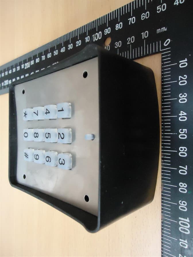
SU7DOL433RCP6SQ
Sep 12, 2015Remote Control
Equipment Class
DSC - Part 15 Security/Remote Control Transmitter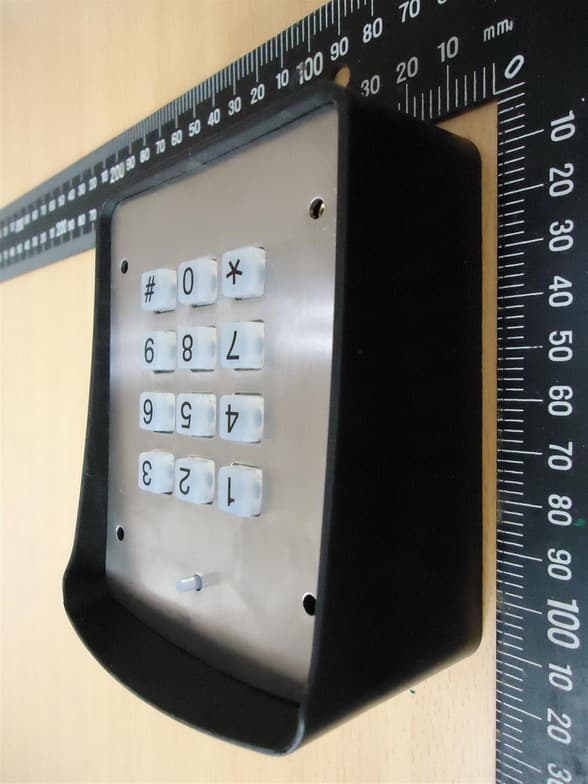
SU7DOL433RC6SQ
Sep 12, 2015Remote Control
Equipment Class
DSC - Part 15 Security/Remote Control Transmitter