SU7DOL1000-MF2Remote Controller
Controlled Entry Distributors, Inc.
Click to zoom
Application Details
- Equipment Class
- DSC - Part 15 Security/Remote Control Transmitter
- Date of Grant
- Jun 28, 2015
- Application Purpose
- Original Equipment
- Date of Application
- Jun 28, 2015
- Equipment Note
- Remote Controller
- Frequency Range
- 433.85000000 - 433.85000000
- Country
- United States
Documents & Files
Document Text
Text extracted from the exhibit documents filed with the FCC. Open a document above to read the original.
Users Manual
DOL1000-MF2 (2 Relay) Programming & Installation Manual INTRODUCTION The DOL1000-MF2 is a versatile keypad that has the option of running wirelessly. The DOL1000- MF2 can work with 6 volts of batte ry power or 6-24 volts of AC/DC. This keypad can be wired with multiple wireless transmitte rs. DOL1000-MF2 can store up to 1000 access codes. Guest access codes are also programmable, which are single-use codes for access. After 5 successive incorrect codes, the keypad will lock for 4 minutes CONNECTION TERMINALS • V+/V-: These terminals will supply power to the transmitte r. • ANT: Antenna • RF1-4: The DOL1000-MF2 can control up to 4 diffe rent channels. Each RF terminal represents a diffe rent channel. • GO: Connects to the green LED • NOGO: Connects to the red LED • KEYPADUTE: Connects to the DOL1000-MF2 lights located in front of the keypad • NO (Normally open): Use N.O. for equipment that requires a temporary surge of electricity to activate. Example, Electric door locks, automated gates, push plates, etc. • COM: Common ground • NC (Normally closed): Use N.C. for equipment that requires a constant flow of electricity to function properly. Example, Magnetic locks, receivers, etc. • BATTERY 6VDC: If deciding to power the DOL1000-MF2 with a batte ry, then connect the batte ry to these terminals. • 6-24VAC/DC: If deciding to hardwir e the DOL1000-MF2 directly to a power source, use these terminals. • Master Reset Button: Holding this butto n down for 5 seconds after reconnecting the keypad to its power source will make the keypad beep 3 times. This will indicate that the Master Code has been reset to 1234. RESETTING THE K EYPAD AND MASTER CODE Located on the DOL1000-MF2’s circuit board, the red Master Reset Butto n is used to reset the master code back to 1234. The follo wing steps will reset the master code: 1. Remove the batte ry or eliminate the power source to the DOL1000-MF2 and wait for 30 seconds for the keypad to completely power off. 2. Press and hold the red Master Reset Butto n. 3. While holding the red Master Reset Butto n, reconnect the batte ry or power source to the DOL1000-MF2. 4. Continue to hold the red Master Reset Butto n until the keypad beeps 3 times. This will indicate that the Master Code has been reset to 1234. The very first time that you apply powewr to the keypad, you will hear a series of beeps followed by a regular repeating beep (1 beep at 3 second intervals) that lets you know you are in programming mode: Enter a 4 digit Master Code that only you will use for programming purposes. Write Master Code here You can now add up to 1000 access codes as well as a flash code (for one use only) and a latch code to hold open the gate. To add Access Code 1934 To add Access Codes 2413, 888 and 9743 (you may add up to 1000 different codes) Example - Master Code 1234 Access Code: Master Code 1 2 3 41 9 3 4 Sub ModeAccess CodeChannelExit 1 #1 # To remove Access Code 1934 Master Code 1 2 3 41 9 3 4 Sub ModeAccess CodeExit 2 ## To change Master Code from 1234 to 4321 Master Code 1 2 3 44 3 2 1 Sub ModeNew Master CodeExit 7 ## To clear all Access, Flash and Latch codes Master Code 1 2 3 4 Sub Mode 8 # To add Flash Code 4437 (for one use only) Master Code 1 2 3 44 4 3 7 Sub ModeFlash CodeChannel 3 #1 To set relay output time 15 seconds (1/2 - 60 seconds) Master Code 1 2 3 41 5 # Sub Mode# Seconds 5 # To set relay output time 1/2 second 1 2 3 4 0 # 5 # Master Code 1 2 3 42 4 1 3 Sub ModeAccess CodeChannelExit 1 #2 # 8 8 8 83 # 9 7 4 34 # beep - Default Master Code: 1 234 Add Access 1 234, 1#, Access Code: __ __ __ __ , Channel:1 # Example: STEP 1: Press 1 2 3 4 STEP 2: Press 1 # STEP 3: Enter access code __ __ __ __ STEP 4: Press 1 # (multiple beeps confirm) STEP 5: Press * * STEP 6: Test new access code. __ __ __ __ (Green light will flash 6 times confirming that t he new access code has been accepted.) STEP 8: Proceed to program the keypad to the receiver. STEP 7: Install 433 MHz wireless module (see next page) Codes Use Channel 1 if unsure. The diffe rent channels are dependent on the RF terminal used. Any channel can be assigned for devices that connect to normally open/normally closed. 1 2 3 4, 2#, Access Code: __ __ __ __ , # Remove Access Codes Enter the Access Code you would like to delete. 1 2 3 4, 3#, Guest Code: __ __ __ __ , Channel:1 Add Guest Code The Guest Code is a one-time use access code. Once used, the number will be cleared from memory. 1 2 3 4, 4#, Toggle Code: __ __ __ __ , Channel:1 Add Access Toggle Code Entering Access Toggle Code will toggle the keypad to continuously activate. Entering the code again will toggle the keypad off. Dip switch #6 on the circuit board needs to be in the off position in order for this mode to work. TOGGLE MODE ONLY FOR USE WHEN KEYPAD IS HARD WIRED. 1 2 3 4, 5#, Seconds:0-60, # Set Relay Output Time Set the number of seconds the device will grant access before locking again. 1 2 3 4, 7#, Master Code: __ __ __ __ , # Change Master Code Changes Master Code. If the Master Code is forgotte n, this manual contains instructions on how to reset the Master Code. 1 2 3 4, 8# Clear All Codes This will clear all data except the Master Code. PROGRAMMING THEDOL1000-MF2 with 433 MHz Module INSTALLING THE 433 MHz MODULE Antenna Activation Wires: Common & Normally Open + - Channel 1 Channel 2 STEP1: Prepare the 433 MHz module STEP2: Remove (cut) the battery connector • NOTE: Be sure to connect the power source to the correct terminals! The batte ry terminals and the AC/DC terminals are diffe rent. • NOTE: Any channel can be assigned for devices that connect to normally open/normally closed. STEP 3: Install the 433 MHz Module to the keypad board DIP SWITCH MODULE INSTALLATION EXAMPLE: NOTE: Be sure to connect the power source to the correct terminals! The batte ry terminals and the AC/DC terminals are diffe rent. Relay 1 Relay 2 DIP SWITCHES 1. SOUND 2. LED 3. LIGHTS 4. Not used 5. Not used 6. WIRELESS MODE a. Switching this dip switch to off w…
Text truncated - open the document above for the full version.
External Photos
Registration number: W6M21503-14870-C-1 FCC ID: SU7DOL1000-MF2 Worldwide Testing Services(Taiwan) Co., Ltd Appendix Page 12 of 23 External Photos Registration number: W6M21503-14870-C-1 FCC ID: SU7DOL1000-MF2 Worldwide Testing Services(Taiwan) Co., Ltd Appendix Page 13 of 23 Registration number: W6M21503-14870-C-1 FCC ID: SU7DOL1000-MF2 Worldwide Testing Services(Taiwan) Co., Ltd Appendix Page 14 of 23
ID Label/Location Info
FCCID: SU7DOL1000-MF2
Internal Photos
Registration number: W6M21503-14870-C-1 FCC ID: SU7DOL1000-MF2 Worldwide Testing Services(Taiwan) Co., Ltd Appendix Page 15 of 23 Internal Photos Registration number: W6M21503-14870-C-1 FCC ID: SU7DOL1000-MF2 Worldwide Testing Services(Taiwan) Co., Ltd Appendix Page 16 of 23 Registration number: W6M21503-14870-C-1 FCC ID: SU7DOL1000-MF2 Worldwide Testing Services(Taiwan) Co., Ltd Appendix Page 17 of 23 Registration number: W6M21503-14870-C-1 FCC ID: SU7DOL1000-MF2 Worldwide Testing Services(Taiwan) Co., Ltd Appendix Page 18 of 23 Registration number: W6M21503-14870-C-1 FCC ID: SU7DOL1000-MF2 Worldwide Testing Services(Taiwan) Co., Ltd Appendix Page 19 of 23 Registration number: W6M21503-14870-C-1 FCC ID: SU7DOL1000-MF2 Worldwide Testing Services(Taiwan) Co., Ltd Appendix Page 20 of 23 Registration number: W6M21503-14870-C-1 FCC ID: SU7DOL1000-MF2 Worldwide Testing Services(Taiwan) Co., Ltd Appendix Page 21 of 23 Registration number: W6M21503-14870-C-1 FCC ID: SU7DOL1000-MF2 Worldwide Testing Services(Taiwan) Co., Ltd Appendix Page 22 of 23
Test Report
of Applicant: Controlled Entry Distributors, Inc. Address: 2500 South 3850 West Suite A Salt Lake City Utah United States 84120 Tested and Prepared by Worldwide Testing Services (Taiwan) Co., Ltd. FCC Registration No.: 930600 Industry Canada filed test laboratory Reg. No. IC 5679A-1, IC-5107A-1 A2LA Accredited No.: 2732.01 Report No.: W6M21503-14870-C-1 6F, NO. 58, LANE 188, RUEY-KUANG RD., NEIHU TAIPEI 114, TAIWAN, R.O.C. TEL: 886-2-66068877 FAX: 886-2-66068879 E-mail: [email protected] FCC PART 15 SUBPART C TEST REPORT for Remote Controller Model No.: DOL1000MF_2Relays FCC ID: SU7DOL1000-MF2 Registration number: W6M21503-14870-C-1 FCC ID: SU7DOL1000-MF2 Worldwide Testing Services(Taiwan) Co., Ltd Page 1 of 19 TABLE OF CONTENTS 1 General Information........................................................................................................................2 1.1 Notes ...........................................................................................................................................2 1.2 Testing laboratory .......................................................................................................................3 1.2.1 Location ..................................................................................................................................3 1.2.2 Details of accreditation status ................................................................................................3 1.3 Details of approval holder...........................................................................................................3 1.4 Application details ......................................................................................................................4 1.5 Test item .....................................................................................................................................4 1.6 Test standards .............................................................................................................................4 2 Technical test ..................................................................................................................................5 2.1 Summary of test results...............................................................................................................5 2.2 Test environment ........................................................................................................................5 2.3 Test equipment utilized...............................................................................................................6 2.4 General Test Procedure...............................................................................................................8 3 Test results (enclosure) ...................................................................................................................9 3.1 Transmission Requirements......................................................................................................10 3.1.1 Limit of Transmission Time ..................................................................................................10 3.1.2 Active Time ...........................................................................................................................10 3.2 Output Power (Field Strength)..................................................................................................11 3.3 Out of Band Radiated Emissions ..............................................................................................12 3.4 Transmitter Radiated Emissions in restricted Bands ................................................................13 3.5 Spurious Emission radiated, Transmitter ..................................................................................14 3.6 Channel Bandwidth...................................................................................................................16 3.7 Antenna requirement.................................................................................................................17 3.8 Duty Cycle ................................................................................................................................18 3.9 Conducted Measurement at (AC) Power Line..........................................................................19 Appendix: Diagrams and photos Registration number: W6M21503-14870-C-1 FCC ID: SU7DOL1000-MF2 Worldwide Testing Services(Taiwan) Co., Ltd Page 2 of 19 1 General Information 1.1 Notes The purpose of conformity testing is to increase the probability of adherence to the essential requirements or conformity specifications, as appropriate. The complexity of the technical specifications, however, means that full and thorough testing is impractical for both technical and economic reasons. Furthermore, there is no guarantee that a test sample which has passed all the relevant tests conforms to a specification. Neither is there any guarantee that such a test sample will interwork with other genuinely open systems. The existence of the tests nevertheless provides the confidence that the test sample possesses the qualities as maintained and that is performance generally conforms to representative cases of communications equipment. The test results of this test report relate exclusively to the item tested as specified in 1.5. The test report may only be reproduced or published in full. Reproduction or publication of extracts from the report requires the prior written approval of the Worldwide Testing Services(Taiwan) Co., Ltd. Tester: March 31, 2015 Leon Chueh Date WTS-Lab. Name Signature Technical responsibility for area of testing: March 31, 2015 Kevin Wang Date WTS Name Signature Registration number: W6M21503-14870-C-1 FCC ID: SU7DOL1000-MF2 Worldwide Testing Services(Taiwan) Co., Ltd Page 3 of 19 1.2 Testing laboratory 1.2.1 Location OATS No.5-1, Lishui, Shuang Sing Village, Wanli Dist., New Taipei City 207, Taiwan (…
Text truncated - open the document above for the full version.
Test Setup Photos
Registration number: W6M21503-14870-C-1 FCC ID: SU7DOL1000-MF2 Worldwide Testing Services(Taiwan) Co., Ltd Appendix Page 23 of 23 Set Up Photos of Radiated emission
Contact Information
Applicant
Bradley C Kofford(President)
Technical Contact
Worldwide Testing Services (Taiwan) Co., Ltd.Danny Sung
[email protected]+886-2-6606-8877
6F., No. 58, Lane 188, Ruey Kuand Rd. · Taipei · Taiwan
Test Firm
Worldwide Testing Services (Taiwan) Co., Ltd.Rex Kao
Technical Specifications
| # | Rule Parts | Frequency Range | Power Output |
|---|---|---|---|
| 1 | 15.231 | 433.85 MHz - 433.85 MHz | - |
Other Applications from Controlled Entry Distributors, Inc.
SU7318TRS8
Dec 12, 2022Part 15 Security / Remote Control Transmitter
Equipment Class
DSC - Part 15 Security/Remote Control Transmitter
SU7IV318W4K
Oct 29, 2015Remote Controller
Equipment Class
DSC - Part 15 Security/Remote Control Transmitter
SU7INOX
Sep 30, 2015Remote Controller
Equipment Class
DSC - Part 15 Security/Remote Control Transmitter
SU7DOL433RCP6SQ
Sep 12, 2015Remote Control
Equipment Class
DSC - Part 15 Security/Remote Control Transmitter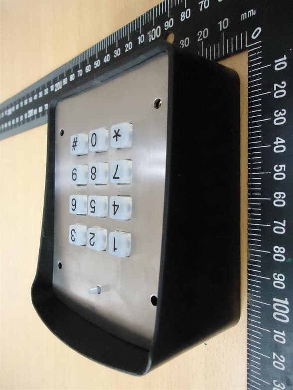
SU7DOL433RC6SQ
Sep 12, 2015Remote Control
Equipment Class
DSC - Part 15 Security/Remote Control Transmitter