SU7FM420U433.9 MHz REMOTE TRANSMITTER
Controlled Entry Distributors, Inc.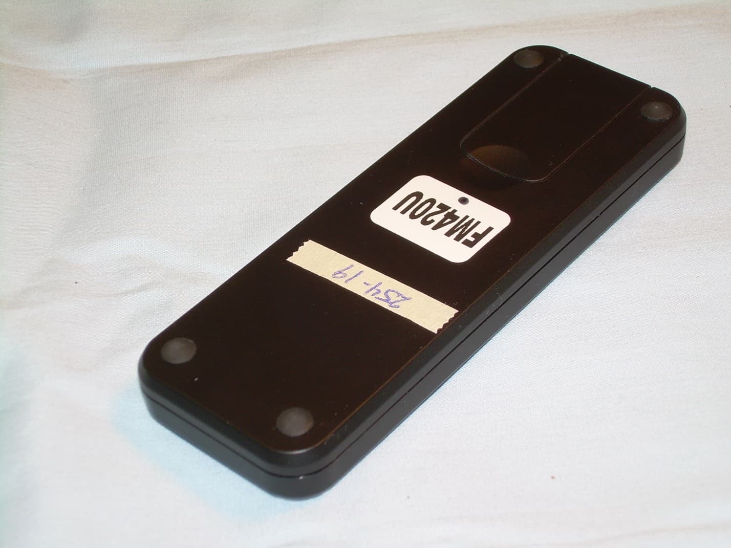
Click to zoom
Application Details
- Equipment Class
- DSC - Part 15 Security/Remote Control Transmitter
- Date of Grant
- Nov 25, 2013
- Application Purpose
- Original Equipment
- Date of Application
- Nov 25, 2013
- Equipment Note
- 433.9 MHz REMOTE TRANSMITTER
- Frequency Range
- 433.90000000 - 433.90000000
- Country
- United States
Documents & Files
Document Text
Text extracted from the exhibit documents filed with the FCC. Open a document above to read the original.
Users Manual
FM420U ISTFM420U V.06.2013 EN MULTI-CHANNEL 433.92 MHz RADIO CONTROL. Operation and programming instructions. EN Fig. 1 Fig. 2 2 2 CR2430 2 1 4 . 2 1 1 6 . 0 40.8 dimensions in mm 20 1 3 5 4 DISPLAY EN 3 SPECIFICATIONS Multi-channel radio control for quick and intuitive control of 20 users with receivers in the series FM400U Innovative and stylish container with white led display which, located under semi-transparent plastic, shows the selected channel. At the centre of a rubber faced keypad with three function keys and two up-down channel selection keys. Fitted with practical non-slip rubber buttons. TECHNICAL SPECIFICATIONS u.m. FM420 Power supply with battery typeVdc3 (CR2430) Transmission consumptionmA50 FrequencyMHz433,92 ModulationFSK Operating temperature°C-20 +55 Any changes or modifications not expressly approved by the party responsible for compliance could void the user's authority to operate this equipment. Tested to Comply with FCC Standards FOR HOME OR OFFICE USE. Operation is subject to the following two conditions: (1) This device may not cause harmful interference, and (2) this device must accept any interference received, including interference that may cause undesired operation. EN Fig. 1 Fig. 2 2 2 CR2430 2 1 4 . 2 1 1 6 . 0 40.8 dimensions in mm 20 1 3 5 4 DISPLAY EN 3 SPECIFICATIONS Multi-channel radio control for quick and intuitive control of 20 users with receivers in the series FM400U Innovative and stylish container with white led display which, located under semi-transparent plastic, shows the selected channel. At the centre of a rubber faced keypad with three function keys and two up-down channel selection keys. Fitted with practical non-slip rubber buttons. TECHNICAL SPECIFICATIONS u.m. FM420 Power supply with battery typeVdc3 (CR2430) Transmission consumptionmA50 FrequencyMHz433,92 ModulationFSK Operating temperature°C-20 +55 Any changes or modifications not expressly approved by the party responsible for compliance could void the user's authority to operate this equipment. Tested to Comply with FCC Standards FOR HOME OR OFFICE USE. Operation is subject to the following two conditions: (1) This device may not cause harmful interference, and (2) this device must accept any interference received, including interference that may cause undesired operation. EN Use key 1 or 3 (indicated in the drawing) to scroll through to the flashing Use the central key to confirm The channel will start flashing. Use key 3 (indicated in the drawing) or 1 to scroll through the channels to Press key 2 to add the channel 02 to C2. The dot next to 2 will light up ( ). To remove it from C2 press key 4, and the dot next to 2 will turn off ( ). If a dot is lit next to 0 ( ), this means that channel 02 also belongs to group C1. Use key 3 (indicated in the drawing) or 1 to scroll through the channels to Press key 2 to add the channel 15 to C2. The dot next to 5 will light up ( ). To remove it from C2 press key 4, and the dot next to 5 will turn off. 5 EN 4 DESCRIPTION OF COMPONENTS Fig. 1 1channel decrease key 2.CH1 transmission key 3.channel increase key 4.CH2 transmission key 5.CH3 transmission key MAIN FUNCTIONS Fig. 2 Battery panel opening and external dimensions in mm This transmitter can control up to 20 automations, each of which can be sent 3 different functions (for example OPEN, CLOSE and STOP). To scroll through the 20 channels, press key 1 (to decrease the number) or 3 (to increase the number). After selecting the channel, press keys 2, 4 or 5 to transmit the code. To memorise the code in the user, read the receiver instructions. Press and hold the the keys indicated in the drawing (1 and 3) until starts to flash. -Channels groups (C1, C2). Use this menu to group channels as required. Once configured, press a command for C1 or C2 to transmit all selected channels in sequence. Example: how to group channels 02 and 15 in C2 SPECIAL FUNCTIONS EN Use key 1 or 3 (indicated in the drawing) to scroll through to the flashing Use the central key to confirm The channel will start flashing. Use key 3 (indicated in the drawing) or 1 to scroll through the channels to Press key 2 to add the channel 02 to C2. The dot next to 2 will light up ( ). To remove it from C2 press key 4, and the dot next to 2 will turn off ( ). If a dot is lit next to 0 ( ), this means that channel 02 also belongs to group C1. Use key 3 (indicated in the drawing) or 1 to scroll through the channels to Press key 2 to add the channel 15 to C2. The dot next to 5 will light up ( ). To remove it from C2 press key 4, and the dot next to 5 will turn off. 5 EN 4 DESCRIPTION OF COMPONENTS Fig. 1 1channel decrease key 2.CH1 transmission key 3.channel increase key 4.CH2 transmission key 5.CH3 transmission key MAIN FUNCTIONS Fig. 2 Battery panel opening and external dimensions in mm This transmitter can control up to 20 automations, each of which can be sent 3 different functions (for example OPEN, CLOSE and STOP). To scroll through the 20 channels, press key 1 (to decrease the number) or 3 (to increase the number). After selecting the channel, press keys 2, 4 or 5 to transmit the code. To memorise the code in the user, read the receiver instructions. Press and hold the the keys indicated in the drawing (1 and 3) until starts to flash. -Channels groups (C1, C2). Use this menu to group channels as required. Once configured, press a command for C1 or C2 to transmit all selected channels in sequence. Example: how to group channels 02 and 15 in C2 SPECIAL FUNCTIONS EN Press key 5 to confirm. The text appears briefly and the radio control returns to normal operating status. - Maximum number of channelsDisplay of channels can be set to the minimum indispensable, to optimise search times. Procedure: To increase battery lifetime, set a short delay interval. Groups C1 and C2 are only displayed if programmed. From the secondary menu, press key 5 to select Use key 3 (indicated in the drawing) or 1 to scroll through values 00 to 20. Examp…
Text truncated - open the document above for the full version.
Cover Letter(s)
2500 South 3850 West, Suite A Salt Lake City, Utah 84120 800-28-GATES (284-2837) 801-972-4331 801-972-1202 Fax www.communitycontrols.com Timco Engineering 849 N.W. State Road 45 PO Box 370 Newberry, FL 32669 Attn: Director of Certification Authority to Act as Agent- FCC On our behalf, I authorize Tom Jackson, General Manager, or Merry Jackson, Office Manager, of Nemko-CCL, Inc. at 1940 W. Alexander Street, Salt Lake City, UT 84119, to act as our agent in the preparation of this application for equipment certification. I certify that submitted documents properly describe the device or system for which equipment certification is sought. I also certify that each unit manufactured, imported or marketed, as defined in Federal Communications Commission regulations will have affixed to it a label identical to that submitted for approval with this application. In signing this letter, Applicant certifies that neither the applicant nor any party to the application is subject to a denial of Federal benefits, that include FCC benefits, pursuant to Section 5301 of the Anti-Drug Abuse Act of 1988, 21 U.S.C. § 862 because of a conviction for possession or distribution of a controlled substance. See 47 CFR 1.2002(b) for the definition of a "party" for these purposes. For instances where our authorized agent signs the application for certification on our behalf, I acknowledge that all responsibility for complying with the terms and conditions for certification, as specified by Timco Engineering still resides with Controlled Entry Distributors, Inc. (DBA Community Controls) located at 2500 South 3850 West Suite A, Salt Lake City, UT 84120 Dated this 8th Day of October 20 13 Agency agreement expiration date) December 31, 2014 By: Bradley Kofford Signature Printed Title: President On behalf of : Controlled Entry Distributors dba Community Controls Telephone: 801-972-4331 Linear r mu„„c cioe S :C-NTEX LiiiMaster ELITE TRANSMITTERS/REMOTES I GATE ENTRY CARDS I GATE ACCESSORIES
Cover Letter(s)
Sincerely, MI mainity 41310 RIB mr•"41:0 800-28A AT E S® 2500 South 3850 West, Suite A Salt Lake City, Utah 84120 800-28-GATES (284-2837) 801-972-4331 I 801-972-1202 Fax www.communitycontrols.com Federal Communications Commission Authorization and Evaluation Division Confidentiality Request regarding application for certification of FCC ID: SU7FM420U Pursuant to Sections 0.457 and 0.459 of the Commission's Rules, we hereby request confidential treatment of information accompanying this application as outlined below: Exhibit Type Block Diagram Operational Description Schematics Parts List The above materials contain trade secrets and proprietary information not customarily released to the public. The public disclosure of these materials may be harmful to the applicant and provide unjustified benefits to its competitors. The applicant understands that pursuant to Section 0.457 of the Rules, disclosure of this application and all accompanying documentation will not be made before the date of the Grant for this application. Brad Kofford President Controlled Entry Distributors, Inc dba Community Controls Linear C rut_ll5ODE SEN TEX LiiiMastar. ELITE. TRANSMITTERS/REMOTES I GATE ENTRY CARDS I GATE ACCESSORIES
External Photos
Front View of the EUT Back View of the EUT
ID Label/Location Info
Label and Location
ID Label/Location Info
Label and Location
Internal Photos
View of the Top Side of the PCB View of the Bottom Side of the PCB
Test Report
Nemko-CCL, Inc. 1940 West Alexander Street Salt Lake City, UT 84119 801-972-6146 Test Report Certification Test Of: FM420U Test Specifications: FCC Part 15, Subpart C FCC ID: SU7FM420U Test Report Serial No: 236233-3.1 Applicant: Controlled Entry Distributors, Inc. dba Community Controls 2500 South 3850 West, Suite A Salt Lake City, UT 84120 U.S.A Date of Test: October 17, 2013 Report Issue Date: October 22, 2013 Accredited Testing Laboratory By: NVLAP Lab Code 100272‐0 Nemko-CCL, Inc. TEST REPORT: 236233-3.1 REPORT ISSUE DATE: 10/22/2013 Page 2 of 28 TRF-15.231SUBC Issue 2 Sep 2013 CERTIFICATION OF ENGINEERING REPORT This report has been prepared by Nemko-CCL, Inc. to document compliance of the device described below with the certification requirements of FCC Part 15, Subpart C. This report may be reproduced in full. Partial reproduction of this report may only be made with the written consent of the laboratory. The results in this report apply only to the sample tested. - Applicant: Controlled Entry Distributors, Inc. - Manufacturer: Telcoma Srl - Brand Name: FM - Model Number: FM420U - FCC ID: SU7FM420U On this 22 nd day of October 2013, I, individually and for Nemko-CCL, Inc., certify that the statements made in this engineering report are true, complete, and correct to the best of my knowledge, and are made in good faith. Although NVLAP has accredited the Nemko-CCL, Inc. EMC testing facilities, this report must not be used to claim product certification, approval, or endorsement by NVLAP, NIST, or any agency of the federal government. Nemko-CCL, Inc. Tested by: Norman P. Hansen Test Technician Reviewed by: Thomas C. Jackson General Manager Nemko-CCL, Inc. TEST REPORT: 236233-3.1 REPORT ISSUE DATE: 10/22/2013 Page 3 of 28 TRF-15.231SUBC Issue 2 Sep 2013 TABLE OF CONTENTS PAGE SECTION 1.0 CLIENT INFORMATION .................................................................................4 SECTION 2.0 EQUIPMENT UNDER TEST (EUT)..................................................................5 SECTION 3.0 TEST SPECIFICATION, METHODS & PROCEDURES .............................6 SECTION 4.0 OPERATION OF EUT DURING TESTING..................................................10 SECTION 5.0 SUMMARY OF TEST RESULTS ...................................................................11 SECTION 6.0 MEASUREMENTS, EXAMINATIONS AND DERIVED RESULTS ..........12 APPENDIX 1 TEST PROCEDURES AND TEST EQUIPMENT .........................................18 APPENDIX 2 PHOTOGRAPHS ................................................................................................21 Nemko-CCL, Inc. TEST REPORT: 236233-3.1 REPORT ISSUE DATE: 10/22/2013 Page 4 of 28 TRF-15.231SUBC Issue 2 Sep 2013 SECTION 1.0 CLIENT INFORMATION 1.1 Applicant: Company Name: Controlled Entry Distributors, Inc. dba Community Controls 2500 South 3850 West, Suite A Salt Lake City, UT 84120 U.S.A Contact Name: Brad Kofford Title: President 1.2 Manufacturer: Company Name: Telcoma Srl Via Manzoni 11, z. i. Campidui 31015 Conegliano (TV) Italy Contact Name: Massimo Montagner Title: Sales Manager Nemko-CCL, Inc. TEST REPORT: 236233-3.1 REPORT ISSUE DATE: 10/22/2013 Page 5 of 28 TRF-15.231SUBC Issue 2 Sep 2013 SECTION 2.0 EQUIPMENT UNDER TEST (EUT) 2.1 Identification of EUT: Brand Name: FM Model Number: FM420U Serial Number: None Dimensions: 11.5 cm x 4 cm x 1.2 cm Country of Manufacture: Italy 2.2 Description of EUT: The FM420U is a remote control transmitter operating at 433.9 MHz. The FM420U is powered by a CR2430, 3 VDC battery. Up to 20 channels can be linked to other devices. All channels operate at 433.9 MHz and are set up in the transmission code to identify the channel. This report covers the transmitter circuitry of the device subject to FCC Part 15, Subpart C. The circuitry of the device, subject to FCC Part 15, Subpart B is covered in Nemko-CCL, Inc. report 236233-13. 2.3 EUT and Support Equipment: Brand Name Model Number Serial No. FCC ID Number Description Name of Interface Ports / Interface Cables BN: FM MN: FM420U (Note 1) SN: None SU7FM420U 433.9 MHz remote control transmitter See Section 2.4 Note: (1) EUT 2.4 Interface Ports on EUT: There are no interface ports on the EUT. 2.5 Modification Incorporated/Special Accessories on EUT: There were no modifications or special accessories required to comply with the specification. Nemko-CCL, Inc. TEST REPORT: 236233-3.1 REPORT ISSUE DATE: 10/22/2013 Page 6 of 28 TRF-15.231SUBC Issue 2 Sep 2013 SECTION 3.0 TEST SPECIFICATION, METHODS & PROCEDURES 3.1 Test Specification: Title: FCC PART 15, Subpart C (47 CFR 15) Section 15.203 and Section 15.231 Periodic operation in the band 40.66-40.70 MHz and above 70 MHz. Purpose of Test: The tests were performed to demonstrate initial compliance. 3.2 Methods & Procedures: 3.2.1 §15.203 An intentional radiator shall be designed to ensure that no antenna other than that furnished by the responsible party shall be used with the device. The use of a permanently attached antenna or of an antenna that uses a unique coupling to the intentional radiator shall be considered sufficient to comply with the provisions of this Section. The manufacturer may design the unit so that a broken antenna can be replaced by the user, but the use of a standard antenna jack or electrical connector is prohibited. This requirement does not apply to carrier current devices or to devices operated under the provisions of Sections 15.211, 15.213, 15.217, 15.219, or 15.221. Further, this requirement does not apply to intentional radiators that must be professionally installed, such as perimeter protection systems and some field disturbance sensors, or to other intentional radiators which, in accordance with Section 15.31(d), must be measured at the installation site. However, the installer shall be responsible for ensuring that the proper antenna is employed so that the limits in this Part are not exceeded. 3.2.2 §15.231 (a) The provisions of this section are restricted to periodic…
Text truncated - open the document above for the full version.
Test Setup Photos
Worst Case Configuration – Vertical Placement Back View Radiated Setup – Worst Case Configuration – Vertical Placement Radiated Setup – On Edge Placement Radiated Setup – Horizontal Placement
Contact Information
Applicant
Bradley C Kofford(President)
Test Firm
VPI TechnologyJason Stewart
[email protected]801-495-2310
Technical Specifications
| # | Rule Parts | Frequency Range | Power Output |
|---|---|---|---|
| 1 | 15.231 | 433.9 MHz - 433.9 MHz | - |
Other Applications from Controlled Entry Distributors, Inc.
SU7318TRS8
Dec 12, 2022Part 15 Security / Remote Control Transmitter
Equipment Class
DSC - Part 15 Security/Remote Control Transmitter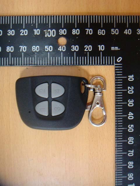
SU7IV318W4K
Oct 29, 2015Remote Controller
Equipment Class
DSC - Part 15 Security/Remote Control Transmitter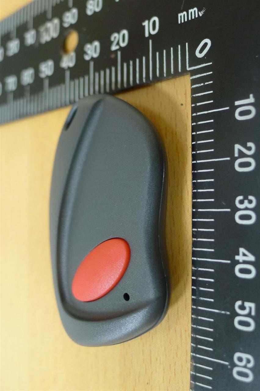
SU7INOX
Sep 30, 2015Remote Controller
Equipment Class
DSC - Part 15 Security/Remote Control Transmitter
SU7DOL433RCP6SQ
Sep 12, 2015Remote Control
Equipment Class
DSC - Part 15 Security/Remote Control Transmitter
SU7DOL433RC6SQ
Sep 12, 2015Remote Control
Equipment Class
DSC - Part 15 Security/Remote Control Transmitter