SU7REATSHECARD READER
Controlled Entry Distributors, Inc.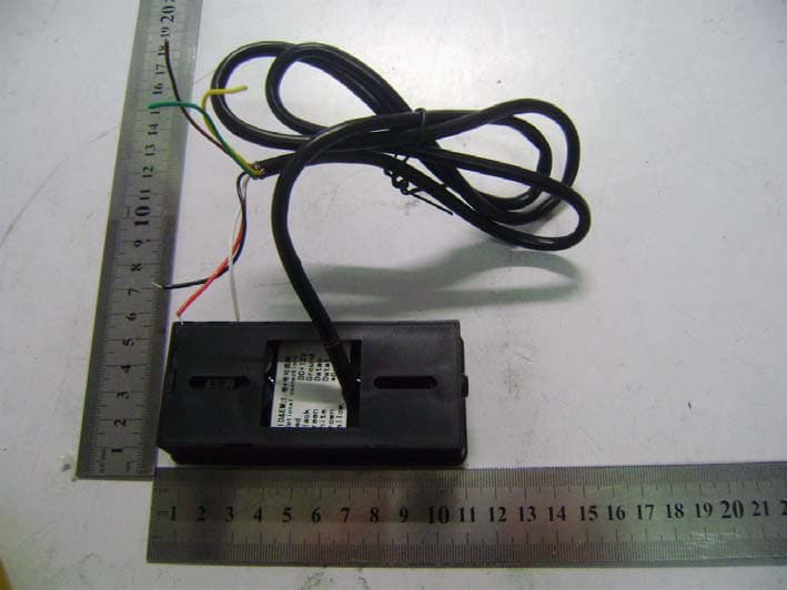
Click to zoom
Application Details
- Equipment Class
- DCD - Part 15 Low Power Transmitter Below 1705 kHz
- Date of Grant
- Mar 08, 2011
- Application Purpose
- Original Equipment
- Date of Application
- Mar 08, 2011
- Equipment Note
- CARD READER
- Frequency Range
- 0.12500000 - 0.12500000
- Country
- United States
Documents & Files
Document Text
Text extracted from the exhibit documents filed with the FCC. Open a document above to read the original.
Users Manual
I/O ALARM- R8 R20 Q6 Lock Interface Principle: By programme setting, I/O switch between low level and high level. 4-low level 5-high level I/O L- L+ +12V R7 R19 Q2 D6 Alarm Interface Principle: when alarm, the I/O outputs high level. The W2 is fully waterproof Proximity stand alone access Reader, which uses advanced microprocessor, equipped with large capacity Flash memory, supports up to 10 000 cards. It is so easy to add or delete card users by using the master card, besides, with Infrared remote control programmer, the user can set the features by themselves, including Alarm, Self-protection, interlock and Anti- submarine back Function. In additional, with infrared remote control programmer, you can add or delete cards directly by inputting card number The W2 not only has the features of low power consumption, automatic selection of lock ,anti vandal alarm and exit button, but also has the protective functions against input over voltage and outputs short-circuit. These features make the W2 safe , reliable and easy in operation. It is an idea choice for door access. 2.Description Standalone Card Reader Use capacity: 10,000 Card interface: 125KHZ EM card Remote control for programming With Manager cards for fast add and delete users Wiegand26 input/output 3.Features 4. Specifications Supply Voltage Sleeping Current Card type Card Reading Distance Wiegand interface Temperature 20%98% Max20A Max20A Two 103*48*23mm Drill holes on the wall or prepare the cassette. Wire through the hole, and blanket the unused cable in case of short circuit. Fix the back cover firmly on the cassette or the wall. Attach the reader to the back cover. 5. Installation 6. Wiring No 1 2 3 4 5 6 7 8 9 10 Color Yellow Blue Brown Purple Grey Red Black White Green Orange Function D0 D1 ALARM+ OPEN D_IN 12V GND VSS L- L+/Alarm+ Description Wiegand output, input signal wire D0 Wiegand output, input signal wire D1 connecting to the negative pole of the alarm equipment To connect to one part of Exit Button Door Contact input (+) 12Vdc Positive Regulated Power Input (-) Negative Regulated Power Input the negative pole of the controller, connect to the other part of Exit button and door contact Connect to the negative pole of the Lock Connect to the positive pole of the lock and alarm equipment Connection Diagram 7. Interface Circuits Figure 1 Note: The above diagrams show the output interface circuits. Do not power on until all wiring has been completed Power off, use the supplied Contact Pin to short out the 2P socket on the mainboard, then power on, if successful, the beeper will beep twice, the LED shines in orange, remove the Short Pin, then read any two EM cards, after that the LED turns in red, means reset to factory default setting successfully. Of the two EM cards read, the first one is Manager add card, the second one is Manager delete card. Remarks: Reset to factory default setting, the users' information enrolled is still retained. When reset to Factory setting, the two Manager cards must be re-enrolled. 8.To Reset to Factory Default and Manager Card setting 9. Sound and Light indication Operation status Reset to factory default setting Sleeping mode Operation successful Enter into programming mode Enter into setting Exist from programming mode Operation failed Open the door Alarm LED Orange Red shines slow Red shines Orange shines Red shines slow Green shines Red shines fast Buzzer Two short ring Short ring Short ring Short ring Short ring Three short ring Short ring Alarm 10. W2 Detailed Programming Guide 10.1User settings There are 2 ways to add and delete users: A - By manager card; B - By remote control A - By Manager card(The most convenient way) To Delete User by Manager Card B- By Remote control Enter into the programming mode firstly To Enter the programming mode Manager add card Read user card Manager add card Cards can be added continuously. Manager delete card Read user card Manager Delete card Cards can be deleted continuously. * Manager Password # 888888 is the default factory master code To Add user by Manager Card Remarks: All the steps below must be done after enter into programming mode To change the master code 0 New Password # Repeat New Password # The master code must be 68 digit number. To add a card user (Method 1) This is the faster way to enter cards using ID number auto generation. The card can be either be presented or input the 8 digit card number from the card can be manually entered 1 Read Card # or 1 Input Card number (8 digit) # Card can be added continuously without exiting programming mode. The card number is the last 8 digits of the number printing on the card. DC12V/3A + - - + Lock - + Exit button Alarm door detecting switch Common Power Supply W2 D0 D1 ALARM- OPEN D_IN +12V GND VSS L- L+ ALARM+ J1 Green White Grey Yellow Brown Red Black Blue Purple Orange D0 ALARM- OPEN D_IN +12V GND VSS L+ ALARM+ J1 DC12V/3A + - COM NC NO PUSH D1 L- Green White Grey Yellow Brown Red Black Blue Purple Orange door detecting switch Exit button Alarm F a i l - s e c u r e l o c k F a i l - s a f e l o c k Special Power Supply W2 - Waterproof Standalone Proximity Reader Shielded cables C D 6 1 m m 9 5 . 5 m m 40mm A B To add a card user(Method 2) This is the alternative way to enter cards using User ID Allocation. In this method a User ID is allocated to a card. Only one user ID can be allocated to a single card. 1 ID number # Read Card # or 1 ID number # the Card number (8 digits) # To delete a card user by card Number. Note users can be deleted continuously without exiting programming mode 2 Read Card # or 2 Card number # To delete ALL users. (Note: This option will delete all users but Manager Cards. Be careful with use) 2 0000 # .4..5..6. Can be used as salve reader 2 pcsW2 can be interconnected/ interlocked Can be used as controller by connection slave reader Anti-submarine back Function Alarm signal output, Door open detection Full of 10000 users, recognizing speed <15ms. 1. Packing List Na…
Text truncated - open the document above for the full version.
External Photos
Controlled Entry Distributors, Inc. Model: R2 REPORT NO.: STR10128125I FCC PART 15C EXHIBIT 2 - EUT EXTERNAL PHOTOGRAPHS EUT View 1 EUT View 2
ID Label/Location Info
Controlled Entry Distributors, Inc. Model: R2 REPORT NO.: STR10128125I FCC PART 15C EXHIBIT 1- PRODUCT LABELING Proposed FCC ID Label Format FCC ID: SU7REATSHE This device complies with Part 15 of the FCC Rules. Operation is subject to the following two conditions: (1) This device may not cause harmful interference, and (2) This device must accept any interference received, including interference that may cause undesired operation. Specifications : Text is Black in color and justified. Labels are printed in indelible ink on permanent adhesive silk-screened onto the EUT or shall be affixed at a conspicuous location on the EUT. Proposed Label Location on EUT FCC ID Label Location
ID Label/Location Info
Controlled Entry Distributors, Inc. Model: R2 REPORT NO.: STR10128125I FCC PART 15C EXHIBIT 1- PRODUCT LABELING Proposed FCC ID Label Format FCC ID: SU7REATSHE This device complies with Part 15 of the FCC Rules. Operation is subject to the following two conditions: (1) This device may not cause harmful interference, and (2) This device must accept any interference received, including interference that may cause undesired operation. Specifications : Text is Black in color and justified. Labels are printed in indelible ink on permanent adhesive silk-screened onto the EUT or shall be affixed at a conspicuous location on the EUT. Proposed Label Location on EUT FCC ID Label Location
Internal Photos
Controlled Entry Distributors, Inc. Model: R2 REPORT NO.: STR10128125I FCC PART 15C EXHIBIT 3 - EUT INTERNAL PHOTOGRAPHS EUT Housing and Board View Solder Board-Component View 1 Controlled Entry Distributors, Inc. Model: R2 REPORT NO.: STR10128125I FCC PART 15C Solder Board-Component View 2 Solder Board-Component View 3 Controlled Entry Distributors, Inc. Model: R2 REPORT NO.: STR10128125I FCC PART 15C Solder Board-Component View 4
Operational Description
R2-H&EM is a card-reader made by two readable cards, HID & EM. After generating sine wave by 125 KHz square-wave throughout the drive circuit & oscillation of antenna, the product will provide EM card-reader circuit and HID card-reader circuit. The clock signal of the 20MHz is base clock frequency. HID card-reader circuit will send signals to HID drive circuit & HID comparison circuit, and then to HID micro controller for decoding. HID micro controller will send out Wiegand 26 signals, EM card-reader circuit will send the received signals to micro controller MCU for comparison & decoding, meanwhile, it will also send out signals by Wiegand 26. The Wiegand 26 signals from HID and EM will be sent to Wiegand driving circuit, and after being enlarged, it will output Wiegand 26 signals, and the signals can be connected with any controllers with the function of Wiegand 26 input. The product can be outputted by Wiegand 26 with buzzer alarm and LED light controlling line, and it is also available when connecting with low input.
Schematics
12345678 A B C D 87654321 D C B A 1 2 3 4 5 6 7 J1 CON7 LED BELL D0 D1 +12V GND GND D1 IN4004 +12V +12V 1 1 2 2 3 3 U1 LM78M05(252S) C1 100u/25V C3 104P L1 100uH C2 100u/25V C4 104P 12V C6 100u/16V C5 104P +5V 12V R6 560R Q1 S8050 R4 10K C7102P R1 1K RF-OUT R7 560R Q2 S8050 Q5 S8550 +5V 1 2 J2 ANT 1 2 J2-1 ANT C8 2A332J D6 IN4148 D4 IN4148 R19 10M C14 202P C15 202P C13 202P C12 202P R18 240K D5 IN4148 C9 220P M-IN L2 490uH 201 192 183 174 165 156 147 138 129 1110 U3 AT89C2051 U2 MAX813 1 2 3 45 6 7 8 +5V WD MR VCC GND PFIPFO WDI RESET WDO RST P30 P31 X1 X2 P32 P33 P34 P35 GND VCC P10 P11 P12 P13 P14 P15 P16 P17 P37 X1 12.0MHz C29 33P C30 33P WD LED +5V RED GREEN SOUND RF-OUT D1 D0 M-IN Date0 Date1 123 SIP1 CON3 RG LED3 LED RG LED7 LED RG LED1 LED RG LED2 LED RG LED8 LED RG LED6 LED RG LED5 LED RG LED4 LED R2 2K R3 2K 12V RG 123 SIP1-1 CON3 12V RG 12V 1 2 3 Q8 S8050 Q10 S8050 R35 30K R37 30K RED GREEN +5V Q11 S8550 B1 AC5V-47R D7 IN4148 R40 10K SOUND 1234567 8910 1112 131415161718 CMP1VREFCMP2VSSTHVINTRX TX CCP1 PGM RB5 OSO OSI VDD OSC1 OSC2 RND AN1 U4 PIC16F628A 12 34567 8 9 10 11 121314 OUT1 OUT2 OUT3 OUT4 IN1- IN2- IN3- IN4- IN1+IN2+ IN3+ IN4+ VCCVSS U6 084C 1234 5678 OUT1 IN1- IN1+ IN2+ IN2- VSS VDDOUT2 U5 LM393 C18 104 R45 10K R41 2.7K C16 47uF C17 104 X2 20.0M C10 22P C11 22P C19 104 R24 10K R20 10K C20 102 R29 15.4K C21 102 R21 10K C23 102 R23 10K R22 10K C27 102 R34 82.5K C26 102 R31 2.67K R30 47.5K C24 102 C25 102 R33 1.82K R32 1M C28 470P C32 202 R42 470K R28 10K R26 10K C22 102 R25 10K C31 104 H-ANT H-ANT +5V +5V +5V +5V R9 10K D1-OUT D0-OUT R15 2K R14 2K R11 200K R8 10K R13 2K R12 2K R10 200K Q7 S8550 Q6 S8550 Q3 S8050 Q4 S8050 R16 2K R17 2K TVS2 22V TVS1 22V Date0 Date1 +5V +5V D0 A0 D1 A1 A0A1 H-R LED BELL 设计: 审核: 批准: 日期: 深圳世礴创科技有限公司 型号:R1,R2-EM&H V0.3.sch 图号: 版本: V0.3 页码: 1 OF 1 文件:R1/2-EM&H V0.3 R431K C34 104 R441K C33 104 BELL H-R R36 100K TVS3 C36C35 D2 IN4148 D3 IN4148 R38 10R Or 0R R? 100K LED NC NC UnRegistered
Test Report
Controlled Entry Distributors, Inc. Model: R2 REPORT NO.: STR10128125I PAGE 1 OF 15 FCC PART 15C FCC PART 15C MEASUREMENT AND TEST REPORT FOR Controlled Entry Distributors, Inc. 2500 South 3850 West, Suite A, Salt Lake City, UT 84120 USA FCC ID: SU7REATSHE Report Concerns: Original Report Equipment Type: Card Reader Model: R2 Report No.: STR10128125I Test Date: 2010-12-19 to 2010-12-23 Issue Date: 2011-03-09 Tested By: Susan Su / Engineer Reviewed By: Lahm Peng / EMC Manager Approved & Authorized By: Jandy so / PSQ Manager Prepared By: SEM.Test Compliance Service Co., Ltd 3/F, Jinbao Commerce Building, Xin'an Fanshen Road, Bao'an District, Shenzhen, P.R.C.(518101) Tel.: +86-755-33663308 Fax.: +86-755-33663309 Website: www.semtest.com.cn Note: This test report is limited to the above client company and the product model only. It may not be duplicated without prior permitted by SEM.Test Compliance Service Co., Ltd . Controlled Entry Distributors, Inc. Model: R2 REPORT NO.: STR10128125I PAGE 2 OF 15 FCC PART 15C TABLE OF CONTENTS 1. GENERAL INFORMATION ...................................................................................................................................3 1.1 PRODUCT DESCRIPTION FOR EQUIPMENT UNDER TEST (EUT)...............................................................................3 1.2 TEST STANDARDS...................................................................................................................................................3 1.3 TEST METHODOLOGY.............................................................................................................................................3 1.4 TEST FACILITY.......................................................................................................................................................4 1.5 EUT EXERCISE SOFTWARE....................................................................................................................................4 1.6 ACCESSORIES EQUIPMENT LIST AND DETAILS.......................................................................................................4 1.7 EUT CABLE LIST AND DETAILS.............................................................................................................................4 2. SUMMARY OF TEST RESULTS ...........................................................................................................................5 3. §15.203 - ANTENNA REQUIREMENT..................................................................................................................6 3.1 STANDARD APPLICABLE.........................................................................................................................................6 3.2 TEST RESULT..........................................................................................................................................................6 4. §15.207 (A)- CONDUCTED EMISSION .................................................................................................................7 4.1 MEASUREMENT UNCERTAINTY..............................................................................................................................7 4.2 TEST EQUIPMENT LIST AND DETAILS.....................................................................................................................7 4.3 TEST PROCEDURE...................................................................................................................................................7 4.4 BASIC TEST SETUP BLOCK DIAGRAM.....................................................................................................................7 4.5 ENVIRONMENTAL CONDITIONS..............................................................................................................................8 4.6 TEST RECEIVER SETUP...........................................................................................................................................8 4.7 SUMMARY OF TEST RESULTS/PLOTS......................................................................................................................8 4.8 CONDUCTED EMISSIONS TEST DATA......................................................................................................................8 5. §15.205, §15.209- RADIATED EMISSION ...........................................................................................................11 5.1 MEASUREMENT UNCERTAINTY............................................................................................................................11 5.2 STANDARD APPLICABLE.......................................................................................................................................11 5.3 TEST EQUIPMENT LIST AND DETAILS...................................................................................................................11 5.4 TEST PROCEDURE.................................................................................................................................................12 5.5 CORRECTED AMPLITUDE & MARGIN CALCULATION............................................................................................12 5.6 ENVIRONMENTAL CONDITIONS............................................................................................................................12 5.7 SUMMARY OF TEST RESULTS/PLOTS....................................................................................................................13 Controlled Entry Distributors, Inc. Model: R2 REPORT NO.: STR10128125I PAGE 3 OF 15 FCC PART 15C 1. GENERAL INFORMATION 1.1 Product Description for Equipment Under Test (EUT) Client Information Applicant: Controlled Entry Distributors, Inc. Address of applicant: 2500 South 3850 West, Suite A, Salt Lake City, UT 84120 USA Manufacturer: Sebury Technology Co., Ltd. Address of manufacturer: 5/F, Building 8, Xinwu Industrial Park, Xili, …
Text truncated - open the document above for the full version.
Test Setup Photos
Controlled Entry Distributors, Inc. Model: R2 REPORT NO.: STR10128125I FCC PART 15C EXHIBIT 4 - TEST SETUP PHOTOGRAPHS Conduction Emission Test Setup Radiation Emission Test Setup (Below 30MHz) Controlled Entry Distributors, Inc. Model: R2 REPORT NO.: STR10128125I FCC PART 15C Radiation Emission Test Setup (Above 30MHz)
Contact Information
Applicant
Bradley C Kofford(President)
Test Firm
SEM.Test Compliance Service Co., Ltd.Jandy So
Technical Specifications
| # | Rule Parts | Frequency Range | Power Output |
|---|---|---|---|
| 1 | 15C | 0.125 MHz - 0.125 MHz | - |
Other Applications from Controlled Entry Distributors, Inc.
SU7318TRS8
Dec 12, 2022Part 15 Security / Remote Control Transmitter
Equipment Class
DSC - Part 15 Security/Remote Control Transmitter
SU7IV318W4K
Oct 29, 2015Remote Controller
Equipment Class
DSC - Part 15 Security/Remote Control Transmitter
SU7INOX
Sep 30, 2015Remote Controller
Equipment Class
DSC - Part 15 Security/Remote Control Transmitter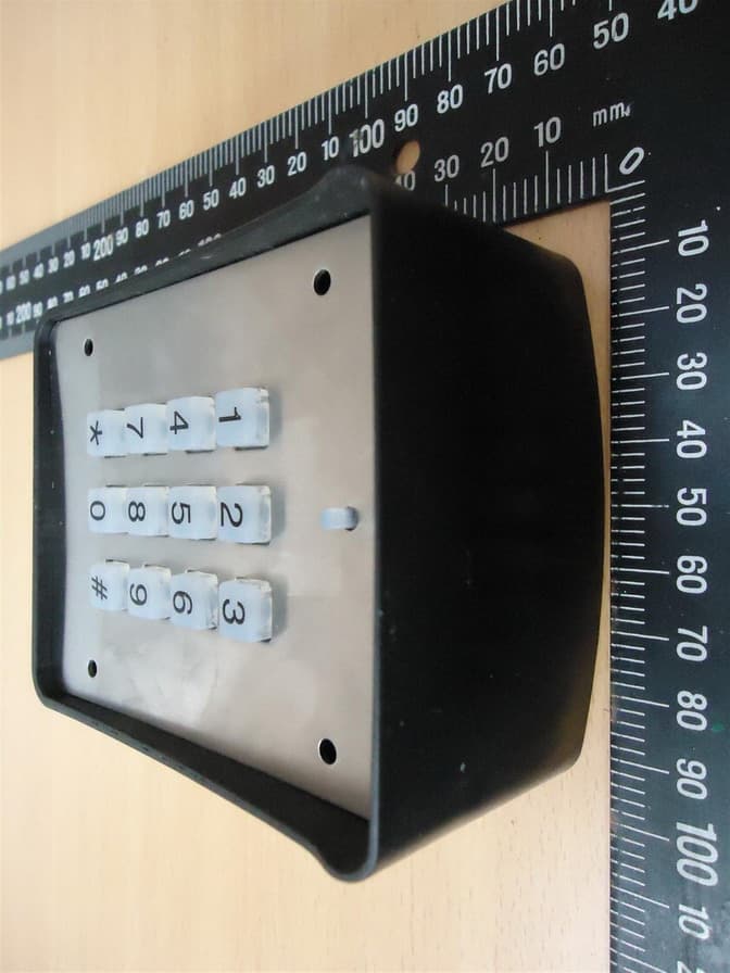
SU7DOL433RCP6SQ
Sep 12, 2015Remote Control
Equipment Class
DSC - Part 15 Security/Remote Control Transmitter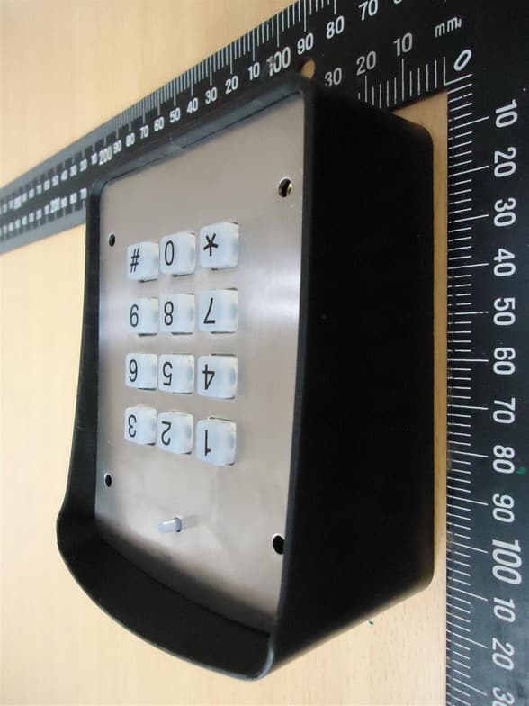
SU7DOL433RC6SQ
Sep 12, 2015Remote Control
Equipment Class
DSC - Part 15 Security/Remote Control Transmitter