SU7SAM1000ACCESS CONTROLS
Controlled Entry Distributors, Inc.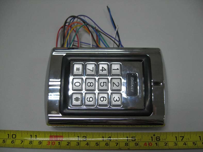
Click to zoom
Application Details
- Equipment Class
- DCD - Part 15 Low Power Transmitter Below 1705 kHz
- Date of Grant
- Feb 26, 2008
- Application Purpose
- Original Equipment
- Date of Application
- Feb 26, 2008
- Equipment Note
- ACCESS CONTROLS
- Frequency Range
- 0.12500000 - 0.12500000
- Country
- United States
Documents & Files
Document Text
Text extracted from the exhibit documents filed with the FCC. Open a document above to read the original.
Users Manual
SEBURY SAM-1000 Digital Keypad 2 Introduction The SAM-1000 uses the latest microprocessor technology to operate door strikes and security systems that require a momentary (timed) or latching dry contact closure. All programming is done through the keypad. Codes and operating parameters are stored within the microprocessor and can not be lost due to power failure. The SAM-1000 can store 1000 prox cards and user 4 digit codes. Each 4 digit code has 10,000 possible combinations. The unit has one relay with 5 Amp contacts. CONTENTS Page Introduction ...................................................................... 2 Product Specifications .......................................................... 3 Intramural Interface Circuit.................................................... Mounting & PCB Diagram .................................................... 4 Wiring Diagram ................................................................ 4-5 Engineer Programming Information and Notes .......................... 5 Engineer Programming Factory Default Setting .................................................. 6 Changing Master & User Codes......................................... 7 Setting Functions of Master & User .................................. 7 Set Door Relay Strike ...................................................... 7 Set Door Open Detection Time ........................................ 8 Security Arrangement .................................................... 9 Exit Engineer Programming Mode .................................... 9 Resetting Non Volatile Memory .............................................. 9 Installer Information & Notes ................................................... 9 Technical Specifications ....................................................... 10 3 Specifications 1. Programmable Functions Relay latching or momentary Relay activate independently or together Change Codes 1 master, 1000 users & prox cards Door open detection 2. Programmable Timers Door relay time 00-99 seconds Door open detection 00-99 seconds Alarm time 00-99 minutes 3. Wiring Connections Electric lock External bell External Push Switch Magnetic Contacts Alarm 4. Keypad: 12 keys 5. Programming memory: Non volatile Eeprom memory IMPORTANT INFORAMTION There are no user serviceable parts contained within the SAM-1000 access control keypad. If holes are to be drilled before mounting onto a wall, check for hidden cables and/or pipes before drilling. Use safety goggles when drilling or hammering in cable clips. Every effort has been made to provide accurate information, however slight variations can occur. We also reserve the right to make changes for product improvement at any time NOTE PLEASE READ THESE INSTRUCTIONS CAREFULLY BEFORE ATTEMPTING TO INSTALL THE SAM-1000 Intramural Interface Circuit 1. Alarm output interface (See Figure 1) 2. Electric lock interface (See Figure 2) 4 Figure 1 Figure 2 Mounting 1. Attach the rear plate to a single or double gang electrical box or secure to the wall firmly with at least three flat head screws. 2. When wiring has been completed, attach the front cover to the rear plate. Figure 3 5 Figure 4 The front cover can be permanently secured by using the short screw supplied SAM-1000 Printed Circuit Board Wiring 1. Unplug the cable harness and connect the necessary cables, (See Figure 5). 2. Tape any wires that are unused. 3. Plug the cable harness , (See Figure 5) 4. Attach the front cover, (See Figure 3). Terminal Wire Connector 1 Function 10 Bell1 White Bell Push Button 9 Bell2 White Bell Push Button 8 12V Red (+) 12Vdc Positive Regulated Power Input 7 GND Black (-) Negative Regulated Power Input 6 COM Orange Door Strike Relay Com 5 NO Blue Door Strike Relay N/O 4 NC Green Door Strike Relay N/C 3 D_IN Brown To Door Contact Then To Door In 2 OPEN Yellow To Door Remote Control Button Then Negative 1 ALARM Grey Alarm Warning! Do not plug adaptor our transformer into mains until all wiring has been completed and the front cover secured. 6 Figure 5 Power Up 1. After all wiring is complete and the unit face plate is attached to the back plate, apply 12Vdc power to the unit. Accept LED(the yellow LED) flashing. Engineer Programming Mode To enter programming mode Press: * 9999 # within 5 seconds, Ready(the green LED) and Accept LED illuminated, Open LED flashing. Note Press: # to save changes and exit engineer programming, when all programming has been completed otherwise changes will not be saved. Changing Master & User Codes In engineer programming mode: To change Master code Press: 0 new master code # re-enter new master code # 7 Upon acceptance Open LED illuminates and stops flashing. Press * after changing the master code, otherwise unit will disregard the new code and revert back to the factory default code. Note: the master code must be 4-8 digit number. Adding User Codes & Cards To Add User cards & codes Press: 1 read card user identification # Note: the user identification must be 3 digit number, if adding more than 1 card, read the next card after inputting the 3 digit code for the previous card, when you have finished adding all cards press the # key. 1 st card must be 000 up to 999. Then the SAM-1000 control station added a user card it was auto added a user code with 1234. Delete User Card or Cards There are 3 options to delete a user card or cards, in engineering mode. a.) Press: 2 0 0 0 0 # to delete all user cards b.) Press: 2 read card # to delete individual user card c.) Press: 2 user identification number # to delete individual user card User Operation Mode There are 3 different options for user operation mode, card only, card and password, valid code. The optioned used is common to all users. Press: 3 0 0 # valid card only Press: 3 0 1 # valid card and password Press: 3 0 2 # valid card or password Setting Door Relay Strike Time The door relay output can be operated as either normally opened or normally closed, a maximum current of 10 ampere can p…
Text truncated - open the document above for the full version.
External Photos
CONTROLLED ENTRY DISTRIBUTOR, INC. Model: SAM-1000 Report No.: STR08018060I FCC PART 15C EXHIBIT 2 - EUT EXTERNAL PHOTOGRAPHS EUT View 1 EUT View 2
ID Label/Location Info
CONTROLLED ENTRY DISTRIBUTOR, INC. Model: SAM-1000 Report No.: STR08018060I FCC PART 15C EXHIBIT 1- PRODUCT LABELING Proposed FCC Label Format FCC ID: SU7SAM1000 Specifications : Labels are printed in indelible ink on permanent adhesive silk-screened onto the EUT or shall be affixed at a conspicuous location on the EUT. Proposed Label Location on EUT FCC Label Location
ID Label/Location Info
CONTROLLED ENTRY DISTRIBUTOR, INC. Model: SAM-1000 Report No.: STR08018060I FCC PART 15C EXHIBIT 1- PRODUCT LABELING Proposed FCC Label Format FCC ID: SU7SAM1000 Specifications : Labels are printed in indelible ink on permanent adhesive silk-screened onto the EUT or shall be affixed at a conspicuous location on the EUT. Proposed Label Location on EUT FCC Label Location
Internal Photos
CONTROLLED ENTRY DISTRIBUTOR, INC. Model: SAM-1000 Report No.: STR08018060I FCC PART 15C EXHIBIT 3 - EUT INTERNAL PHOTOGRAPHS EUT Housing and Board View 1 Solder Board-Component View 1 CONTROLLED ENTRY DISTRIBUTOR, INC. Model: SAM-1000 Report No.: STR08018060I FCC PART 15C Solder Board-Component View 2
Operational Description
Operational Descriptions The signal is detected from the 125kHz antenna RF module, then the signal is analyzed by the CPU(AT89S52) which is supported by 12MHz crystal. Then the functional control signal is active to the Buzzer. CPU is powered by 12v together with the filter of LM7805.
Test Report
CONTROLLED ENTRY DISTRIBUTOR, INC. MODEL: SAM-1000 REPORT NO.: STR08018060I PAGE 1 OF 13 FCC PART 15C FCC PART 15C MEASUREMENT AND TEST REPORT FOR Controlled Entry Distributor, Inc. 2500 South 3850 West, Suite A, Salt Lake City, Utah 84120 USA FCC ID: SU7SAM1000 Report Concerns: Original Report Equipment Type: Access controls Model: SAM-1000 Report No.: STR08018060I Test/Witness Engineer: Test Date: 2008-01-18 to 2008-01-24 Prepared By: Shenzhen SEM.Test Compliance Service Co., Ltd. 3/F, Jinbao Commerce Building, Xin'an Fanshen Road, Bao'an District, Shenzhen, P.R.C. (518101) Approved & Authorized By: Jandy So / PSQ Manager Note: This test report is limited to the above client company and the product model only. It may not be duplicated without prior permitted by SEM.Test Compliance Service Co., Ltd . CONTROLLED ENTRY DISTRIBUTOR, INC. MODEL: SAM-1000 REPORT NO.: STR08018060I PAGE 2 OF 13 FCC PART 15C TABLE OF CONTENTS 1. GENERAL INFORMATION ...................................................................................................................................3 1.1 PRODUCT DESCRIPTION FOR EQUIPMENT UNDER TEST (EUT)...............................................................................3 1.2 TEST STANDARDS...................................................................................................................................................3 1.3 RELATED SUBMITTAL(S)/GRANT(S) .......................................................................................................................3 1.4 TEST METHODOLOGY.............................................................................................................................................3 1.5 TEST FACILITY.......................................................................................................................................................4 1.6 EUT EXERCISE SOFTWARE....................................................................................................................................4 1.7 ACCESSORIES EQUIPMENT LIST AND DETAILS.......................................................................................................4 1.8 EUT CABLE LIST AND DETAILS.............................................................................................................................4 2. SUMMARY OF TEST RESULTS ...........................................................................................................................5 3. §15.107 (A)- CONDUCTED EMISSION .................................................................................................................6 3.1 MEASUREMENT UNCERTAINTY..............................................................................................................................6 3.2 TEST EQUIPMENT LIST AND DETAILS.....................................................................................................................6 3.3 TEST PROCEDURE...................................................................................................................................................6 3.4 BASIC TEST SETUP BLOCK DIAGRAM.....................................................................................................................6 3.5 ENVIRONMENTAL CONDITIONS..............................................................................................................................7 3.6 TEST RECEIVER SETUP...........................................................................................................................................7 3.7 SUMMARY OF TEST RESULTS/PLOTS......................................................................................................................7 3.8 CONDUCTED EMISSIONS TEST DATA......................................................................................................................7 4. §15.109(A) - RADIATED EMISSION ...................................................................................................................10 4.1 MEASUREMENT UNCERTAINTY............................................................................................................................10 4.2 TEST EQUIPMENT LIST AND DETAILS...................................................................................................................10 4.3 TEST PROCEDURE.................................................................................................................................................10 4.4 TEST RECEIVER SETUP.........................................................................................................................................11 4.5 CORRECTED AMPLITUDE & MARGIN CALCULATION............................................................................................11 4.6 ENVIRONMENTAL CONDITIONS............................................................................................................................11 4.7 SUMMARY OF TEST RESULTS/PLOTS....................................................................................................................12 CONTROLLED ENTRY DISTRIBUTOR, INC. MODEL: SAM-1000 REPORT NO.: STR08018060I PAGE 3 OF 13 FCC PART 15C 1. GENERAL INFORMATION 1.1 Product Description for Equipment Under Test (EUT) Client Information Applicant: Controlled Entry Distributor, Inc. Address of applicant: 2500 South 3850 West, Suite A, Salt Lake City, Utah 84120 USA Manufacturer: Sebury Technology Co., Ltd. Address of manufacturer: Zhuangda Industrial park, Fuguang Village, Xili Town, Nanshan District, Shenzhen City, Guangdong Province, China General Description of E.U.T Items Description EUT Description: Access controls Trade Name: / Model No.: SAM-1000 Rated Voltage: DC 12V Rated Current: 0.1mA Operation Frequency: 125kHz Packaging Size: 12.5X7.9X2.6 cm For more information refer to the circuit diagram form and the user’s manual. The test data is gathered from a production sample, provided by…
Text truncated - open the document above for the full version.
Test Setup Photos
CONTROLLED ENTRY DISTRIBUTOR, INC. Model: SAM-1000 Report No.: STR08018060I FCC PART 15C EXHIBIT 4 - TEST SETUP PHOTOGRAPHS Radiation Emission Test Setup
Contact Information
Applicant
Bradley C Kofford(President)
Test Firm
Solid Industrial Co., Ltd.Yang Dengfang
Technical Specifications
| # | Rule Parts | Frequency Range | Power Output |
|---|---|---|---|
| 1 | 15C | 0.125 MHz - 0.125 MHz | - |
Other Applications from Controlled Entry Distributors, Inc.
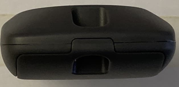
SU7318TRS8
Dec 12, 2022Part 15 Security / Remote Control Transmitter
Equipment Class
DSC - Part 15 Security/Remote Control Transmitter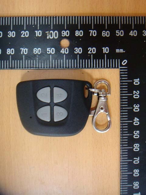
SU7IV318W4K
Oct 29, 2015Remote Controller
Equipment Class
DSC - Part 15 Security/Remote Control Transmitter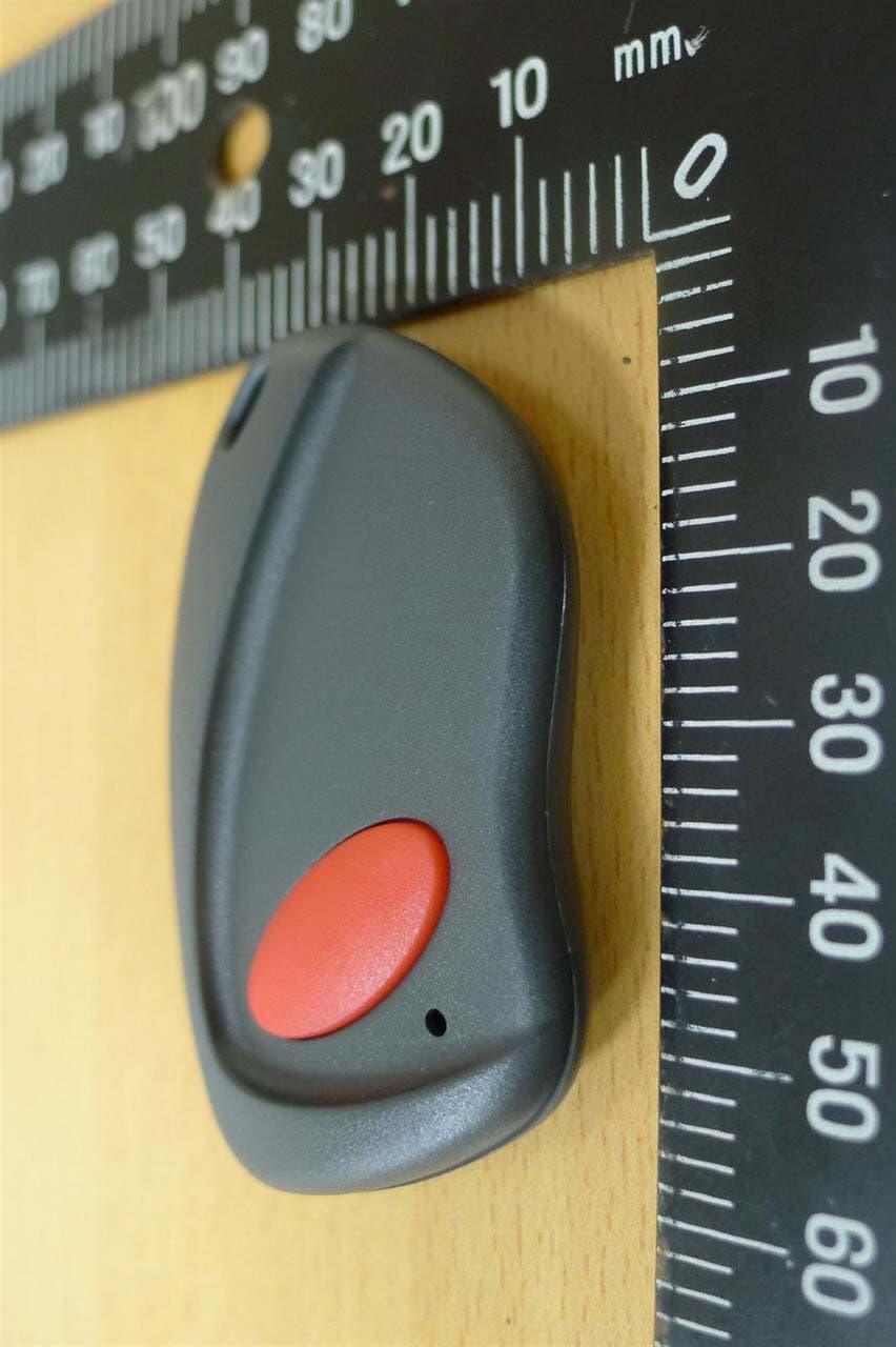
SU7INOX
Sep 30, 2015Remote Controller
Equipment Class
DSC - Part 15 Security/Remote Control Transmitter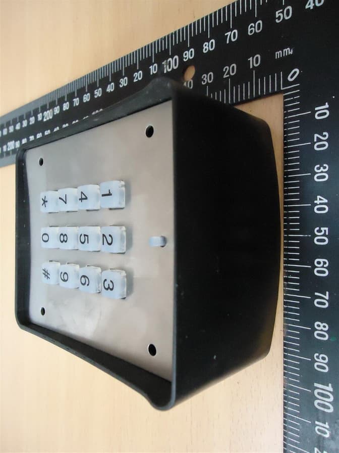
SU7DOL433RCP6SQ
Sep 12, 2015Remote Control
Equipment Class
DSC - Part 15 Security/Remote Control Transmitter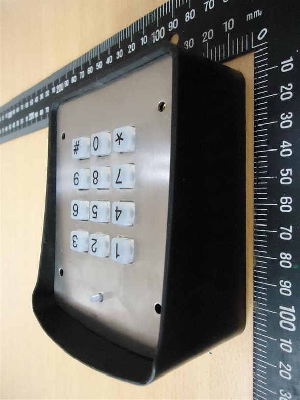
SU7DOL433RC6SQ
Sep 12, 2015Remote Control
Equipment Class
DSC - Part 15 Security/Remote Control Transmitter