SU7SK1-HAccess Control
Controlled Entry Distributors, Inc.
Click to zoom
Application Details
- Equipment Class
- DXX - Part 15 Low Power Communication Device Transmitter
- Date of Grant
- Sep 19, 2013
- Application Purpose
- Original Equipment
- Date of Application
- Sep 19, 2013
- Equipment Note
- Access Control
- Frequency Range
- 0.12500000 - 0.12500000
- Country
- United States
Documents & Files
Document Text
Text extracted from the exhibit documents filed with the FCC. Open a document above to read the original.
Users Manual
SK1-H Waterproof Access Control/Reader User Manual 2 INTRODUCTION The SK1-H is a single- entry multi-function Access Controller with integrated keypad and card reader. It is designed and manufactured to perform in a wide range of indoor, outdoor, and harsh environments. The SK1 supports up to 1000 users in multiple access configurations (Card, Card or PIN, or Card + PIN). The built in card reader supports HID 125KHz frequency cards. The relay can operate in Pulse Mode (suitable for access control) or Toggle Mode (suitable for arming/disarming alarms, switching lights, machines....etc) The SK1-H offers advanced programming features like: Duress PIN/card; Block enrollment; Wiegand 26~37 bits interface. These features make it an ideal choice for door access not only for small shops and domestic households but also for commercial and industrial applications such as factories, warehouses, laboratories, banks and prisons. Features Waterproof, meets IP66 Vandal Resistant Metal Enclosure One Programmable Relay Output Stand Alone or Pass-Through Operation 1000 Users (Card/ Card or PIN /Card+PIN) 10 Panic Card/PIN Codes Latch Mode to hold door or gate open Wiegand 26~37 bits input & output Card Block enrollment Integrated Alarm Buzzer & Output Low power consumption (55mA) Anti-Tamper Alarm Backlit Keypad Multi-color LED status display 12-24V DC/ 12-18V AC Power input Specifications: User Capacity Normal User Panic User 1010 Cards/PINS 1000 10 Operating Voltage Idle Current Active Current 12~24V DC/ 12-18V AC 55mA 80mA Keypad PIN length 12 Key (3*4) 4-6 digits Proximity Card Reader Radio Technology Read Range HID 125KHz Industry Standard Proximity Card 3- 6cm Wiring Connections Electric Lock, Exit Button, DOTL, External Alarm, Wiegand (in/out) Relay Adjustable Relay Output Time ONE (NO, NC, COM) 1-99 Seconds (5 seconds default) 3 Carton Inventory SK1-H Access Controller Self Tapping Screws Wall Anchors Screw Driver Diode IN4004 (For relay circuit protection) Manager Card INSTALLATION Install Remove the back cover from the unit Drill 2 holes(A,C) on the wall for the screws and one hole for the cable Knock the supplied rubber bungs to the screw holes(A,C) Fix the back cover firmly on the wall with 4 flat head screws Thread the cable through the cable hole(B) Adjustable Alarm Output Time Lock Output Load Alarm Output Load 0-3 minutes (1 minute default) 3 Amp Maximum 3 Amp Maximum Wiegand Interface Wiegand 26-37 bit input/output Environment Operating Temperature Operating Humidity Meets IP66 -30°C ~60°C, or -22°F ~ 140°F 10% ~ 90% Non-Condensing Physical Surface Finish Dimensions Unit Weight Shipping Weight Zinc-Alloy Enclosure Powder Coat L: 120* W: 76 * H: 25 (mm) 600g 700g 4 Attach the unit to the back cover. Wiring Wire Color Function Notes Basic Standalone Wiring Red AC&DC 12~24V DC/ 12-18V AC Regulated Power Input Black AC&DC 12~24V DC/ 12-18V AC Regulated Power Input Pink GND Negative Pole Blue NO Normally Open Relay output Purple COM Common Connection for Relay output Orange NC Normally closed Relay Output Yellow OPEN Request to Exit Button Advanced Input and Output Features Green D0 Wiegand Input/Output Data 0 White D1 Wiegand Input/Output Data 1 Grey Alarm - Alarm Negative Brown D_IN Door status detecting Connection Diagram Common Power Supply 5 Access Control Power Supply To Reset to Factory Default To reset to factory default, power off, press * , hold it and power on, release it until hear two beeps and the LED shines in orange, then read any two HID cards, the LED will turn in red, means reset to factory default setting successfully. Of the two HID cards read, the first one is Manager Add Card, the second one is Manager Delete Card. Remarks: Reset to factory default, the user’s information is still retained. Anti Tamper Alarm The SK1-H uses a LDR (light dependent resistor) as an anti tamper alarm. If the keypad is removed from the cover then the tamper alarm will operate. Sound and Light Indication Operation Status Red Light Green Light Yellow Light Buzzer Power on Bright - - Short Ring Stand by Bright - - - Press keypad - - - Short Ring Operation successful - Bright - Short Ring Operation failed - - - 3 Short Rings Enter into programming mode Bright - - Short Ring In the programming mode - - Bright - Exit from the programming mode Bright - - Short Ring Open the door - Bright - Short Ring Alarm Bright - - Alarm 6 Standalone Operation 1.1 User Settings To enter the programming mode * Master code # 666666 is the default factory master code To exit from the programming mode * Note that to undertake the following programming the master user must be logged in To change the master code 0 New code # New code # The master code is any 6 digits Setting the working mode: Set valid card or PIN users Set valid card and PIN users Set valid card only users 3 0 # Entry by either card or PIN (default) 3 1 # Entry by card and PIN together 3 2 # Entry by card only To set a user in either card or PIN mode ( 3 0 # ) (Default setting) To add a PIN user 1 User ID number # PIN # The ID number is any number between 1~1000. The PIN is any 4~6 digits between 0000~999999 with the exception of 1234 which is reserved. Users can be added continuously without exiting from programming mode as follows: 1 User ID no 1 # PIN # User ID no 2 # PIN # To delete a PIN user 2 User ID number # Users can be deleted continuously without exiting programming mode To change the PIN of a PIN user (This step must be done out of programming mode) * ID number # Old PIN # New PIN # New PIN # To add a card user (Method 1) This is the fastest way to add cards using ID number auto generation. 1 Read card # Cards can be added continuously without exiting programming mode To add a card user (Method 2) This is the alternative way to add cards using User ID Allocation. In this method a User ID is allocated to a card. Only one user ID can be allocated to a single card. 1 ID number # Card # To add card user …
Text truncated - open the document above for the full version.
Cover Letter(s)
Controlled Entry Distributors, Inc. FCC Confidentiality Request Number: CF303 Version: V05 Date: 21-05-2012 (Permanent or also called long term confidentiality is the normal method to keep certain docuements confidential, and may apply to schematics, block diagrams, operational description and bill of materials.) To: Federal Communications Commission Equipment Authorization Branch 7435 Oakland Mills Road Columbia, MD 21046 Pursuant to 47 CFR Section 0.459(a) & (b), we, (the applicant / grantee) Company name Controlled Entry Distributors, Inc. Address 2500 South 3850 West, Suite A, City Salt Lake Cit y, UT 84120 Country US A request for this certification filing under: Grantee Code Product Number FCC ID: SU7 SK1-H to maintain permanent confidentiality for the following documents submitted within this application: (please cross what is applicable, or add other documents, provide the file name and description) Exhibit File Name Description √ Operational Description Operational Description explaining the functioning of the block diagram √ Block Diagrams Block Diagrams showing the systematic building blocks of the EUT √ Schematics Diagrams Schematics showing components, their values and interconnection Bill of Materials List of components used on the PCB’s of the EUT Above materials crossed contain secrets, proprietary and technical information, which would customarily be guarded from competitors under 47 CFR, section 0.457(d)(2). Disclosure or publication or any portion of this company confidential material to other parties could cause substantial competitive harm and provide unjustified benefits for competitors. We understand that pursuant to 47 CFR section 0.457(d)(1)(ii) disclosure of the applicant and all accompanying documentation will not be made before the date of the grant. The documents indicated as confidential above, are not publicly available elsewhere. Attestation: City and Country: Date: Name: (this must be a person) Function:Signature: (or official company stamp) Salt Lake City, USA 2013-09-09 Bradley KoffordPresident
Cover Letter(s)
FCC Authorization Letter Number: CF304 Version: V03 Date: 01-08-2011 Controlled Entry Distributors, Inc. We, (the approval holder) Company name Address City Country Controlled Entry Distributors, Inc. 2500 South 3850 West, Suite A, Salt Lake City, UT 84120 USA declare that the following representative (agent): Name (person) Company name Addresss City Country Tom Chen Shenzhen Anbotek Compliance Laboratory Limited 1/F., Building 1, SEC Industrial Park, No.0409 Qianhai Road, Nanshan District, Shenzhen China is hereby authorized to apply the following equipment for certification on our behalf: Product Description Access Control Type or Model(s) SK1-H, K1 Tradename or Brand(s) N/A We also authorize Teleconformity (Mr. M. Koop, Manager Certification, Address: Rietven 31, 7534NH Enschede, the Netherlands) to apply and sign this application for certification, registration or filing on our behalf (as representative agent or certifier). Attestation: City and Country: Date: Name: (this must be a person) Function: Signature: (or official company stamp) Lake City, USA 2013-09-09 Bradley Kofford 7V/,/ Salt President
External Photos
Figure 1 The EUT-Front View Figure 2 The EUT-Back View
ID Label/Location Info
Label Location On EUT
ID Label/Location Info
Product Name: Access Control Model No.: SK1-H FCC ID: SU7SK1-H This device complies with Part 15 of the FCC Rules. Operation is subject to the following two conditions: (1) This device may not cause harmful interference, and (2) This device must accept any interference received, including interference that may cause undesired operation.
Internal Photos
Figure 3 The EUT-Inside View Figure 4 PCB of the EUT-Front View Antenna Figure 5 PCB of the EUT-Back View
Test Report
Shenzhen Anbotek Compliance Laboratory Limited FCC ID: SU7SK1-H Page 1 of 19 Report No.: 201308723F Shenzhen Anbotek Compliance Laboratory Limited Tel: (86)755-26066544 Fax: (86)755-26014772 www.anbotek.com FCC TEST REPORT for Controlled Entry Distributors, Inc. Access Control Model No.: SK1-H, K1 Prepared for : Controlled Entry Distributors, Inc. Address : 2500 South 3850 West, Suite A, Salt Lake City, UT 84120 USA Prepared By : Shenzhen Anbotek Compliance Laboratory Limited Address : 1/F., Building 1, SEC Industrial Park, No.0409 Qianhai Road, Nanshan District, Shenzhen, Guangdong, China Tel: (86) 755-26066544 Fax: (86) 755-26014772 Report Number : 201308723F Date of Test : Aug. 26~ Sep. 03, 2013 Date of Report : Sep. 03, 2013 Shenzhen Anbotek Compliance Laboratory Limited FCC ID: SU7SK1-H Page 2 of 19 Report No.: 201308723F Shenzhen Anbotek Compliance Laboratory Limited Tel: (86)755-26066544 Fax: (86)755-26014772 www.anbotek.com TABLE OF CHONTENTS Description Page Test Report Verification 1. GENERAL INFORMATION ............................................................................................................ 4 1.1. Description of Device (EUT) ..........................................................................................................................4 1.2. Description of Test Facility .............................................................................................................................5 1.3. Measurement Uncertainty ...............................................................................................................................5 2. TEST PROCEDURE ............................................................................................................................. 6 3.POWER LINE CONDUCTED MEASUREMENT ............................................................................. 7 3.1. Block Diagram of Test Setup ..........................................................................................................................7 3.2. Power Line Conducted Emission Measurement Limits (FCC Part 15 15.207) ...............................................7 3.3. Configuration of EUT on Measurement ..........................................................................................................7 3.4. Operating Condition of EUT ...........................................................................................................................7 3.5. Test Procedure .................................................................................................................................................8 3.6. Power Line Conducted Emission Measurement Results .................................................................................8 4. RADIATED EMISSION MEASUREMENT ..................................................................................... 11 4.1. Radiated Emission Limits .............................................................................................................................11 4.2. Test Procedure ...............................................................................................................................................11 4.3. Test Setup ......................................................................................................................................................12 4.4. Test Results (Below 30MHz) ........................................................................................................................14 5.5. Test Results (Between 30-1000MHz) ...........................................................................................................14 APPENDIX I (External Photos) (1 Pages) APPENDIX II (Internal Photos) (2 Pages) Shenzhen Anbotek Compliance Laboratory Limited FCC ID: SU7SK1-H Page 3 of 19 Report No.: 201308723F Shenzhen Anbotek Compliance Laboratory Limited Tel: (86)755-26066544 Fax: (86)755-26014772 www.anbotek.com TEST REPORT VERIFICATION Applicant : Controlled Entry Distributors, Inc. Manufacturer : Secukey Technology Co., Ltd EUT : Access Control Model No. : SK1-H, K1 Rating : DC 12-24V, 55mA or AC 12-18V, 55mA Trade Mark : N/A Measurement Procedure Used: FCC Rules and Regulations Part 15 Subpart C 15.207&15.209-2011 & FCC / ANSI C63.4-2009 The device described above is tested by Shenzhen Anbotek Compliance Laboratory Limited To determine the maximum emission levels emanating from the device. The maximum emission levels are compared to the FCC Part 15 Subpart C limits both radiated and conducted emissions. The measurement results are contained in this test report and Shenzhen Anbotek Compliance Laboratory Limited Is assumed full responsibility for the accuracy and completeness of these measurements. Also, this report shows that the Equipment Under Test (EUT) is to be technically compliant with the FCC requirements. This report applies to above tested sample only. This report shall not be reproduced in part without written approval of Shenzhen Anbotek Compliance Laboratory Limited. Date of Test : Aug. 26~ Sep. 03, 2013 Prepared by : (Engineer/ Rock Zeng) Reviewer : (Project Manager/ Sally Zhang) Approved & Authorized Signer : (Manager/ Tom Chen) Shenzhen Anbotek Compliance Laboratory Limited FCC ID: SU7SK1-H Page 4 of 19 Report No.: 201308723F Shenzhen Anbotek Compliance Laboratory Limited Tel: (86)755-26066544 Fax: (86)755-26014772 www.anbotek.com 1. GENERAL INFORMATION 1.1. Description of Device (EUT) Description : Access Control Model Number : SK1-H, K1 (Note: All samples are the same except the model number & appearance, so we prepare “SK1-H” for EMC test only.) Test Power Supply : DC 12V Frequency : 125KHz Applicant : Controlled Entry Distributors, Inc. Address : 2500 South 3850 West, Suite A, Salt Lake City, UT 84120 USA Manufacturer : Secukey Technology Co., Ltd Address : 3/F, Building 8, Xintang Industrial Park, Fuyong, Bao’an District, Shenzhen, China Date of Sample received : Aug. 26, 2013…
Text truncated - open the document above for the full version.
Test Setup Photos
1. Photo of Conducted Emission Test 2. Photo of Radiated Emission Test
Contact Information
Applicant
Bradley C Kofford(President)
Technical Contact
Test Firm
Shenzhen Anbotek Compliance Laboratory LimitedDaniel zhu
[email protected]86-755-26014771
Technical Specifications
| # | Rule Parts | Frequency Range | Power Output |
|---|---|---|---|
| 1 | 15C | 0.125 MHz - 0.125 MHz | - |
Other Applications from Controlled Entry Distributors, Inc.
SU7318TRS8
Dec 12, 2022Part 15 Security / Remote Control Transmitter
Equipment Class
DSC - Part 15 Security/Remote Control Transmitter
SU7IV318W4K
Oct 29, 2015Remote Controller
Equipment Class
DSC - Part 15 Security/Remote Control Transmitter
SU7INOX
Sep 30, 2015Remote Controller
Equipment Class
DSC - Part 15 Security/Remote Control Transmitter
SU7DOL433RCP6SQ
Sep 12, 2015Remote Control
Equipment Class
DSC - Part 15 Security/Remote Control Transmitter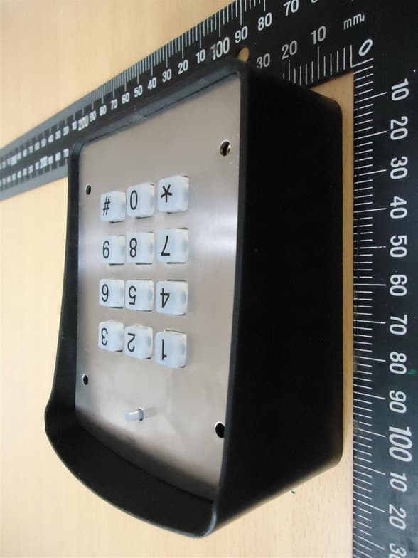
SU7DOL433RC6SQ
Sep 12, 2015Remote Control
Equipment Class
DSC - Part 15 Security/Remote Control Transmitter