SU7TRADCS433Community Controls Handicap Plate Transmitter
Controlled Entry Distributors, Inc.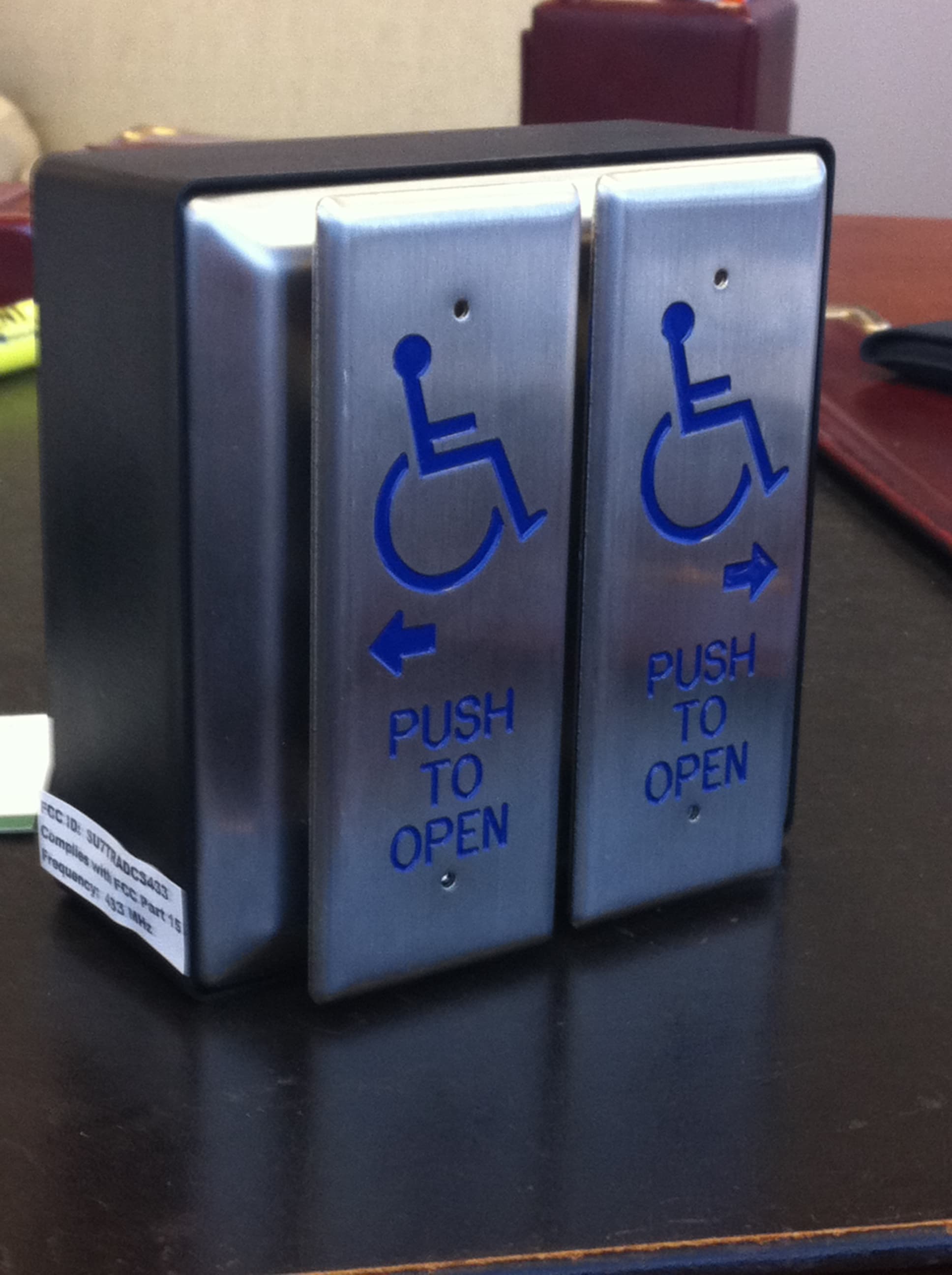
Click to zoom
Application Details
- Equipment Class
- DSC - Part 15 Security/Remote Control Transmitter
- Date of Grant
- Feb 15, 2011
- Application Purpose
- Original Equipment
- Date of Application
- Feb 15, 2011
- Equipment Note
- Community Controls Handicap Plate Transmitter
- Frequency Range
- 433.90000000 - 433.90000000
- Country
- United States
Documents & Files
Document Text
Text extracted from the exhibit documents filed with the FCC. Open a document above to read the original.
Users Manual
Extra-Small Receiver Installation Read this manual carefully before installing any transmitter or receiver. Complete the programming procedure before installing the receiver in its final location. The installer will need to have access to the receiver's programming button and must be able to view the receiver's LED light during the program- ming process. System The Extra-Small Transmitters and Receivers operate at 433.92 MHz and use code-hopping technology. The receiver will only operate with learned transmitters’ signal (see programming transmitter instruc- tions). Installation NOTE: Complete the programming instructions before installing the receiver in its final location. Install the receiver in a location so that the antenna is not surrounded by metal. Metal may cause a reduc- tion in range and inconsistency of signal reception. Door operator motors and power supplies may also cause radio frequency interference. If the receiver is installed in a metal enclosure, drill a hole in the enclosure and thread as much of the antenna as possible through the hole. This will reduce the effects the metal has on the receiver's reception. The receiver comes equipped with a wiring harness for easy installation. Receiver Wiring Harness: Orange Wire: Normally Open Relay Output Brown wire with White Stripe: Normally Open Relay Output Common Connection Red Wire: 24VACl24VDC Power Black Wire: Ground Purple Wire: 12 VACl12VDC Power Brown Wire: Normally Closed Relay Output Common Connection Yellow Wire: Normally Closed Relay Output Programming Instructions: NOTE: Prior to programming, ensure the receiver's LED light blinks red when power is applied. If the LED is not blinking red, disconnect and then reconnect the power. Programming transmitter(s) into the receiver's memory: The receiver can learn up to 12 transmitters. Follow the steps below to program your receiver(s). 1. Press the receiver's programming button for less than 2 seconds and release. The LED should change from blinking red to solid green. The receiver has entered programming mode. 2. Press and release the transmitter once and ensure that the receiver's LED changes to solid red. The receiver is learning the transmitter's code. 3. Wait a few seconds and then press the transmitter button again. The receiver's LED should now blink green several times. It has ended its learning procedure. The LED should now be blinking red. Exterior: Interior: Programming Button Specifications: Transmitter Frequency: 433.92 MHz Dimensions: 1.25 x .875 x .25” Security Code Method: Code Hopping Battery Life: 60,000 cycles Operating Temperatures: -4°F to 122°F Receiver Frequency: 433.92 MHz Dimensions: 2.25 x 1.25 x .75” Security Code Method: Code Hopping, up to 12 transmitters Operating Temperatures: -4°F to 122°F Electrical Rating: 100,000 cycles at 2 Amps. 24 VDC/120 VAC Input Power: 24 VAC, 24 VDC or 12 VAC, 12VDC Output: 2 relay outputs: 1 NO 1 NC Programming the receivers output activation time: When the receiver is activated, its outputs will stay in the minimum activation state for approximately 1.5 seconds (default). This time can be adjusted to stay in the activation state for up to 4 hours. See below to adjust the receiver's output activation time. 1. Press the receiver's programming button for 4 seconds and release. The LED should be solid red. The receiver is in the activation time programming mode. 2. Press and release the transmitter button. 3. When the desired time has elapsed (up to 4 hours) press the transmitter button again. The receiver's LED should blink green several times. When the procedure has ended, the LED should be blinking red. Deleting transmitters from the receiver's memory: See below to erase the receiver's memory of all previously learned transmitters. NOTE: Deleting previously learned transmitters does not change the receiver's output activation time. 1. Press the receiver's programming button for at least 8 seconds until the receiver's LED starts blinking green, then release the programming button. The LED should now be blinking red. 2. The receiver's memory is now cleared. FCC ID: SU7TRADCS433 Changes or modifications not expressly approved by the party responsible for compliance could void the user’s authority to operate the equipment.
Internal Photos
Front View of EUT Back View of the EUT
Operational Description
Extra-Small Receiver Installation Read this manual carefully before installing any transmitter or receiver. Complete the programming procedure before installing the receiver in its final location. The installer will need to have access to the receiver's programming button and must be able to view the receiver's LED light during the program- ming process. System The Extra-Small Transmitters and Receivers operate at 433.92 MHz and use code-hopping technology. The receiver will only operate with learned transmitters’ signal (see programming transmitter instruc- tions). Installation NOTE: Complete the programming instructions before installing the receiver in its final location. Install the receiver in a location so that the antenna is not surrounded by metal. Metal may cause a reduc- tion in range and inconsistency of signal reception. Door operator motors and power supplies may also cause radio frequency interference. If the receiver is installed in a metal enclosure, drill a hole in the enclosure and thread as much of the antenna as possible through the hole. This will reduce the effects the metal has on the receiver's reception. The receiver comes equipped with a wiring harness for easy installation. Receiver Wiring Harness: Orange Wire: Normally Open Relay Output Brown wire with White Stripe: Normally Open Relay Output Common Connection Red Wire: 24VACl24VDC Power Black Wire: Ground Purple Wire: 12 VACl12VDC Power Brown Wire: Normally Closed Relay Output Common Connection Yellow Wire: Normally Closed Relay Output Programming Instructions: NOTE: Prior to programming, ensure the receiver's LED light blinks red when power is applied. If the LED is not blinking red, disconnect and then reconnect the power. Programming transmitter(s) into the receiver's memory: The receiver can learn up to 12 transmitters. Follow the steps below to program your receiver(s). 1. Press the receiver's programming button for less than 2 seconds and release. The LED should change from blinking red to solid green. The receiver has entered programming mode. 2. Press and release the transmitter once and ensure that the receiver's LED changes to solid red. The receiver is learning the transmitter's code. 3. Wait a few seconds and then press the transmitter button again. The receiver's LED should now blink green several times. It has ended its learning procedure. The LED should now be blinking red. Exterior: Interior: Programming Button Specifications: Transmitter Frequency: 433.92 MHz Dimensions: 1.25 x .875 x .25” Security Code Method: Code Hopping Battery Life: 60,000 cycles Operating Temperatures: -4°F to 122°F Receiver Frequency: 433.92 MHz Dimensions: 2.25 x 1.25 x .75” Security Code Method: Code Hopping, up to 12 transmitters Operating Temperatures: -4°F to 122°F Electrical Rating: 100,000 cycles at 2 Amps. 24 VDC/120 VAC Input Power: 24 VAC, 24 VDC or 12 VAC, 12VDC Output: 2 relay outputs: 1 NO 1 NC Programming the receivers output activation time: When the receiver is activated, its outputs will stay in the minimum activation state for approximately 1.5 seconds (default). This time can be adjusted to stay in the activation state for up to 4 hours. See below to adjust the receiver's output activation time. 1. Press the receiver's programming button for 4 seconds and release. The LED should be solid red. The receiver is in the activation time programming mode. 2. Press and release the transmitter button. 3. When the desired time has elapsed (up to 4 hours) press the transmitter button again. The receiver's LED should blink green several times. When the procedure has ended, the LED should be blinking red. Deleting transmitters from the receiver's memory: See below to erase the receiver's memory of all previously learned transmitters. NOTE: Deleting previously learned transmitters does not change the receiver's output activation time. 1. Press the receiver's programming button for at least 8 seconds until the receiver's LED starts blinking green, then release the programming button. The LED should now be blinking red. 2. The receiver's memory is now cleared. FCC ID: SU7TRADCS433 Changes or modifications not expressly approved by the party responsible for compliance could void the user’s authority to operate the equipment.
Test Report
Nemko-CCL, Inc. 1940 West Alexander Street Salt Lake City, UT 84119 801-972-6146 Test Report Certification Test Of: TRADCS433 Test Specifications: FCC Part 15, Subpart C FCC ID #: SU7TRADCS433 Test Report Serial No: 158398-2.1 Applicant: Controlled Entry Distributors, Inc. DBA Community Controls 2500 South 3850 West, Suite A Salt Lake City, UT 84120 U.S.A. Dates of Test: November 3 & 17, 2010 Issue Date: December 14, 2010 Accredited Testing Laboratory By: NVLAP Lab Code 100272-0 Nemko-CCL, Inc. TEST REPORT: 158398-2.1 FCC ID#: SU7TRADCS433 Page 2 of 27 2 CERTIFICATION OF ENGINEERING REPORT This report has been prepared by Nemko-CCL, Inc. to document compliance of the device described below with the certification requirements of FCC Part 15, Subpart C. This report may be reproduced in full. Partial reproduction of this report may only be made with the written consent of the laboratory. The results in this report apply only to the sample tested. - Applicant: Controlled Entry Distributors, Inc. - Manufacturer: Lighting Tech Co., LTD - Brand Name: Community Controls - Model Number: TRADCS433 - FCC ID #: SU7TRADCS433 On this 14 th day of December 2010, I, individually, and for Nemko-CCL, Inc., certify that the statements made in this engineering report are true, complete, and correct to the best of my knowledge, and are made in good faith. Although NVLAP has accredited the Nemko-CCL, Inc. EMC testing facilities, this report must not be used to claim product certification, approval, or endorsement by NVLAP, NIST, or any agency of the federal government. Nemko-CCL, Inc. Tested by: Norman P. Hansen EMC Technician Nemko-CCL, Inc. TEST REPORT: 158398-2.1 FCC ID#: SU7TRADCS433 Page 3 of 27 3 TABLE OF CONTENTS PAGE SECTION 1.0 CLIENT INFORMATION .................................................................................4 SECTION 2.0 EQUIPMENT UNDER TEST (EUT) .................................................................5 SECTION 3.0 TEST SPECIFICATION, METHODS & PROCEDURES .............................6 SECTION 4.0 OPERATION OF EUT DURING TESTING ..................................................10 SECTION 5.0 SUMMARY OF TEST RESULTS ...................................................................11 SECTION 6.0 MEASUREMENTS, EXAMINATIONS AND DERIVED RESULTS ..........12 APPENDIX 1 TEST PROCEDURES AND TEST EQUIPMENT ..........................................20 APPENDIX 2 PHOTOGRAPHS ................................................................................................22 APPENDIX 3 MANUFACTURER’S STATEMENT/ATTESTATION .................................27 Nemko-CCL, Inc. TEST REPORT: 158398-2.1 FCC ID#: SU7TRADCS433 Page 4 of 27 4 SECTION 1.0 CLIENT INFORMATION 1.1 Applicant: Company Name: Controlled Entry Distributors, Inc. DBA Community Controls 2500 South 3850 West, Suite A Salt Lake City, UT 84120 U.S.A. Contact Name: Brad Kofford Title: President 1.2 Manufacturer: Company Name: Lighting Tech Co., LTD 4F, No. 124 Hua Chen Rd. Hsing Chuang City, Taipei Hsien Taiwan, R.O.C. Contact Name: N. J. Duan Title: Sales Manager Nemko-CCL, Inc. TEST REPORT: 158398-2.1 FCC ID#: SU7TRADCS433 Page 5 of 27 5 SECTION 2.0 EQUIPMENT UNDER TEST (EUT) 2.1 Identification of EUT: Brand Name: Community Controls Model Number: TRADCS433 Serial Number: None 2.2 Description of EUT: The TRADCS433 is a transmitter operating at 433.9 MHz. The TRADCS433 is used to activate door openers for handicap access. The transmitter is powered by a 9 Vdc battery. 2.3 EUT and Support Equipment: Brand Name Model Number FCC ID Number or Compliance Description Name of Interface Ports / Interface Cables BN: Community Controls MN: TRADCS433 SU7TRADCS433 433.9 MHz Transmitter See Section 2.4 2.4 Interface Ports on EUT: Name of Port No. of Ports Fitted to EUT Cable Descriptions/Length DC power 1 2 conductors /6” to 9 VDC battery Switch 1 2 conductors/11 ½” 2.5 Modification Incorporated/Special Accessories on EUT: There were no modifications or special accessories required to comply with the specification. This report is not complete without an accompanying signed attestation, included as Appendix 3, that the product will have all of the documented modifications incorporated into the product when manufactured and placed on the market. Nemko-CCL, Inc. TEST REPORT: 158398-2.1 FCC ID#: SU7TRADCS433 Page 6 of 27 6 SECTION 3.0 TEST SPECIFICATION, METHODS & PROCEDURES 3.1 Test Specification: Title: FCC PART 15, Subpart C (47 CFR 15) Section 15.203 Section 15.231 Periodic operation in the band 40.66-40.70 MHz and above 70 MHz. Purpose of Test: The tests were performed to demonstrate initial compliance. 3.2 Methods & Procedures: 3.2.1 §15.203 An intentional radiator shall be designed to ensure that no antenna other than that furnished by the responsible party shall be used with the device. The use of a permanently attached antenna or of an antenna that uses a unique coupling to the intentional radiator shall be considered sufficient to comply with the provisions of this Section. The manufacturer may design the unit so that a broken antenna can be replaced by the user, but the use of a standard antenna jack or electrical connector is prohibited. This requirement does not apply to carrier current devices or to devices operated under the provisions of Sections 15.211, 15.213, 15.217, 15.219, or 15.221. Further, this requirement does not apply to intentional radiators that must be professionally installed, such as perimeter protection systems and some field disturbance sensors, or to other intentional radiators which, in accordance with Section 15.31(d), must be measured at the installation site. However, the installer shall be responsible for ensuring that the proper antenna is employed so that the limits in this Part are not exceeded. 3.2.2 §15.231 (a) The provisions of this section are restricted to periodic operation within the band 40.66-40.70 MHz and above 70 MHz. Except as Shown in paragraph (e) of this section, the intentional radi…
Text truncated - open the document above for the full version.
Test Setup Photos
Test Configuration – Vertical Placement of EUT Test Configuration – Horizontal Placement of EUT Test Configuration – On-Edge Placement of EUT
Contact Information
Applicant
Bradley C Kofford(President)
Test Firm
VPI TechnologyJason Stewart
[email protected]801-495-2310
Technical Specifications
| # | Rule Parts | Frequency Range | Power Output |
|---|---|---|---|
| 1 | 15.231 | 433.9 MHz - 433.9 MHz | - |
Other Applications from Controlled Entry Distributors, Inc.
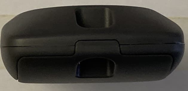
SU7318TRS8
Dec 12, 2022Part 15 Security / Remote Control Transmitter
Equipment Class
DSC - Part 15 Security/Remote Control Transmitter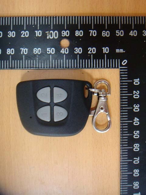
SU7IV318W4K
Oct 29, 2015Remote Controller
Equipment Class
DSC - Part 15 Security/Remote Control Transmitter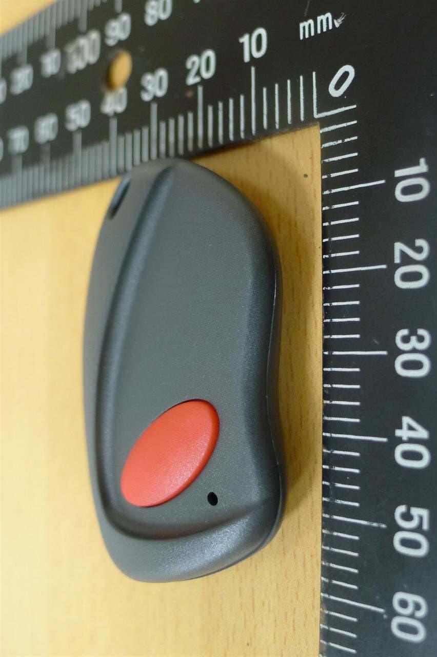
SU7INOX
Sep 30, 2015Remote Controller
Equipment Class
DSC - Part 15 Security/Remote Control Transmitter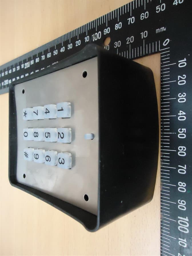
SU7DOL433RCP6SQ
Sep 12, 2015Remote Control
Equipment Class
DSC - Part 15 Security/Remote Control Transmitter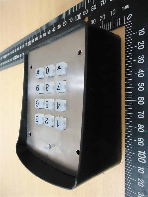
SU7DOL433RC6SQ
Sep 12, 2015Remote Control
Equipment Class
DSC - Part 15 Security/Remote Control Transmitter