SUN-0222200Telemetry Device
Simbex, LLC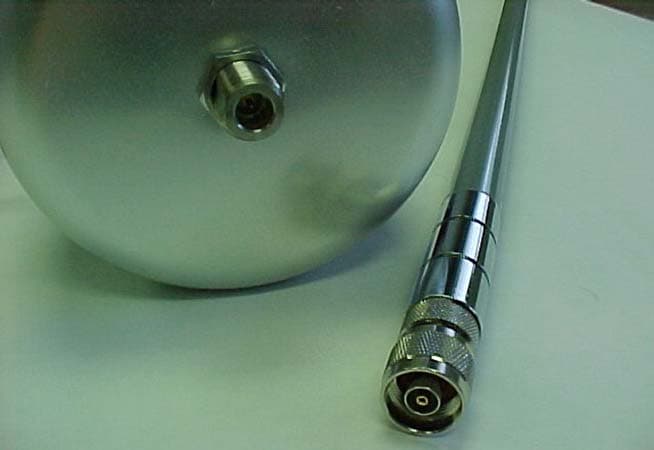
Click to zoom
Application Details
- Equipment Class
- DSS - Part 15 Spread Spectrum Transmitter
- Date of Grant
- Jun 06, 2005
- Application Purpose
- Original Equipment
- Date of Application
- Jun 06, 2005
- Equipment Note
- Telemetry Device
- Frequency Range
- 902.00000000 - 928.00000000
- Company
- Simbex, LLC
- Country
- United States
Documents & Files
Document Text
Text extracted from the exhibit documents filed with the FCC. Open a document above to read the original.
Users Manual
PRELIMINARY COPY P/N 02-81011 v 2.2 User Guide Please review this document thoroughly prior to using the HIT System™. Deleted: 0 PRELIMINARY COPY Page 2 of 19 P/N 02-81011 v 2.2 FCC Compliance Regulatory Statements These FCC statements apply to SIDELINE RECEIVER and MxENCODER: Compliance Statement ( Part 15.19 ) The SIDELINE RECEIVER and MxENCODER devices comply with Part 15 of the FCC Rules. Operation is subject to the following two conditions: 1. These devices may not cause harmful interference, and 2. These devices must accept any interference received, including interference that may cause undesired operation. Warning ( Part 15.21 ) Changes or modifications not expressly approved by the party responsible for compliance could void the user’s authority to operate the equipment. SIDELINE RECEIVER RF Exposure ( OET Bulletin 65 ) To comply with FCC’s RF exposure limits for general population / uncontrolled exposure, the antenna(s) used for this transmitter must be installed to provide a separation distance of at least 20 cm from all persons and must not be co-located or operating in conjunction with any other antenna or transmitter. MxENCODER This device and its antenna has shown compliance with FCC’s SAR limits for general population / uncontrolled exposure for a portable device. The maximum listed SAR level is 1.27 W/kg (head). The antenna used for this device must not be co-located or operating in conjunction with any other antenna or transmitter. Industry Canada Statement The term “IC” before the certification/registration number only signifies that the Industry Canada technical specifications were met. SIDELINE RECEIVER Section 5.5 of RSS-210 This device has been designed to operate with an antenna having a maximum gain of 5 dBi using an omni directional antenna. Antenna having a higher gain is strictly prohibited per regulations of Industry Canada. The required antenna impedance is 50 ohms. Section 5.11 of RSS-210 To reduce potential radio interference to other users, the antenna type and its gain should be so chosen that the equivalent isotropically radiated power (EIRP) is not more than that required for successful communication. MxENCODER Section 14 of RSS-210 The installer of this radio equipment must ensure that the antenna is located or pointed such that it does not emit RF field in excess of Health Canada limits for the general population. Consult Safety Code 6, obtainable from Health Canada’s website: www.hc-sc.gc.ca/rpb . Deleted: and 8 dBi if a directional patch antenna is used Deleted: 0 PRELIMINARY COPY Page 3 of 19 P/N 02-81011 v 2.2 INDEX INTRODUCTION 4 ABOUT SIMBEX 4 THE BASICS 5 INITIAL SETUP 6 FIELD CASE 6 BATTERY CHARGER CASE 8 MXENCODER INSTALLATION 9 PRE-GAME SETUP 10 HIT SYSTEM™ SETUP 10 SOFTWARE INITIALIZATION 10 MXENCODER BATTERY PACK INSTALLATION 11 SOFTWARE GUIDE 12 LAYOUT 12 SOFTWARE USE 15 DATA ANALYSIS 17 POST-GAME BREAKDOWN 18 MAINTENANCE 19 TROUBLESHOOTING 19 CONTACT INFORMATION 19 Copyrights - Copyright 2004 by Simbex LLC. All rights reserved. Patents - This product covered by US Patent 6,826,509, other patents pending. Deleted: 0 PRELIMINARY COPY Page 4 of 19 P/N 02-81011 v 2.2 INTRODUCTION Trainers, coaches and officials of contact sports have long sought to protect players from head injury. But, in hard-hitting sports like football, what can be done? The best equipment, coaching and enforcement of the rules cannot completely protect against mild brain trauma and concussion. Potential injury-producing impacts can go unnoticed and the resulting physiological damage may even be cumulative. Groundbreaking technology developed by Simbex and supported by the National Institutes of Health could change all that. The system is called the Head Impact Telemetry System™ (HIT System™) and is the first device to continuously monitor, analyze and record a player’s on-field head impact experience, and which is practical enough to be used in all game and practice situations. The HIT System not only monitors and records the impact history for all players simultaneously, but also can signal the sidelines staff to the occurrence of an impact that conforms to a Suspect Impact Profile™. The system monitors standard impact measures, such as maximum g’s, Head Impact Criteria (HIC), and Gadd Severity Index (GSI), or customized metrics based on any of the following components: • Impact location • Impact magnitude • Impact duration • Linear and angular acceleration components • And the exact times, of single or multiple impacts for improved player protection from serious injury. About Simbex – “Simply Better Exercise ” The Head Impact Telemetry System has been developed and patented by Simbex. Simbex has been researching, testing and creating products that benefit active people since its inception. Simbex is a research and product development company, specializing in biomechanical feedback systems, with research awards from the National Institutes of Health and the National Science Foundation. Our goal is to bring to market Deleted: 0 PRELIMINARY COPY Page 5 of 19 P/N 02-81011 v 2.2 the most innovative products and timely solutions for “active life improvement” in the areas of prosthetics, rehabilitation, and injury prevention. It is our sincere hope that Simbex, our research / development partners and this technology will combine to make contact sports safer for all players. For more information, please visit us on the web @ www.simbex.com . The Basics Please read this User’s Guide completely before set-up and use of the HIT System. If you need assistance with your first use of the system, please call Simbex Technical Support at the number listed in the CONTACT INFORMATION section. The HIT System™ is comprised of four main systems: the MXEncoders, the Sideline Receiver, the Alert Pager, and the Computer. The Sideline Receiver, Alert Pager, and Computer are all stored within a protective Field Case. The MX Encoders are installed inside Riddell VSR-4 and Revolution football he…
Text truncated - open the document above for the full version.
Cover Letter(s)
10 Water Street, Suite 410 Lebanon, NH 03766 T: 603-448-2367 F: 603-448-0380 F C C A U T H O R I Z A T I O N Date: 01/31/05 Time: 11:15 a.m To: FCC Authorization & Evaluation Division 7435 Oakland Mills Road Columbia, MD 21045-0429 From: Richard M. Greenwald Phone: 603-448-2367 President Fax: 603-448-0380 Applicant: Simbex LLC E-Mail: [email protected] ________________________________________________________________________ Dear Ladies and/or Gentlemen: I appoint Kenneth L. Boston, James Blaha and Teresa White at L.S. Compliance, Inc., to act as an agent in the preparation of applications under Part 15 of the rules and regulations of the Federal Communications Commission. I certify that the exhibitions properly describe the device being submitted under this application and will implement any changes described in the test report. The labels described will be affixed to each item. The following statement is required by the Federal Communications Commission: By checking Yes, the applicant certifies that, in the case of an individual applicant, he or she is not subject to a denial of federal benefits, that included FCC benefits, pursuant to section 5301 of the Anti-Drug Abuse Act of 1988, 21 U.S.C 853(a), or, in the case of a non-individual applicant (e.g. corporation, partnership, or other unincorporated association), no party to the application is subject to a denial of federal benefits, that includes FCC benefits, pursuant to that section. ___X___YES _______NO Dated this ___31 st _day of __January__, 2005 _____________________________________ By: Richard M. Greenwald, PhD Title: President Phone: 603-448-2367
Cover Letter(s)
PAWOD9 ...DATA SHEET... NLOS Series Vertically Polarized Omni Antenna 900 to 928 MHz Operation Features • 900MHz Omni Directional Antenna • Available in 5, 6, 8 and 11dBi gain models • 1degree electrical downtilt available on the 11dBi model • UV Stabilized Fiberglass / Stainless Steel Construction • 18” Pigtail with Type N Female Connector Standard ( 6dBi and 8dBi Models Only) • Available with RPTNC, RPN and N Connectors Applications • 900 MHz ISM Band Applications • Non Line of Sight Applications • WISP Base Station Equipment • Point to Multi-point Systems Description The NLOS Series Omnidirectional Antenna system offered by Pacific Wireless are constructed of UV stabilized fiberglass and Stainless Steel for long service life. Mounting is easy with a dual u-bolt mounting system. The antennas are vertically polarized. The 6dBi and 8dBi come standard with 18” pigtails terminated in an N female connector. The 5dBi and 11dBi comes standard with an integrated N Female connector. The omni’s are DC grounded for lightning protection. New in 2004 is the 11dBi omni with 1 deg electrical downtilt which gives improved close-in coverage. Specifications Parameter Min Typ Max Units Frequency Range 900 928 MHz Input Return Loss (S 11 ) -14 dB VSWR 1.5:1 Impedance 50 OHM Input Power 100 W Pole Diameter (OD) 1 (25) 2 (51) Inch (mm) Operating Temperature -45 +70 Deg C Rated Wind Velocity 125 (56) Mph (m/sec) *Note: Pacific Wireless does not supply the mounting pole 900 − 928 ΜΗΖ OD9-5 OD9-6 OD9-8 OD9-11 OD9-11D1 Gain 5dBi 6dBi 8dBi 11dBi 11dBi Vertical 3dB Beamwidth 36 Deg 16 deg 10 deg 7 deg 7 deg Electrical Downtilt 0 0 0 0 1 deg Weight 1.3 Lbs (.6 Kg) 5.4 Lbs (2.0 Kg) 6.7 Lbs (2.5 Kg) 9.4 Lbs (3.5 Kg) 9.4 Lbs (3.5 Kg) Length Dimension 24” (610 mm) 5.6’ (1.7 m) 8.5’ (2.6 m) 11’ (3.4 m) 11’ (3.4 m) Pacific Wireless 693 E Draper Heights Way Suite 210 Draper, UT 84020 TEL (801) 572-3024 FAX (801) 572-3025 www.pacwireless.com 6dBi Omni 5dBi Omni PAWOD9 Specifications Subject to Change Without Notice PAWOD9 Spec Rev 5 31-Mar-05 Page 2 Diameter = ~1.5”( 38 mm) Antenna Patterns at 910 MHz Notes: • All shipments F.O.B. Bluffdale, UT 84065 • All antennas carry a 2 Year Warranty System Ordering: OD9-5 5dBi Slimline NLOS Series 900MHz Omni Antenna with N Female Bulkhead Connector OD9-6 6dBi NLOS Series 900MHz Omni Antenna with 18” Pigtail/N Female Connector OD9-8 8dBi NLOS Series 900MHz Omni Antenna with 18” pigtail N Female Connector OD9-11 11dBi NLOS Series 900MHz Omni Antenna with Integrated N Female Connector OD9-11D1 11dBi 1deg elec downtilt NLOS Series 900MHz Omni Antenna with Integrated N Female Connector For further information contact: Pacific Wireless 693 E Draper Heights Way Suite 210 Draper, UT 84020 TEL (801) 572-3024 FAX (801) 572-3025 www.pacwireless.com OD9-6 E Plane OD9-8 E Plane OD9-11 E Plane OD9-5 E Plane OD9-5 OD9-6, OD9-8, OD9-11 OD9-11D1 E Plane
Cover Letter(s)
10 Water Street, Suite 410 Lebanon, NH 03766 T: 603-448-2367 F: 603-448-0380 F C C CONFIDENTIALITY Date: 01/31/05 Time: 11:15 a.m To: FCC Authorization & Evaluation Division 7435 Oakland Mills Road Columbia, MD 21045-0429 From: Richard M. Greenwald Phone: 603-448-2367 President Fax: 603-448-0380 Applicant: Simbex LLC E-Mail: [email protected] ________________________________________________________________________ Subject: Request for Non disclosure for FCC ID: SUN–0222200 To Whom It May Concern: Pursuant to 47 CFR Section 0.459, Simbex hereby requests non disclosure and confidential treatment of the following materials submitted in support of FCC certification application for FCC ID # SUN–0222200. a. Schematic Diagrams b. Operational Description c. Block Diagram Above materials contain trade secrets, proprietary and technical information which would customarily be guarded from competitors under 47 CRF section 0.457(d)(2). Disclosure or publication of any portion of this company confidential material to other parties could cause substantial competitive harm and provide unjustified benefits for competitors. Simbex understands that pursuant to 47 CFR section 0.457(d)(1)(ii) disclosure of the applicant and all accompanying documentation will not be made before the date of the grant. Sincerely yours, _____________________________________ By: Richard M. Greenwald, PhD Title: President Phone: 603-448-2367
Cover Letter(s)
Response to TCB Findings 1. The schematic diagram of the transmitter module is required. The supplied schematic shows the transmitter as a block without details of it. Detailed schematic supplied. 2. The manual on Pg 2 mentions an 8dBi patch antenna for the device. If that applies to FCC certification, then test data for this antenna is required. Otherwise this antenna must be removed from the manual entirely. Manual corrected
External Photos
Simbex, LLC Real-Time Head Acceleration Monitor Sideline Receiver 902 – 928 MHz FCC ID: SUN-0222200 Photo One – External Football Helmet with Sideline Transceiver / Antenna Simbex, LLC Real-Time Head Acceleration Monitor Sideline Receiver 902 – 928 MHz FCC ID: SUN-0222200 Photo Two – External Sideline Transceiver / Antenna Connection Simbex, LLC Real-Time Head Acceleration Monitor Sideline Receiver 902 – 928 MHz FCC ID: SUN-0222200 Photo Three – External Sideline Transceiver / Antenna Connection Close-Up Simbex, LLC Real-Time Head Acceleration Monitor Sideline Receiver 902 – 928 MHz FCC ID: SUN-0222200 Photo Four – External Sideline Transceiver / FCC Label Location Simbex, LLC Real-Time Head Acceleration Monitor Sideline Receiver 902 – 928 MHz FCC ID: SUN-0222200 Photo Five – External Sideline Transceiver / FCC Label Close-Up
ID Label/Location Info
Sideline Receiver Draft Label [________2.625”____________] This device complies with Part 15 of the FCC Rules. Operation is subject to the following two conditions: 1) this device may not cause harmful interference, and 2) this device must accept any interference received, including interference that may cause undesired operation. FCC ID: SUN-0222200 IC: 5602A-0222200 Notes: 1. Material: Weatherproof white polyester 2. Print: Text and Graphics-Black 3. Adhesive adheres to metal, plastic, glass, etc. 4. Manufacturer: Avery 1.000”
Internal Photos
Simbex, LLC Real-Time Head Acceleration Monitor Sideline Receiver 902 – 928 MHz FCC ID: SUN-0222200 Photo Three – Internal Sideline Transceiver / Close-Up of Internal Antenna Connection Simbex, LLC Real-Time Head Acceleration Monitor Sideline Receiver 902 – 928 MHz FCC ID: SUN-0222200 Photo Five – Internal Sideline Transceiver / Transceiver Module Flip Side Simbex, LLC Real-Time Head Acceleration Monitor Sideline Receiver 902 – 928 MHz FCC ID: SUN-0222200 Photo Six – Internal Sideline Transceiver / Transceiver Module RF Section Close-Up
Test Report
L.S. Compliance, Inc. W66 N220 Commerce Court Cedarburg, WI 53012 262-375-4400 Fax: 262-375-4248 COMPLIANCE TESTING OF: Sideline Receiver Prepared For: Simbex, LLC Attention: Mr. Jeffrey Chu 10 Water Street, Suite 410 Lebanon, NH 03766 Test Report Number: 304555-Tx Test Dates: March 7 TH through March 28 TH , 2005 All results of this report relate only to the items that were tested. This report is not to be reproduced, except in full, without written approval of L. S. Compliance, Inc. L.S. Compliance, Inc. Page 2 of 48 Test Report Number: 304555-Tx Prepared For: Simbex, LLC Table of Contents Section Description Page Index 2 1 L. S. Compliance in Review 3 2 A2LA Certificate of Accreditation 4 3 A2LA Scope of Accreditation 5 4 Validation Letter-U.S. Competent Body for EMC Directive 89/336/EEC 6 5 Signature Page 7 6 Product and General Information 8 7 Introduction 8 8 Product Description 9 9 Test Requirements 10 10 Summary of Test Report 10 11 Radiated Emissions Test 11-20 12 Band-Edge Measurements 21-22 13 Conducted Emissions onto AC Power Line 23-27 14 Occupied Bandwidth 28-29 15 RF Power Output 30-31 16 Spurious RF Emissions 32-33 17 Minimum Channel Separation 34-39 18 Channel Occupancy 40-41 19 Frequency and Power Stability requirements 42 20 Equal Channel Usage 43 21 Pseudorandom Hopping Pattern 43 22 Receiver Synchronization 44 23 Receiver Input Bandwidth 44 24 MPE Calculations 45 Appendix A Test Equipment List 46 B Antenna Specification Sheets 47 C Firmware and Setup Instructions 48 L.S. Compliance, Inc. Page 3 of 48 Test Report Number: 304555-Tx Prepared For: Simbex, LLC 1. L. S. Compliance In Review L.S. Compliance - Accreditations and Listing’s As an EMC Testing Laboratory, our Accreditation and Assessments are recognized through the following: A2LA – American Association for Laboratory Accreditation Accreditation based on ISO/IEC 17025 : 1999 with Electrical (EMC) Scope of Accreditation A2LA Certificate Number: 1255.01 Federal Communications Commission (FCC) – USA Listing of 3 Meter Semi-Anechoic Chamber based on Title 47 CFR – Part 2.948 FCC Registration Number: 90756 Listing of 3 and 10 meter OATS based on Title 47CFR – Part 2.948 FCC Registration Number: 90757 Industry Canada On file, 3 Meter Semi-Anechoic Chamber based on RSS-212 – Issue 1 File Number: IC 3088-A On file, 3 and 10 Meter OATS based on RSS-212 – Issue 1 File Number: IC 3088 U. S. Conformity Assessment Body (CAB) Validation Validated by the European Commission as a U. S. Competent Body operating under the U. S. /EU, Mutual Recognition Agreement (MRA) operating under the European Union Electromagnetic Compatibility –Council Directive 89/336/EEC, Article 10.2. Date of Validation: January 16, 2001 Validated by the European Commission as a U.S. Notified Body operating under the U.S./EU, Mutual Recognition Agreement (MRA) operating under the European Union Telecommunication Equipment – Council Directive 99/5/EC, Annex V. Date of Validation: November 20, 2002 Notified Body Identification Number: 1243 L.S. Compliance, Inc. Page 4 of 48 Test Report Number: 304555-Tx Prepared For: Simbex, LLC 2. A2LA Certificate of Accreditation L.S. Compliance, Inc. Page 5 of 48 Test Report Number: 304555-Tx Prepared For: Simbex, LLC 3. A2LA Scope of Accreditation L.S. Compliance, Inc. Page 6 of 48 Test Report Number: 304555-Tx Prepared For: Simbex, LLC 4. Validation Letter – U.S. Competent Body for EMC Directive 89/336/EEC L.S. Compliance, Inc. Page 7 of 48 Test Report Number: 304555-Tx Prepared For: Simbex, LLC 5. Signature Page Prepared By: April 29, 2005 Teresa A. White, Document Coordinator Date Tested By: April 29, 2005 Abtin Spantman, EMC Engineer Date Approved By: April 29, 2005 Kenneth L. Boston, EMC Lab Manager Date PE #31926 Licensed Professional Engineer Registered in the State of Wisconsin, United States L.S. Compliance, Inc. Page 8 of 48 Test Report Number: 304555-Tx Prepared For: Simbex, LLC 6. Product and General Information Manufacturer: Simbex, LLC Date(s) of Test: March 7 th through March 28 th , 2005 Test Engineer(s): Tom Smith √ Abtin Spantman Ken Boston Model #: Sideline Receiver Serial #: 15-000313 Voltage: 5.0 VDC Operation Mode: Normal, continuous transmit, and ‘Hopping’ mode 7. Introduction Between March 7 th and March 28 th , 2005, a series of Conducted and Radiated RF Emission tests were performed on one sample of the Simbex, LLC, Model Number Sideline Receiver (Note 1), , Serial Number 15-000313, here forth referred to as the “Equipment Under Test” or “EUT”. These tests were performed using the procedures outlined in ANSI C63.4-2003 for intentional radiators, and in accordance with the limits set forth in FCC Part 15.247 (Industry Canada RSS- 210) for a low power transmitter. These tests were performed by Abtin Spantman, EMC Engineer at L.S. Compliance, Incorporated. All Radiated and Conducted RF Emission tests were performed upon the EUT to measure the emissions in the frequency bands described in Title 47 CFR, FCC Part 15, including 15.35, 15.205, 15.247 and Industry Canada RSS-210 to determine whether these emissions are below the limits expressed within the standards. These tests were performed in accordance with the procedures described in the American National Standard for methods of measurement of Radio- Noise Emissions from Low-Voltage Electrical and Electronic Equipment in the Range of 9 kHz to 40 GHz (ANSI C63.4-2003). Another document used as a reference for the EMI Receiver specification was the Comite International Special Des Perturbations Radioelelectriques (CISPR) Number 16-1, 2003. All tests were performed at L.S. Compliance, Inc., in Cedarburg, Wisconsin, unless otherwise noted. Note 1: Although the unit has a model name and number listed as: “Sideline Receiver”, the unit actually contains a transceiver, of which the transmitter characteristics were tested and the results are presented in this report. L.S. Compliance, Inc. Page 9 of 48 Test Report Number: 304555-Tx Prepared For: Simbex, LLC …
Text truncated - open the document above for the full version.
Test Setup Photos
Close-up view of the EUT base and USB cable View of the EUT with the Monopole antenna. Front view of the EUT setup during radiated RF emissions tests Rear view of the EUT setup during radiated RF emissions tests, showing the host Laptop configuration Setup for the Conducted Emissions Test
Contact Information
Applicant
Amaris Ajamil(Director, Quality and Regulatory Affairs)
Test Firm
LS Research, LLCRyan Urness
Technical Specifications
| # | Rule Parts | Frequency Range | Power Output |
|---|---|---|---|
| 1 | 15C | 902 MHz - 928 MHz | 677.00 mW |
Other Applications from Simbex, LLC

SUN-R6252X
Jan 30, 2020InSite Player Unit
Equipment Class
DTS - Digital Transmission SystemSUN-0226000
Jun 27, 2005Telemetry Device
Equipment Class
DSS - Part 15 Spread Spectrum Transmitter