SUZ-PBP-IIInteractive Pen
Coretronic Corp.
Click to zoom
Application Details
- Equipment Class
- DXX - Part 15 Low Power Communication Device Transmitter
- Date of Grant
- Nov 04, 2010
- Application Purpose
- Original Equipment
- Date of Application
- Nov 04, 2010
- Equipment Note
- Interactive Pen
- Frequency Range
- 2402.25000000 - 2481.25000000
- Company
- Coretronic Corp.
- Country
- Taiwan
Documents & Files
Document Text
Text extracted from the exhibit documents filed with the FCC. Open a document above to read the original.
Users Manual
DLP® Products for Coretronic Interactive Pen -- PBP II Interactive Module--PBM User's G uide Product Specification Preliminary TI Confidential - NDA Restrictions Interactive Pen and Interactive Module user manual PointBlank Product Specification, Rev A Contents CONTENTS .................................................................................................................................... IV TABLES .......................................................................................................................................... V FIGURES......................................................................................................................................... V 1SCOPE ..................................................................................................................................... 1 2APPLICABLE DOCUMENTS .................................................................................................. 1 3OVERVIEW .............................................................................................................................. 2 4DETAILED DESCRIPTION...................................................................................................... 3 4.1P OINTBLANKHARDWARE..................................................................................................... 3 4.1.1PointBlank FPGA ....................................................................................................... 5 4.1.2PointBlank Radio Transceiver .(PBM)........................................................................ 5 4.1.3PointBlank Pointing Device .(PBP II).......................................................................... 5 4.2P OINTBLANKWIRELESS....................................................................................................... 6 4.3P OINTBLANKSOFTWARE..................................................................................................... 6 4.4O PERATING CONDITIONS..................................................................................................... 7 TI Confidential – NDA Restrictions IV PointBlank Product Specification, Rev A Tables TABLE 1 POINTBLANK OPERATING CONDITIONS ................................................................... 7 Figures FIGURE 1 POINTBLANK SYSTEM DIAGRAM ............................................................................. 2 FIGURE 2 POINTBLANK DDP2431 ELECTRONICS DIAGRAM .................................................. 3 FIGURE 3 POINTBLANK DDP2230 ELECTRONICS DIAGRAM .................................................. 4 TI Confidential – NDA Restrictions V Federal Communication Commission Interference Statement This equipment has been tested and found to comply with the limits for a Class B digital device, pursuant to Part 15 of the FCC Rules. These limits are designed to provide reasonable protection against harmful interference in a residential installation. This equipment generates, uses and can radiate radio frequency energy and, if not installed and used in accordance with the instructions, may cause harmful interference to radio communic ations. However, there is no guarantee that interference will not occur in a particular installation. If this equipment does cause harmful interference to radio or television reception, which can be determined by turning the equipment off and on, the user is encouraged to try to correct the interference by one of the following measures: - Reorient or relocate the receiving antenna. - Increase the separation between the equipment and receiver. - Connect the equipment into an outlet on a circuit different from that to which the receiver is connected. - Consult the dealer or an experienced ra dio/TV technician for help. FCC Caution: Any changes or modifications not expressly approved by the party responsible for compliance could void the user's authority to operate this equipment. This device complies with Part 15 of the FCC Rules. Operation is subject to the following two conditions: (1) This device may not cause harmful interference, and (2) this device must accept any interference received, including interference that may cause undesired operation. Industry Canada Statement This device complies with RSS-210 of the Industry Canada Rules. Operation is subject to the following two conditions: 1) this device may not cause interference and 2) this device must accept any interference, including interference that may cause undesired operation of the device IMPORTANT NOTE: IC Radiation Exposure Statement: This equipment complies with IC radiation exposure limits set forth for an uncontrolled environment. This equipment should be installed and operated with minimum distance 20cm between the radiator & your body. i NCC: FOR PBM ID FOR PBP PointBlank Product Specification, Rev A 1 Scope This document specifies the functional and performance parameters of the PointBlank enabled DLP® component set. PointBlank is supported on DDP2230 and DDP243x platforms by adding additional hardware and software components to the reference design. These additions are defined in this document. 2 Applicable Documents x DDP2230 Reference Design Documentation x DDP2431 Reference Design Documentation TI Confidential – NDA Restrictions 1 PointBlank Product Specification, Rev A 3 Overview A PointBlank enabled DLP® projector provides an interactive white board capability without requiring a white board or special screen. The PointBlank system is comprised of a laptop or desktop computer with USB mouse capability, a PointBlank enabled DLP® projector and a pointing device with a light sensor and RF transmitter. The PointBlank™ system is depicted in Figure 1. PointBlank-enabled DLP® projector PBMPBP II PC or laptop feedback via RF mouse via USB HID projected image with proprietary PointBlank encoding light sensor measurement image source (VGA, DVI) pointing oint DLP® projector PC or laptop feedback via RF mouse via USB HID projected …
Text truncated - open the document above for the full version.
External Photos
Page 1 CONSTRUCTION PHOTOS OF EUT Page 2
ID Label/Location Info
FCC LABEL LOCATION The label will be permanently affixed at a conspicuous location on the device. LABEL FCC ID: SUZ-PBP II FCC ID: SUZ-PBP-II
Internal Photos
Page 3 Page 4 Page 5 Page 6 Page 7 Page 8
Test Report
Report No.: RF991007E11 1 Report Format Version 3.0.1 FCC TEST REPORT REPORT NO.: RF991007E11 MODEL NO.: PBP II, AirWrite II FCC ID: SUZ-PBP-II RECEIVED: Oct. 07, 2010 TESTED: Mar. 01 to 17, 2010 and Oct. 12 to 15, 2010 ISSUED: Oct. 26, 2010 APPLICANT: Coretronic Corp. ADDRESS: No. 11, Li Hsing Rd, Science-Based Industrial Park, Hsinchu, Taiwan. ISSUED BY : Bureau Veritas Consumer Products Services (H.K.) Ltd., Taoyuan Branch Hsin Chu Laboratory LAB ADDRESS : No. 81-1, Lu Liao Keng, 9th Ling,Wu Lung Tsuen, Chiung Lin Hsiang, Hsin Chu Hsien 307, Taiwan TEST LOCATION (1): No. 81-1, Lu Liao Keng, 9th Ling,Wu Lung Tsuen, Chiung Lin Hsiang, Hsin Chu Hsien 307, Taiwan TEST LOCATION (2): No. 49, Ln. 206, Wende Rd., Shangshan Tsuen, Chiung Lin Hsiang, Hsin Chu Hsien 307, Taiwan This test report consists of 36 pages in total. It may be duplicated completely for legal use with the approval of the applicant. It should not be reproduced except in full, without the written approval of our laboratory. The client should not use it to claim product certification, approval, or endorsement by any government agencies. The test results in the report only apply to the tested sample. Report No.: RF991007E11 2 Report Format Version 3.0.1 Table of Contents 1 CERTIFICATION.....................................................................................................4 2 SUMMARY OF TEST RESULTS...........................................................................5 2.1 MEASUREMENT UNCERTAINTY........................................................................5 3 GENERAL INFORMATION....................................................................................6 3.1 GENERAL DESCRIPTION OF EUT.....................................................................6 3.2 DESCRIPTION OF TEST MODES.......................................................................8 3.2.1 TEST MODE APPLICABILITY AND TESTED CHANNEL DETAIL....................8 3.3 GENERAL DESCRIPTION OF APPLIED STANDARDS..................................10 3.4 DESCRIPTION OF SUPPORT UNITS...............................................................11 3.5 CONFIGURATION OF SYSTEM UNDER TEST...............................................12 4 TEST PROCEDURES AND RESULTS..............................................................15 4.1 CONDUCTED EMISSION MEASUREMENT.....................................................15 4.1.1 LIMITS OF CONDUCTED EMISSION MEASUREMENT.................................15 4.1.2 TEST INSTRUMENTS.........................................................................................15 4.1.3 TEST PROCEDURES..........................................................................................16 4.1.4 TEST SETUP........................................................................................................16 4.1.5 EUT OPERATING CONDITIONS........................................................................17 4.1.6 TEST RESULTS....................................................................................................18 4.2 RADIATED EMISSION MEASUREMENT..........................................................20 4.2.1 LIMITS OF RADIATED EMISSION MEASUREMENT......................................20 4.2.2 TEST INSTRUMENTS.........................................................................................21 4.2.3 TEST PROCEDURES..........................................................................................22 4.2.4 DEVIATION FROM TEST STANDARD..............................................................22 4.2.5 TEST SETUP........................................................................................................23 4.2.6 EUT OPERATING CONDITIONS........................................................................23 4.2.7 TEST RESULTS....................................................................................................24 4.3 CONDUCTED - OUT BAND MEASUREMENT.................................................32 4.3.1 LIMITS OF CONDUCTED - OUT BAND MEASUREMENT.............................32 4.3.2 TEST INSTRUMENTS.........................................................................................32 4.3.3 TEST PROCEDURE.............................................................................................32 4.3.4 DEVIATION FROM TEST STANDARD..............................................................32 4.3.5 EUT OPERATING CONDITION..........................................................................32 4.3.6 TEST RESULTS....................................................................................................33 5 INFORMATION ON THE TESTING LABORATORIES.....................................35 Report No.: RF991007E11 3 Report Format Version 3.0.1 6 APPENDIX A - MODIFICATIONS RECORDERS FOR ENGINEERING CHANGES TO THE EUT BY THE LAB..............................................................36 Report No.: RF991007E11 4 Report Format Version 3.0.1 1 CERTIFICATION PRODUCT : Interactive Pen BRAND NAME : Coretronic, Dell MODEL NO. : PBP II, AirWrite II TESTED : Mar. 01 to 17, 2010 (only for Conducted - out band measurement) and Oct. 12 to 15, 2010 (for other test items) TEST SAMPLE : ENGINEERING SAMPLE APPLICANT : Coretronic Corp. STANDARDS : FCC Part 15, Subpart C (Section 15.249) ANSI C63.4-2003 The above equipment (Model: PBP II) has been tested by Bureau Veritas Consumer Products Services (H.K.) Ltd., Taoyuan Branch, and found compliance with the requirement of the above standards. The test record, data evaluation & Equipment Under Test (EUT) configurations represented herein are true and accurate accounts of the measurements of the sample’s EMC characteristics under the conditions specified in this report. PREPARED BY : , DATE: Oct. 26, 2010 ( Carol Liao, Specialist ) TECHNICAL ACCEPTANCE : , DATE: Oct. 26, 2010 ( Hank Chung, Deputy Manager ) APPROVED BY : , DATE: Oct. 26, 2010 (May Chen, Deputy Manager ) Report No.: RF991007E11 5 Report…
Text truncated - open the document above for the full version.
Test Setup Photos
1 PHOTOGRAPHS OF THE TEST CONFIGURATION CONDUCTED EMISSION TEST 2 RADIATED EMISSION TEST (charger mode) 3 RADIATED EMISSION TEST (Battery mode)
Contact Information
Applicant
Roger Ren
Technical Contact
Bureau Veritas CPS (H.K.) Ltd. Taoyuan BranchHank Chung
[email protected]886-3-593-5343
81-1, Lu Laio Keng, 9th Ling, Wu Lung Tsuen, Chiun · Hsinchu Hsien · Taiwan
Non-Technical Contact
Bureau Veritas CPS (H.K.) Ltd. Taoyuan BranchNatacha Chen
[email protected]886-3-3183232
Test Firm
Bureau Veritas CPS (H.K.) Ltd. Taoyuan BranchRichard Chen
Technical Specifications
| # | Rule Parts | Frequency Range | Power Output |
|---|---|---|---|
| 1 | 15C | 2.40 GHz - 2.48 GHz | - |
Other Applications from Coretronic Corp.

SUZ-WN6500RHN
Jan 20, 2013802.11n, Dual Band, 2T2R Wireless LAN PCI Express Half Mini Module
Equipment Class
DTS - Digital Transmission System
SUZ-WN6500RH
Nov 27, 2012802.11n, Dual Band, 2T2R Wireless LAN PCI Express Half Mini Module
Equipment Class
NII - Unlicensed National Information Infrastructure TX
SUZ-PBP2
May 29, 2012Interactive Pen
Equipment Class
DXX - Part 15 Low Power Communication Device Transmitter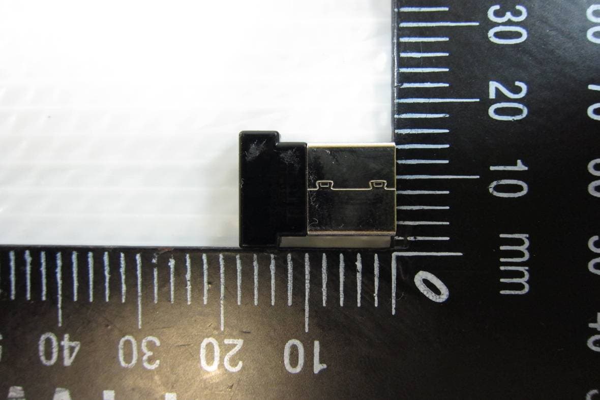
SUZ-PB2701
Apr 05, 2012Dell Interactive Wireless Dongle
Equipment Class
DXX - Part 15 Low Power Communication Device Transmitter
SUZ-WU5205C
Nov 04, 2010802.11b/g/n Mini Wireless LAN USB2.0 Adapter
Equipment Class
DTS - Digital Transmission System