SVM-PANSAT2700ADigital Satellite Receiver
Global Technologies Inc.
Click to zoom
Application Details
- Equipment Class
- HID - Part 15 TV Interface Device
- Date of Grant
- Mar 30, 2005
- Application Purpose
- Original Equipment
- Date of Application
- Mar 30, 2005
- Equipment Note
- Digital Satellite Receiver
- Frequency Range
- 67.25000000 - 71.75000000
- Company
- Global Technologies Inc.
- Country
- South Korea
Documents & Files
Document Text
Text extracted from the exhibit documents filed with the FCC. Open a document above to read the original.
Users Manual
FCC RFINTERFERENCE STATEMENTNOTE :This equipment has been tested and found to comply with the limits for a Class B digital device, pursuant to Part 15 of the FCC Rules. These limits are designed to provide reasonable protection against harmful interference in a residential installation.This equipment generates, uses and can radiate radio frequency energy and, if not installed and used in accordance with the instructions, may cause harmful interference to radio communications. However, there is no guarantee that interference will not occur in a particular installation.If this equipment does cause harmful interference to radio or television reception which can be determined by turning the equipment off and on, the user is encouraged to try to correct the interference by one or more of the following measures.- Reorient or relocate the receiving antenna. - Increase the separation between the equipment and receiver. - Connect the equipment into an outlet on a circuit different from that to which the receiver is connected.- Consult the dealer or an experienced radio, TV technical for help. - Only shielded interface cable should be used. Finally, any changes or modifications to the equipment by the user not expressly approved by the grantee or manufacturer could void the users authority to operate such equipment.
Block Diagram
A/V SWITCH A/V SWITCH SMPS LNB DRIVING PARTS AUDIO DAC AUDIO DAC T U N E R . PANSAT 2700A’S BLOCK DIAGRAM VIDEO FILTER VIDEO FILTER CINCH (VIDEO& AUDIO OUTPUT) RS-232 PORT FRONT PARTS UHF& SKEW SKEW DRIVING PARTS . PANSAT’S BLOCK DIAGRAM 5518 (DEMUX & MPEG DECODER) FLASH(16Mbit) EEPROM(32K)VCXO(27MHz) SDRAM(64Mbit) PROTECTION PARTS 121Mhz ... . PANSAT 2700A’S BLOCK DIAGRAM 5518 (DEMUX & MPEG DECODER) A/V SWITCH A/V SWITCH AUDIO DAC AUDIO DAC VIDEO FILTER VIDEO FILTER CINCH (VIDEO& AUDIO OUTPUT& 0/12V CONTROL) S-VIDEO UHF & DISEQ MOTOR
Cover Letter(s)
1 Subject:FW: Global Technologies Inc., FCC ID: SVM-PANSAT2700A, Assessment NO.: AN05T4660, Notice#1 From: sgkim Sent: Wednesday, March 30, 2005 9:39 PM To: Helen Zhao Subject: RE: Global Technologies Inc., FCC ID: SVM-PANSAT2700A, Assessment NO.: AN05T4660, Notice#1 Dear Helen, According to your comments, modified test report and ID label sample were uploaded to your web application. Please check and review the documents. Best regards, S.G.Kim / Asst.Manager -----Original Message----- From: Compliance Certification Services Sent: Wednesday, March 23, 2005 1:30 PM Subject: Global Technologies Inc., FCC ID: SVM-PANSAT2700A, Assessment NO.: AN05T4660, Notice#1 Quetsion #1: There are no calibration dates on the test report (page 13, 17, 20), instead it only stated that "The test equipment used is calibrated in regular for every year", which does not comply with ANSI C63.4 report format, please add calibration date for each equipment on the report. Question #2: The plots of "Transfer Switch Isolation Measurement" on the test report show the levels are all very close to the limit (9.53 dBuV), not around 5.3-5.9 dBuV as the indicated in the table. Please explain. Question #3: The Block Diagram shows the highest frequency used by the device is 121 MHz, the test report does not show that radiated emission from 1GHz to 2GHz has been investigated. Please explain. Question #4: The FCC ID label format shows there is a space between "SVM-PANSAT" and "2700A". Please revise the FCC ID label format to remove the space. Best Regards, Helen Zhao The items indicated above must be submitted before processing can continue on the above referenced application. Failure to provide the requested information within 30 days of the original e-mail date may result in application dismissal and forfeiture of the filing fee. Also, please note that partial responses increase processing time and should not be submitted. Any questions about the content of this correspondence should be directed to the e-mail address listed below the name of the sender.
External Photos
IST Co., Ltd. EMC LABORATORY External Photos.Ref.No : 05-IST-0143 1 of 2 The DUT photos Front View Rear View IST Co., Ltd. EMC LABORATORY External Photos.Ref.No : 05-IST-0143 2 of 2 The DUT photos Side View Side View
ID Label/Location Info
IST Co., Ltd. EMC LABORATORY Label Location.Ref.No : 05-IST-0143 1 of 1 Label Sample Label Location
Internal Photos
IST Co., Ltd. EMC LABORATORY Internal Photos. Ref.No: 05-IST-0143 1 of 9 The DUT photos Inner Top View Inner Top View IST Co., Ltd. EMC LABORATORY Internal Photos. Ref.No: 05-IST-0143 2 of 9 The DUT photos Main Board PCB Parts View Main Board PCB Copper View IST Co., Ltd. EMC LABORATORY Internal Photos. Ref.No: 05-IST-0143 3 of 9 The DUT photos Power Board PCB Parts View Power Board PCB Copper View IST Co., Ltd. EMC LABORATORY Internal Photos. Ref.No: 05-IST-0143 4 of 9 The DUT photos S-VHS Board PCB Parts View S-VHS Board PCB Copper View IST Co., Ltd. EMC LABORATORY Internal Photos. Ref.No: 05-IST-0143 5 of 9 The DUT photos Top Cover Inner Bottom IST Co., Ltd. EMC LABORATORY Internal Photos. Ref.No: 05-IST-0143 6 of 9 Tuner photos(F7VZ0614) Front View Rear View IST Co., Ltd. EMC LABORATORY Internal Photos. Ref.No: 05-IST-0143 7 of 9 Tuner photos(F7VZ0614) Inner Front View Inner Rear View IST Co., Ltd. EMC LABORATORY Internal Photos. Ref.No: 05-IST-0143 8 of 9 Modulator photos(RMVP13450WL) Front View Rear View IST Co., Ltd. EMC LABORATORY Internal Photos. Ref.No: 05-IST-0143 9 of 9 Modulator photos(RMVP13450WL) Inner Front View Inner Rear View
Test Report
IST Co., Ltd. EMC LABORATORY TEST REPORT NO. : 05-IST-0143 1 of 23 Certification of Compliance CFR 47 Part 15 Subpart B Test Report File No. 05-IST-0143 Date of Issue March 31,2005 Model(s) Pansat 2700A Kind of Product Digital Satellite Receiver Applicant Global Technologies Inc. 503 KICOX Venture Center B/D 188-5 Kuro-Dong, Kuro-Ku, Seoul, 152-848 Korea. Manufacturer Global Technologies Inc. 604 Sampoong Plaza Industrial Factory 474 Dangjung-Dong, Kunpo-City, Kyunggi-Do, 435-833 Korea. Test Result Positive Negative Reviewed By Approved By S.J.Cho / EMC Group Manager J.H.LEE / Chief - Investigations requested : Measurement to the relevant clauses of F.C.C rules and regulations Part 15 Subpart B – Unintentional Radiatiors - The test report with appendix consists of 23 pages. - The test result only responds to the tested sample. - It is not allowed to copy this report even partly without the allowance of IST EMC Laboratory. - This equipment as for has been shown to be capable of continued compliance with the applicable technical standards as indicated in the measurement report and was tested in accordance with the measurement procedures specified in ANSI C63.4 2003. IST Co., Ltd. EMC LABORATORY TEST REPORT NO. : 05-IST-0143 2 of 23 TABLE OF CONTENTS Table of contents 2 Information of test laboratory, Environmental condition, Power used 3 Descriptions of test 4-6 Conducted Emission 4 Radiated Emission 5 Output Signal level measurements 6 Output Terminal Conducted Spurious Emission 6 Transfer Switch Isolation Measurement 6 Summary 7 Test Conditions and Data - Emission Conducted Emission 0.15MHz - 30MHz Test equipment / Data and Plots 8-10 Radiated Emission 30MHz - 2GHz Test equipment / Data and Plots 11-13 Output Signal level measurements Test equipment / Data and Plots 14-17 Output Terminal Conducted Spurious Emission 30MHz - 1GHz Test equipment / Data and Plots 18-20 Transfer Switch Isolation Measurement 30MHz - 1GHz Test equipment / Data and Plots 21-23 Information OF TUNERS Manufacture Manufacture Name Sharp F7VZ0614 Tuner Samsung RMVP13450WL RF Modulator IST Co., Ltd. EMC LABORATORY TEST REPORT NO. : 05-IST-0143 3 of 23 INFORMATIONS OF TEST LABORATORY EMC LABORATORY of IST Co., Ltd.(FCC Filing Lab) San 21-8, Goan-Ri, Baekam-Myun, Yongin-City Kyonggi-Do, 449-860, Korea TEL : +82 31 333 4093 FAX : +82 31 333 4094 ENVIRONMENTAL CONDITIONS Temperature 14 Humidity 48 % Atmospheric pressure 1002 mbar POWER SUPPLY SYSTEM USED Power supply system 120Vac , 60Hz PRODUCT INFORMATIONS Power supply system 100-120Vac , 50/60Hz Power consumption Max. 25W Tuner/LNB IF input frequency : 950-2150 MHz IF Loop Throughout : 950-2150 MHz IF frequency : Zero IF LNB Power : 13/18V DC Current : 500mA(MAX) Demodulation : QPSK A/V Decoding Audio Decoding: MPEG Layer I II RF Modulator frequency : 470-860 MHz - EMC suppression device is not used during the test. - Please refer to user’s manual. IST Co., Ltd. EMC LABORATORY TEST REPORT NO. : 05-IST-0143 4 of 23 DESCRIPTIONS OF TEST Conducted Emissions: The measurement were performed over the frequency range of 0.45MHz to 30MHz using a 50/50uH LISN as the input transducer to a Spectrum Analyzer or a Field Intensity Meter. The measurements were made with the detector set for "Peak" amplitude within an bandwidth of 10KHz or for "quasi-peak" within a bandwidth of 9KHz. - Procedure of Test The line-conducted facility is located inside a shielded room No.1. A 1m X 1.5m wooden table 80cm height is placed 40cm away from the vertical wall and 1.5m away from the other wall of the shielded room. The R/S ESH3-Z5 and EMCO 3825/2 LISN are bonded to bottom of the shielded room. The EUT is located on the wooden table with distance more than 80cm from the LISN and powered from the EMCO LISN .The peripheral equipment is powered from the other LISN. Power to the LISNs are filtered by a noise cut power line filters. All electrical cables are shielded by braided tinned steel tubing with inner ? 1.2cm. If the EUT is a DC-powered device, power will be derived from the source power supply it normally will be powered from and this supply lines will be connected to the EMCO LISN. All interconnecting cables more than 1m were shortened by non-inductive bundling to a 1m length. Sufficient time for the EUT, support equipment, and test equipment was allowed in order for them to warm up to their normal operating conditions. The RF output of the LISN was connected to the R/S receiver to determine the frequency producing the maximum emission from the EUT. The frequency producing the maximum level was reexamined using Quasi-Peak mode by manual measurement, after scanned by automatic Peak mode for frequency range from 0.45 to 30MHz. The bandwidth of the receiver was set to 10kHz. The EUT, peripheral equipment, and interconnecting cables were arranged and manipulated to maximize each EME emission. 215 >150>40 80 Receiver EUT LISN 80 ? 80 80 40 ? 80 Measuring apparatus Mains Filter Mains Rear side Equipment under test Coaxial cable Artificial mains network Screened room Non-metallic support 80 < Side View > < Concept Drawing > IST Co., Ltd. EMC LABORATORY TEST REPORT NO. : 05-IST-0143 5 of 23 DESCRIPTION OF TEST Radiated Emissions: The measurement was performed over the frequency range of 30MHz to 1GHz using antenna as the input transducer to a Spectrum analyzer or a Field Intensity Meter. The measurement was made with the detector set for "quasi-peak" within a bandwidth of 120KHz. - Procedure of Test Preliminary measurements were made at 3 meter using bi-conical and log-periodic antennas, and spectrum analyzer to determine the frequency producing the max. emission in anechoic chamber. Appropriate precaution was taken to ensure that all emission from the EUT were maximized and investigated. The system configuration, mode of operation, turn table azimuth and height with respect to the antenna were noted for each frequency found. The spectrum was scanned from 40MHz to 300MHz using S/B bi- conical antenna …
Text truncated - open the document above for the full version.
Test Setup Photos
IST Co., Ltd. EMC LABORATORY Test Setup Photos. Ref. No: 05-IST-0143 1 of 2 Test Setup Photos – Radiated Emissions Front View Rear View IST Co., Ltd. EMC LABORATORY Test Setup Photos. Ref. No: 05-IST-0143 2 of 2 Test Setup Photos – Conducted Emissions Front View Rear View
Contact Information
Applicant
Sung Jin Kang(Manager)
Test Firm
IST Co., LtdBong Kyoon Bae
Technical Specifications
| # | Rule Parts | Frequency Range | Power Output |
|---|---|---|---|
| 2 | 15B | 67.25 MHz - 71.75 MHz | - |
Other Applications from Global Technologies Inc.

SVM-PANSAT250SM
Jan 29, 2007Digital Set-top Box
Equipment Class
HID - Part 15 TV Interface Device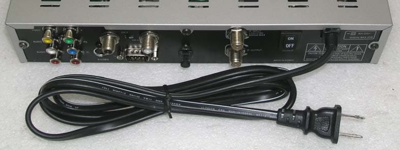
SVM-ARIZA800S
Feb 02, 2006Digital Satellite Receiver
Equipment Class
HID - Part 15 TV Interface Device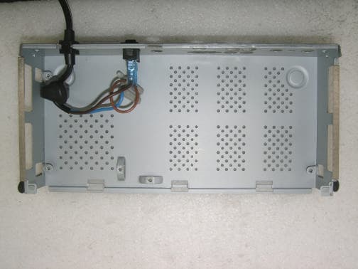
SVM-ARIZA750CX
Nov 24, 2005Digital Satellite Receiver
Equipment Class
HID - Part 15 TV Interface Device