SWTRF-101-5Wireless Thermometer Model: RF-101-5
Calibeur Measurements (Hong Kong) Co., Limited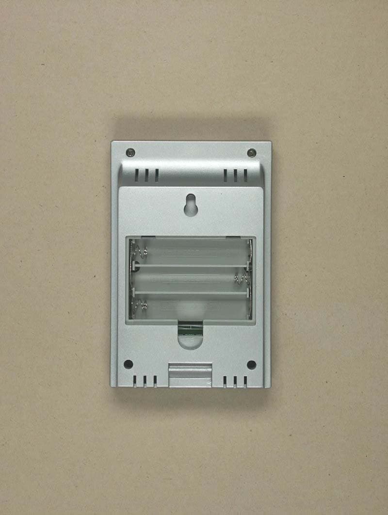
Click to zoom
Application Details
- Equipment Class
- DXX - Part 15 Low Power Communication Device Transmitter
- Date of Grant
- Apr 11, 2005
- Application Purpose
- Original Equipment
- Date of Application
- Apr 11, 2005
- Equipment Note
- Wireless Thermometer Model: RF-101-5
- Frequency Range
- 434.00000000 - 434.00000000
- Country
- China
Documents & Files
Document Text
Text extracted from the exhibit documents filed with the FCC. Open a document above to read the original.
Users Manual
RF-101 Wireless 433 MHz Temperature Station Instruction Manual Statements This device complies with Part 15 of the FCC Rules. Operation is subject to the following two conditions: (1) this device may not cause harmful interference, and (2) This device must accept any interference received, including interference that may cause undesired operation. Warning: Changes or modifications to this unit not expressly approved by the party responsible for compliance could void the user’s authority to operate the equipment. Note: This equipment has been tested and found to comply with the limits for a Class B digital device, pursuant to Part 15 of the FCC Rules. These limits are designed to provide reasonable protection against harmful interference in a residential installation. This equipment generates, uses and can radiate radio frequency energy and, if not installed and used in accordance with the instructions, may cause harmful interference to radio communications. However, there is no guarantee that interference will not occur in a particular installation. If this equipment does cause harmful interference to radio or television reception, which can be determined by turning the equipment off and on, the user is encouraged to try to correct the interference by one or more of the following measures: - Reorient or relocate the receiving antenna. - Increase the separation between the equipment and receiver. - Connect the equipment into an outlet on a circuit different from that to which the receiver is connected. - Consult the dealer or an experienced radio/TV technician for help. TABLE OF CONTENTS Topic Page Inventory of Contents 1 Quick Setup 2 Detailed Setup Guide Battery Installation 3-4 Setting the Time 5 Selecting Units of Measurement 6 Features Minimum and Maximum Temperatures 6-7 Resetting Minimum and Maximum Temperatures 7 Mounting 7-8 Troubleshooting 9-10 Maintenance and Care 11 Specifications 12-13 INVENTORY OF CONTENTS 1.The Indoor Temperature Station (Figure 1) 2.The Remote Control Sensor and mounting bracket. (Figure 2) 3.3 screws. 4.One strip of double sided adhesive tape. 5.Instruction Manual. Figure 1 Figure 2 ADDITIONAL EQUIPMENT (not included) 1. 1 Screwdriver. 2. 3 Fresh AAA 1.5V batteries. 3. 2 Fresh AAA 1.5V batteries. QUICK SETUP 1.Insert three AAA batteries into the Indoor Temperature Station. 2.Insert two AAA batteries into the Remote Control Sender. 3.Wait 2-3 minutes, or until the outdoor temperature is displayed in the OUTDOOR LCD of the Temperature Station. 4.Set the Time 5.Mount units. (See complete instructions for details). Note: The Remote Control Sender transmits a signal every 3 minutes. After the batteries have been installed, the Indoor Temperature Station searches for these signals for a duration of 3 minutes. If there is no temperature reading in the “OUTDOOR” of the LCD after 3 minutes, make sure the units are within range of each other, or repeat battery installation process. DETAILED SETUP GUIDE I. BATTERY INSTALLATION A. TEMPERATURE STATION 1.Remove the battery cover on the backside. To do this, push up and pull out. 2.Observing the correct polarity, install 3 AAA batteries. 3.Replace battery cover. 4.Wait 2-3 minutes or until both indoor and outdoor temperatures are shown on the Indoor Temperature Station. 5.The Temperature Station should now show: “0:00” in the TIME LCD, and temperatures in the INDOOR and OUTDOOR LCD’s. B. REMOTE CONTROL SENDER Battery compartment 1.Remove the mounting bracket. 2.Remove battery cover 3.Observing the correct polarity, install 2 AAA batteries—make sure they do not spring free, or start-up problems may occur. Replace cover. Battery cover Battery cover II. TIME A. SETTING THE TIME 1. Press and hold the MENU/SET button for 3 seconds. “24h” will appear in the TIME LCD. 2. Use the MAX/MIN button to select either 12h time (am/pm) or 24h time 3. Press the MENU/SET button 2 times, the hour will flash in the upper left corner. 4. Press the MAX/MIN button to set the hours, press the MENU/SET button, and press the MAX/MIN button to set the minutes. 5. Press the MENU/SET button to activate the clock. Note: When in 12h mode, there is only a “PM” display, which appears under “TIME.” If there is no display here it is AM. Make sure you set the time accordingly. III. UNITS OF TEMPERATURE MEASURE A. SELECTING UNITS OF MEASUREMENT 1. Press and hold the MENU/SET button for 1 second. 2. Press the MENU/SET button again. “°F” will appear in the TIME LCD. 3. Press the MAX/MIN button to shift between °F and °C. 4. Press the MENU/SET button twice to activate settings. IV. FEATURES A. MINIMUM AND MAXIMUM TEMPERATURES 1. Press the MAX/MIN button. “MAX” appears in the temperature LCD’s and the recorded maximum temperatures are displayed. 2. Press the MAX/MIN button to toggle to the minimum temperatures. B. RESETTING THE MINIMUM AND MAXIMUM TEMPERATURES 1. To reset both the minimum and maximum temperatures—press and hold the RESET/+ button for 3 seconds. V. MOUNTING A. Note: To achieve a true temperature reading, avoid mounting in direct sunlight. We recommend that you mount the Sender on an outside North-facing wall. The sending range is 80ft; obstacles such as walls, concrete, and large metal objects will reduce the range. Place both units in their desired location before permanently mounting. B. REMOTE CONTROL SENDER 1. Remove the mounting bracket from the Remote Control Sender and mount with either screws or adhesive tape. C.THE TEMPERATURE STATION 1.The Indoor Temperature Station comes with the table stand already mounted. If you wish to use the table-stand, all that is required is to place the Indoor Temperature Station in an appropriate location. 2.To wall mount, remove the table stand. To do this, pull down on the stand from the rear and rotate forward. a) Fix a screw (not included) into the desired wall, and place the Temperature Station onto the screw using the hanging hole on the backside. Gently pull the Station down to lock the screw into p…
Text truncated - open the document above for the full version.
External Photos
ELECTRONIC TECHNOLOGY SYSTEMS DR.GENZ GMBH ETS Dr. Genz GmbH, Germany Registration number: G4M20501-0148-C-1 Page 1 of 14 Appendix A. Pictures ELECTRONIC TECHNOLOGY SYSTEMS DR.GENZ GMBH ETS Dr. Genz GmbH, Germany Registration number: G4M20501-0148-C-1 Page 2 of 14 ELECTRONIC TECHNOLOGY SYSTEMS DR.GENZ GMBH ETS Dr. Genz GmbH, Germany Registration number: G4M20501-0148-C-1 Page 3 of 14 ELECTRONIC TECHNOLOGY SYSTEMS DR.GENZ GMBH ETS Dr. Genz GmbH, Germany Registration number: G4M20501-0148-C-1 Page 4 of 14 ELECTRONIC TECHNOLOGY SYSTEMS DR.GENZ GMBH ETS Dr. Genz GmbH, Germany Registration number: G4M20501-0148-C-1 Page 7 of 14 ELECTRONIC TECHNOLOGY SYSTEMS DR.GENZ GMBH ETS Dr. Genz GmbH, Germany Registration number: G4M20501-0148-C-1 Page 8 of 14 ELECTRONIC TECHNOLOGY SYSTEMS DR.GENZ GMBH ETS Dr. Genz GmbH, Germany Registration number: G4M20501-0148-C-1 Page 9 of 14
Internal Photos
ELECTRONIC TECHNOLOGY SYSTEMS DR.GENZ GMBH ETS Dr. Genz GmbH, Germany Registration number: G4M20501-0148-C-1 Page 5 of 14 ELECTRONIC TECHNOLOGY SYSTEMS DR.GENZ GMBH ETS Dr. Genz GmbH, Germany Registration number: G4M20501-0148-C-1 Page 6 of 14 ELECTRONIC TECHNOLOGY SYSTEMS DR.GENZ GMBH ETS Dr. Genz GmbH, Germany Registration number: G4M20501-0148-C-1 Page 10 of 14 ELECTRONIC TECHNOLOGY SYSTEMS DR.GENZ GMBH ETS Dr. Genz GmbH, Germany Registration number: G4M20501-0148-C-1 Page 11 of 14
Test Report
ELECTRONIC TECHNOLOGY SYSTEMS DR. GENZ GMBH TEST - REPORT FCC RULES PART 15 / SUBPART B and C Test report no.: G4M20501-0148-C-1 FCC ID: SWTRF-101-5 ELECTRONIC TECHNOLOGY SYSTEMS STORKOWER STRASSE 38C, D-15526 REICHENWALDE B. BERLIN DR. GENZ GMBH PHONE +49-33631-888 00 FAX +49-33631-888 66 ETS Dr. Genz GmbH, Germany Registration number: G4M20501-0148-C-1 Page 2 of 30 ELECTRONIC TECHNOLOGY SYSTEMS DR.GENZ GMBH TABLE OF CONTENTS 1 General information 1.1 Notes 1.2 Testing laboratory 1.3 Details of approval holder 1.4 Application details 1.5 Test item 1.6 Test standards 2 Technical test 2.1 Summary of test results 2.2 Test environment 2.3 Test equipment utilized 2.4 Test Procedure 3 Test Results 3.1 Output power 3.2 Out of band radiated emission 3.3 Transmitter radiated emissions in restricted bands 3.4 Spurious emissions radiated, transmitter 3.5 20 dB bandwidth 3.6 Spurious emissions radiated, receiver 3.7 Automatical deactivation 3.8 Conduted measurement at (AC) power line ETS Dr. Genz GmbH, Germany Registration number: G4M20501-0148-C-1 Page 3 of 30 ELECTRONIC TECHNOLOGY SYSTEMS DR.GENZ GMBH 1 General Information 1.1 Notes The purpose of conformity testing is to increase the probability of adherence to the essential requirements or conformity specifications, as appropriate. The complexity of the technical specifications, however, means that full and thorough testing is impractical for both technical and economic reasons. Futhermore, there is no guarantee that a test sample which has Passed all the relevant tests conforms to a specification. Neither is there any guarantee that such a test sample will interwork with other genuinely open systems. The existence of the tests nevertheless provides the confidence that the test sample posseses the qualities as maintained and that is performance generally conforms to representative cases of communications equipment. The test results of this test report relate exclusively to the item tested as specified in 1.5. The test report may only be reproduced or published in full. Reproduction or publication of extractes from the report requires the prior written approval of the ELECTRONIC TECHNOLOGY SYSTEMS DR. GENZ GMBH. Tester: 15.03.2005 N. Kaspar Date ETS-Lab. Name Signature Technical responsibility for area of testing: 15.03.2005 Dr. Genz Date ETS Name Signature ETS Dr. Genz GmbH, Germany Registration number: G4M20501-0148-C-1 Page 4 of 30 ELECTRONIC TECHNOLOGY SYSTEMS DR.GENZ GMBH 1.2 Testing laboratory 1.2.1 Location ELECTRONIC TECHNOLOGY SYSTEM DR. GENZ GMBH (ETS) Storkower Straße 38c D-15526 Reichenwalde b. Berlin Germany Telefon : +49 33631 888 00 Telefax : +49 33631 888 66 1.2.2 Details of accreditation status A CCREDITED TESTING LABORATORY DAR-REGISTRATION NUMBER: TTI-P-G 126/96-30 ACCREDITED COMPETENT BODY DAR-REGISTRATION NUMBER: BPT-ZE-026/96-00 FCC FILED TEST LABORATORY REG. NO. 96970 A2LA Accredited Certification No.1983-01 B LUETOOTH QUALIFICATION TEST FACILITY (BQTF) Accredited by Bluetooth Qualification Review Board INDUSTRY CANADA FILED TEST LABORATORY REG. NO. IC 3470 1.3 Details of approval holder Name : Calibeur Measurements (Hongkong) Co., Limited Street : B 46 Bldg., 2nd Ind. Zone, Tanglang, Xili Town : Shenzhen Country : China Telephone : +86-755-83843295 Fax : +86-755-83843157 Contact : Mr. Li Telephone : +86-755-83843295 ETS Dr. Genz GmbH, Germany Registration number: G4M20501-0148-C-1 Page 5 of 30 ELECTRONIC TECHNOLOGY SYSTEMS DR.GENZ GMBH 1.4 Application details Date of receipt of application : 16.03.2005 Date of receipt of test item : 16.03.2005 Date of test : 18.01.2005 – 04.03.2005 1.5 Test item Description of test item: Wireless Thermometer Type identification: RF-101-5 Serial number: Test sample without serial number Transmitting frequency: 433,99 MHz Operation mode: simplex Transmitting mode: K1D Voltage supply: 3,0 V DC (battery) (2x 1.5 V DC) Antenna: integral antenna Photos: see Annex Manufacturer: (if applicable) Name : Calibeur Measurements (Hongkong) Co., Limited Street : B 46 Bldg., 2nd Ind. Zone, Tanglang, Xili Town : Shenzhen Country : China Additional information: none ETS Dr. Genz GmbH, Germany Registration number: G4M20501-0148-C-1 Page 6 of 30 ELECTRONIC TECHNOLOGY SYSTEMS DR.GENZ GMBH 1.6 Test standards Technical standard : FCC RULES PART 15 / SUBPART B §15.109 / SUBPART C § 15.203, §15.209, § 15.231e 2 Technical test 2.1 Summary of test results No deviations from the technical specification(s) were ascertained in the course : of the tests performed. or The deviations as specified in 2.5 were ascertained in the course of the tests performed. 2.2 Test environment Temperature : 23 o C Relative humidity content : 20 ... 75 % Air pressure : 86 ... 103 kPa Details of power supply : 3,0 V DC (battery) (2x 1.5 V DC) ETS Dr. Genz GmbH, Germany Registration number: G4M20501-0148-C-1 Page 7 of 30 ELECTRONIC TECHNOLOGY SYSTEMS DR.GENZ GMBH 2.3 Test equipment utilized No. Test equipment Type Manufacturer ETS 0001 ESD Gun SESD 30000 Schlöder ETS 0002 Test receiver ESVP Rohde & Schwarz ETS 0003 Diode power sensor NRV-Z2 Rohde & Schwarz ETS 0004 Spectrum and network analyzer FSMS 26 Rohde & Schwarz ETS 0005 Test receiver SMV 11 MEB ETS 0006 Test receiver system SME 12 MEB ETS 0007 Horn antenna AT 4004 ar ETS 0008 Antenna Loop antenna Siemens ETS 0009 Antenna ARA 2 MEB ETS 0010 Antenna Loop antenna MEB ETS 0011 Antenna van Veen/ Frame Rohde & Schwarz ETS 0012 Antenna HK 116 Rohde & Schwarz ETS 0013 Antenna HL 223 Rohde & Schwarz ETS 0014 Antenna HL 025 Rohde & Schwarz ETS 0015 Antenna HL 025 Rohde & Schwarz ETS 0016 Precision antenna kit VHAP Schwarzbeck ETS 0017 Precision antenna kit UHAP Schwarzbeck ETS 0018 Horn antenna BBHA 9120 D Schwarzbeck ETS 0019 Horn antenna BBHA 9120 D Schwarzbeck ETS 0020 Antenna DP 21 MEB ETS 0021 Antenna DP 3 MEB ETS 0022 Antenna SAS-200/ 521 A.H. Systeme+D65 ETS 0023 Antenna DP 1 MEB ETS 0024 Antenna mast AF 2 MEB ETS 0025 Antenna mast AF 2 MEB ETS 0026 Tripod Heinrich Deisel ETS 0027 Tr…
Text truncated - open the document above for the full version.
Test Setup Photos
ELECTRONIC TECHNOLOGY SYSTEMS DR.GENZ GMBH ETS Dr. Genz GmbH, Germany Registration number: G4M20501-0148-C-1 Page 12 of 14 ELECTRONIC TECHNOLOGY SYSTEMS DR.GENZ GMBH ETS Dr. Genz GmbH, Germany Registration number: G4M20501-0148-C-1 Page 13 of 14 ELECTRONIC TECHNOLOGY SYSTEMS DR.GENZ GMBH ETS Dr. Genz GmbH, Germany Registration number: G4M20501-0148-C-1 Page 14 of 14
Contact Information
Applicant
Weibing He(Quality Manager)
Technical Contact
Calibeur Measurements (Hongkong) Co., LimitedLun Tang
+86-755-26010951
B 46 Bldg., 2nd Ind. Zone, Tanglang, Xili · Shenzhen · China
Non-Technical Contact
Calibeur Measurements (Hongkong) Co., LimitedWisky Lee
[email protected]+8675583843295
Test Firm
Eurofins Product Service GmbHRobert Kschiwan-Kaspar
Technical Specifications
| # | Rule Parts | Frequency Range | Power Output |
|---|---|---|---|
| 1 | 15C | 434 MHz - 434 MHz | - |
Other Applications from Calibeur Measurements (Hong Kong) Co., Limited
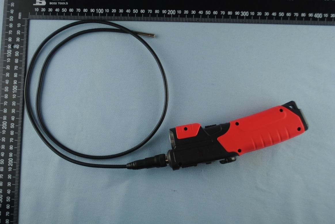
SWTIC-510S
Aug 31, 2015WiFi Video Scope
Equipment Class
DTS - Digital Transmission System
SWTTG-510
Aug 31, 2015Tire Pressure/Tread Depth gauge with Bluetooth
Equipment Class
DTS - Digital Transmission System