SWUDE-ABCM-SSMART CARD READER
Duali Inc.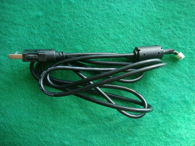
Click to zoom
Application Details
- Equipment Class
- JBP - Part 15 Class B Computing Device Peripheral
- Date of Grant
- Oct 23, 2011
- Application Purpose
- Original Equipment
- Date of Application
- Oct 23, 2011
- Equipment Note
- SMART CARD READER
- Company
- Duali Inc.
- Country
- South Korea
Documents & Files
Document Text
Text extracted from the exhibit documents filed with the FCC. Open a document above to read the original.
Users Manual
Copyright ⓒ 2009 DUALi Inc. All rights reserved. You are strictly prohibited to copy, disclose, distribute, or use this document in part or as a whole for any purposes other than those for which this document is disclosed. This document is copyrighted and contains confidential information and other intellectual property rights of DUALi Inc. Any unauthorized use, copy, disclosure or distribution constitutes infringement of DUALi’s intellectual property rights. DUALi Inc. Document Version: 1.02 Last Revised Date: 8 TH August 2011 DE-ABCM User Manual DUALi Inc. reserves the right to make changes to its applications or services or to discontinue any application or service at any time without notice. DUALi provides customer assistance in various technical areas, but does not have full access to data concerning the use and applications of customer's products. Therefore, DUALi assumes no liability and is not responsible for customer applications or software design or performance relating to systems or applications incorporating DUALi products. In addition, DUALi assumes no liability and is not responsible for infringement of patents and/or any other intellectual or industrial property rights of third parties, which may result from assistance provided by DUALi. Composition of the information in this manual has been done to the best of our knowledge. DUALi does not guarantee the correctness and completeness of the details given in this manual and may not be held liable for damages ensuing from incorrect or incomplete information. Since, despite all our efforts, errors may not be completely avoided, we are always grateful for your useful tips. We have our development center in South Korea to provide technical support. For any technical assistance can contact our technical support team as below; Tel: +82 31 213 0074 e-mail : [email protected] DE-ABCM User Manual Version. 1.02 DUALi Inc. (http://www.duali.com) 3 Revision History ■ 2009.04.09 : Issued first ■ 2011.07.18 : Add PCB dimension ■ 2011.08.08 : Add SAM card connectors’ specification DE-ABCM User Manual Version. 1.02 DUALi Inc. (http://www.duali.com) 4 Contents 1 Summary .......................................................................................................................................... 5 2 Structure ........................................................................................................................................... 5 2.1 The Structure of equipment .................................................................................................... 5 2.2 The block diagram of main Module, sub board(Epass12) and antenna ................................ 6 2.3 Description of main Module.................................................................................................... 6 3 Description of Surface ...................................................................................................................... 7 3.1 The picture of device surface ................................................................................................. 7 3.2 The size of equipment surface ...............................................................................................7 4 Connector pin assignment ................................................................................................................ 8 4.1 USB Connector ...................................................................................................................... 8 4.2 RS-232 Connector..................................................오류! 책갈피가 정의되어 있지 않습니다. 4.3 SAM1 Connector .................................................................................................................... 8 4.4 Header for IC CARD Connector and IC CARD Detection...................................................... 8 5 Description of electricity.................................................................................................................... 9 5.1 The Description of power ....................................................................................................... 9 5.2 The using electric current ....................................................................................................... 9 5.3 The Description of USB communication ................................................................................ 9 6 Description of Function ..................................................................................................................... 9 6.1 Protocol Specification ............................................................................................................. 9 6.2 Control Code Specification ..................................................................................................... 9 6.3 Download ............................................................................................................................... 9 7 Property ............................................................................................................................................ 9 7.1 Environment to use ................................................................................................................ 9 7.2 Environment to keep .............................................................................................................. 9 8 Warning and Notice .......................................................................................................................... 9 DE-ABCM User Manual Version. 1.02 DUALi Inc. (http://www.duali.com) 5 1 Summary Smart Card Interface Contactless Smart Card (ISO 14443 A/B), MIFARE, FeliCa 2 SAM CARD (ISO7816, T=0,T=1) Host Interface USB 2.0 Full Speed (12Mbps), also support USB 1.1 RS-232, 57600bps Host Communication PC/SC or Proprietary CPU ARM 32-bit Cortex-M3(72MHz), 64Kbytes Flash, 20Kbytes SRAM Power Voltage 5V, USB Bus powered Current MAX 300mA depend on antenna size Connection 4pin * 2m…
Text truncated - open the document above for the full version.
Cover Letter(s)
DUALi Inc. 1-309 Innoplex, 552 Woncheon-dong, Youngtong-gu, Suwon, Gyeonggi-do South Korea TEL: +82-31-213-0074, FAX: +82-31-213-0078 http://www.duali.com/ October 11, 2011 Federal Communications Commission Equipment Authorization Division, Application Processing Branch 7435 Oakland Mills Road Columbia, MD21046 RE: LETTER OF AGENT AUTHORIZATION We, the undersigned, hereby authorize SK TECH Co., Ltd.(Mr. Jongsoo, Yoon) to act on our behalf in all matters relating to application for equipment authorization. We also hereby certify that no party to the application authorized hereunder is subject to the denial of benefits, including FCC benefits, pursuant to Section 5301 of the Anti-Drug Abuse Act of 1988, 21 U.S.C.853(a). APPLICANT/AGENT CERTIFICATION AND AGREEMENT: All of the statements herein and the exhibits attached hereto, are true and correct to the best of my knowledge and belief. In accepting a Grant of Equipment Authorization issued by the TCB, under the authority of the FCC, as a result of the representations made in this application, the applicant is responsible for (1) labeling the equipment with the exact FCC ID specified in this application, (2) compliance statement labeling pursuant to the applicable rules, and (3) compliance of the equipment with the applicable technical rules. If the applicant is not the actual manufacturer of the equipment, appropriate arrangements have been made with the manufacturer to ensure that production units of this equipment will continue to comply with the FCC’s technical requirements. Authorizing an agent to sign this application, is done solely at the applicant’s discretion; however, the applicant remains responsible for all statements in this application. Sincerely, Ha Tae Yang/ Director
Cover Letter(s)
DUALi Inc. 1-309 Innoplex, 552 Woncheon-dong, Youngtong-gu, Suwon, Gyeonggi-do South Korea TEL: +82-31-213-0074, FAX: +82-31-213-0078 http://www.duali.com/ October 11, 2011 Federal Communications Commission Equipment Authorization Division, Application Processing Branch 7435 Oakland Mills Road Columbia, MD21046 TO WHOM IT MAY CONCERN Pursuant to Paragraphs §0.457 and 0.459 of the Commission's Rules (47 C.F.R) and Section §552(b)(4) of the Freedom of Information Act, DUALi Inc. requests confidentiality for the following products: FCC ID Number Product Description (Model) SWUDE-ABCM-S SMART CARD READER(DE-ABCM) The requested Permanent and Short-Term Confidential exhibits art listed as follows: PERMANENT AND SHORT-TERM CONFIDENTIAL LIST Exhibit Description 1 Block Diagram 2 Operational Description 3 Schematics PERMANENT 4 Part List No other items submitted as part of the equipment authorization filing process are deemed confidential. The above exhibits contain DUALi Inc. trade secrets and proprietary information that could be of benefit to our competitors regarding the design of our products. This material is not customarily available to the general public and we request that it be withheld from public inspection. Sincerely, Ha Tae Yang/ Director
Cover Letter(s)
DUALi Inc. 1-309 Innoplex, 552 Woncheon-dong, Youngtong-gu, Suwon, Gyeonggi-do South Korea TEL: +82-31-213-0074, FAX: +82-31-213-0078 http://www.duali.com/ October 11, 2011 Federal Communications Commission Equipment Authorization Division, Application Processing Branch 7435 Oakland Mills Road Columbia, MD21046 RE: PART 15 UNLICENSED MODULAR TRANSMITTER APPROVAL TO WHOM IT MAY CONCERN We, DUALi Inc., he reby re quests f or part 1 5 u nlicensed l imited modular t ransmitter ap proval of our DE-ABCM module, described as follows: Model name: DE-ABCM FCC ID: SWUDE-ABCM-S 1. The modular transmitter must have its own shielding. The product is a complete RF transmitter. The product does have its own shielding. 2. The modular transmitter must have buffered modulation/data inputs The module has a memory management unit inside of the main IC. It buffers the data inputs from USB interface. 3. The modular transmitter must have its own power supply regulation The EUT contains USB interface (DC 5 V input) and own low noise LDO regu lator (U3). In case of ch anges in the supp ly voltage VCC (for example caused by temperature changes or other effects), the internal voltage will be stabilized. 4. The modular transmitter must comply with the antenna requirements of Section 15.203 and 15.204 The transmitter shall only be used with the tested antenna that is integral PCB antenna. 5. The modular transmitter must be tested in a stand-alone configuration The EUT was tested in a stand -alone configuration. The module was conn ected with the notebook PC via USB interf ace, during the test. See also the test report and Test setup photos. 6. The modular transmitter must be labeled with its own FCC ID number The EUT will be labeled with its own FCC ID number. The label is specified in Label Information document. If the module is installed inside of an end-product, the label will not be visible. In this case the OEM customer will be instructed to how to apply the exterior label. 7. AC, DC, and data input/output lines must not contain ferrites, unless they will be marketed with the module. The EUT contains ferrites on the USB cable, however the USB cable will be marketed with the module. 8. The modular transmitter must comply with any specific rule or operating requirements The EUT is compliant with all applicable FCC rules. Detail instructions are given in the product Instruction Manual. 9. The modular transmitter must comply with any applicable RF exposure requirements. The EUT is a 13.56 MHz RFID device, and radiates extremely low RF power level. It is categorically excluded from RF exposure requirements. Sincerely, Ha Tae Yang/ Director
External Photos
SK TECH CO., LTD. Page 1 of 2 SKTRFC-111011-024 FCC ID: SWUDE-ABCM-S External Photographs of EUT <Photograph 1: Front View> <Photograph 2: Rear View> SK TECH CO., LTD. Page 2 of 2 SKTRFC-111011-024 FCC ID: SWUDE-ABCM-S < Photograph 3: External - USB cable> <Photograph 4: RFID tag tested with the EUT> Front view (A type) Rear view (A type) Front view (B type) Rear view (B type)
ID Label/Location Info
ID Label Location & Sample LABEL LOCATION: Label will be attached to the Rear of the product LABEL Drawing:
ID Label/Location Info
ID Label Location & Sample LABEL LOCATION: Label will be attached to the Rear of the product LABEL Drawing:
Internal Photos
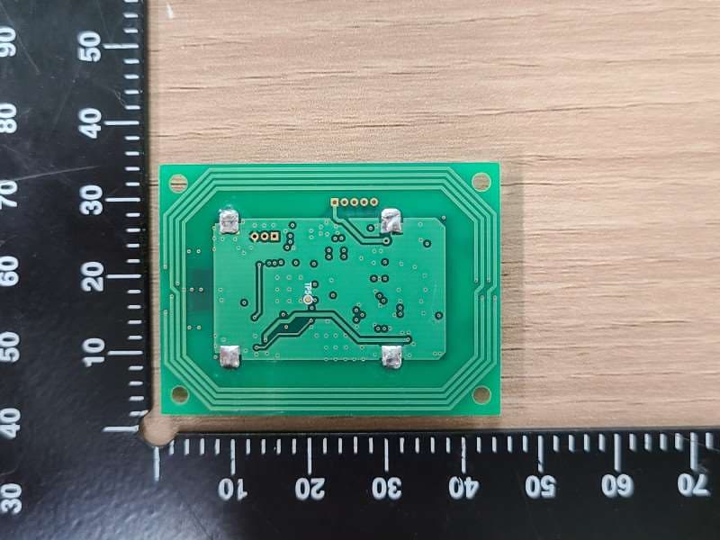
SK TECH CO., LTD. Page 1 of 2 SKTRFC-111011-024 FCC ID: SWUDE-ABCM-S Internal Photographs <Photograph 1: RF board - Front view> SK TECH CO., LTD. Page 2 of 2 SKTRFC-111011-024 FCC ID: SWUDE-ABCM-S <Photograph 2: RF board- Front view(Shielding remove> SK TECH CO., LTD. Page 3 of 2 SKTRFC-111011-024 FCC ID: SWUDE-ABCM-S <Photograph 3: RF board - Rear view> RFID ANTENNA
Test Report
SK Tech Co., Ltd. http://www.skemc.co.kr SKTEFC-111011-120 SK Tech Co., Ltd. 820-2, Wolmoon-Ri, Wabu-Up Namyangju-Si, Kyunggi-Do, 472-905, Korea Phone: +82-31-576-2204 Fax: +82-31-576-2205 Page 2 of 47 REVISION HISTORY Rev. # Changes of Content Section Affected Reviewed by Date 0 Original Release All S.H.Yoon Oct. 11. 2011 SK Tech Co., Ltd. http://www.skemc.co.kr SKTEFC-111011-120 SK Tech Co., Ltd. 820-2, Wolmoon-Ri, Wabu-Up Namyangju-Si, Kyunggi-Do, 472-905, Korea Phone: +82-31-576-2204 Fax: +82-31-576-2205 Page 3 of 47 SUMMARY OF TEST RESULT EMISSION STANDARD ITEM CLASS/SEVERITY RESULT AC Power line Conducted Emission Test Meets Class B limits and minimum passing margin is 13.53 dB at 1.160 MHz. PASS ANSI C63.4 / 2009 FCC Part 15 Subpart B Radiated Emission Test Meets Class B limits and minimum passing margin is 11.06 dB at 433.90 MHz. PASS SK Tech Co., Ltd. http://www.skemc.co.kr SKTEFC-111011-120 SK Tech Co., Ltd. 820-2, Wolmoon-Ri, Wabu-Up Namyangju-Si, Kyunggi-Do, 472-905, Korea Phone: +82-31-576-2204 Fax: +82-31-576-2205 Page 4 of 47 》 Table of Contents 《 i Cover Page 1 ii Revision History 2 iii Summary of Test Results 3 IV Table of Contents 4 1. General 5 2. Facilities and Accreditations 5 2.1 Facilities 5 2.2 Accreditations 5 2.3 Test and Measurement Instruments Used 6 3. EUT Description 7 4. EUT Operating Condition 8 4.1 EUT Operating Modes 8 4.2 Ancillary Equipment 8 4.3 Interconnection and I/O cable 9 4.4 Configuration 10 4.5 Uncertainty 11 5. Test Results EMISSION 12 5.1 Conducted Disturbance at mains terminals 12 5.2 Radiated Disturbance 15 Appendices A1 Photographs of the test set-up 18 A2 EUT Photographs 20 SK Tech Co., Ltd. http://www.skemc.co.kr SKTEFC-111011-120 SK Tech Co., Ltd. 820-2, Wolmoon-Ri, Wabu-Up Namyangju-Si, Kyunggi-Do, 472-905, Korea Phone: +82-31-576-2204 Fax: +82-31-576-2205 Page 5 of 47 1. General The tests listed in this report have been performed and the results recorded by SK Tech Co., Ltd. in accordance with the procedures stated in each test requirement and specification. As a result, the subject product has been verified to comply with each test specification. The test results relate only to the items tested. We attest to the accuracy of data. All measurements reported herein were performed by SK TECH Co., Ltd. and were made under Technical Manager’s supervision. We assume full responsibility for the completeness of these measurements and vouch for the qualifications of all persons taking them. 2. Facilities and Accreditations 2.1 Facilities All of the measurements described in this report were performed at SK Tech Co., Ltd located in 820-2, Wolmoon Ri, Wabu-Up, Namyangju-Si, Kyunggi-Do, Korea. The test site is constructed in conformance with the requirements of ANSI C63.4 and CISPR Publication 22. It complies with the Normalized Site Attenuation requirements given in ANSI/IEEE C63.4. The measuring equipment conforms to CISPR 16 requirements for Electromagnetic Noise and Field Strength Instrumentation. 2.2 Accreditations Our testing laboratories are accredited by the following accreditation bodies in accordance with ISO/IEC 17025 for general requirements for the competence of testing and calibration laboratories. Korea : KOLAS No.191 Germany : DAKKS DAT-P-076/97-02 USA : NVLAP Lab Code: 200220-0 The laboratories have been also notified to FCC by RRL as a Conformity Assessment Body, and designated to perform compliance testing on equipment subject to Declaration of Conformity (DOC) and Certification under Parts 15 and 18 of the FCC Rules. SK Tech Co., Ltd. http://www.skemc.co.kr SKTEFC-111011-120 SK Tech Co., Ltd. 820-2, Wolmoon-Ri, Wabu-Up Namyangju-Si, Kyunggi-Do, 472-905, Korea Phone: +82-31-576-2204 Fax: +82-31-576-2205 Page 6 of 47 2.3 Test and Measurement Instruments Used •Conducted Disturbance Name of Equipment Type S/N Calibrated until EMI Receiver ESHS10 862970/019 07.2012 Artificial Mains Network ESH2-Z5 834549/011 07.2012 Artificial Mains Network ESH3-Z5 836679/018 07.2012 Impedance Stabilization Network ISN T8 24806 02.2012 •Radiated Disturbance Name of Equipment Type S/N Calibrated until EMI Receiver ESVS40 100277 07.2012 Amplifier 8447F 3113A05153 07.2012 Trilog-Broadband Antenna VULB9168 9168-230 05.2012 Antenna Turntable Driver 5907 91X518 N/A Antenna Turntable controller 5906 91X519 N/A EMI TEST RECEIVER ESPI 101206 07.2012 Log-Periodic Antenna LP960-2 A080510 01.2012 Pre-Amplifier MLA-100M18-B02- 38 1539546 03.2012 SK Tech Co., Ltd. http://www.skemc.co.kr SKTEFC-111011-120 SK Tech Co., Ltd. 820-2, Wolmoon-Ri, Wabu-Up Namyangju-Si, Kyunggi-Do, 472-905, Korea Phone: +82-31-576-2204 Fax: +82-31-576-2205 Page 7 of 47 3. EUT Description The following information has been supplied by the applicant. Product Specification Smart Card Interface Contactless Smart Card (ISO 14443 A/B), MIFARE, FeliCa 2 SAM CARD (ISO7816, T=0,T=1) Host Interface USB 2.0 Full Speed (12Mbps), also support USB 1.1 Host Communication PC/SC or Proprietary CPU ARM 32-bit Cortex-M3(72MHz), 64Kbytes Flash, 20Kbytes SRAM Input Voltage 5V, USB Bus powered Transmitting frequency 13.56 MHz (nominal) Current MAX 250mA depend on antenna size Connection 4 pin * 2 mm for USB 5 pin * 2 mm for RS-232 Size 70(W) * 45(L) * 8(H)mm Antenna Matching Direct matching Operating Temperature -20~60°C SK Tech Co., Ltd. http://www.skemc.co.kr SKTEFC-111011-120 SK Tech Co., Ltd. 820-2, Wolmoon-Ri, Wabu-Up Namyangju-Si, Kyunggi-Do, 472-905, Korea Phone: +82-31-576-2204 Fax: +82-31-576-2205 Page 8 of 47 4. EUT Operating Conditions During testing, the EUT was powered with, DC 5 V USB Bus. The worst case test configuration and mode of operation was used all testing. Unless otherwise noted elsewhere in this report, this selection will apply to all testing. 4.1 EUT Operation Modes The EUT is connected to the PC, and run the test program. Then, put the RFID card on the EUT. Check the connection between EUT and PC through test program. In the testing mode (TYPE A RFID card and TYPE B RFID card), th…
Text truncated - open the document above for the full version.
Test Setup Photos
SK TECH CO., LTD. Page 1 of 2 SKTEFC-111011-120 FCC ID: SWUDE-ABCM-S Test set up photos <Radiated Emissions - Front View> <Radiated Emissions - Rear View> SK TECH CO., LTD. Page 2 of 2 SKTEFC-111011-120 FCC ID: SWUDE-ABCM-S <AC Power Line Conducted Emissions - Front View> <AC Power Line Conducted Emissions - Rear View>
Contact Information
Applicant
Ha Tae-Yang(Team Manager)
Test Firm
SK Tech Co., LTD.Yoon Jongsoo
Technical Specifications
| # | Rule Parts | Frequency Range | Power Output |
|---|---|---|---|
| 1 | 15B | - | - |
Other Applications from Duali Inc.
SWUDEABM7
Jun 20, 2022DXX
Equipment Class
DXX - Part 15 Low Power Communication Device Transmitter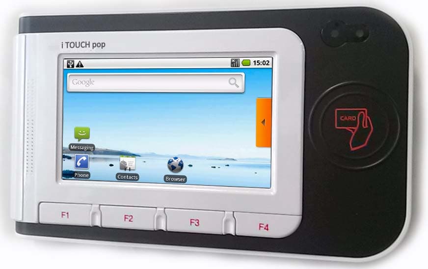
SWUITOUCHPOPV2
Jun 29, 2015SMART CARD READER
Equipment Class
DTS - Digital Transmission System
SWUBLP-A04-NR06
May 28, 2015Smart Card Reader
Equipment Class
DXX - Part 15 Low Power Communication Device Transmitter
SWUDE-632
Aug 27, 2014SMART CARD READER
Equipment Class
DXT - Part 15 Low Power Transceiver, Rx Verified
SWUDE-930
Dec 25, 2012SMART CARD READER
Equipment Class
DXT - Part 15 Low Power Transceiver, Rx Verified