SWUDE-EPASS10PASSPORT READER
Duali Inc.
Click to zoom
Application Details
- Equipment Class
- JBP - Part 15 Class B Computing Device Peripheral
- Date of Grant
- May 31, 2011
- Application Purpose
- Original Equipment
- Date of Application
- May 30, 2011
- Equipment Note
- PASSPORT READER
- Company
- Duali Inc.
- Country
- South Korea
Documents & Files
Document Text
Text extracted from the exhibit documents filed with the FCC. Open a document above to read the original.
Users Manual
Copyright ⓒ 2010 DUALi Inc. All rights reserved. You are strictly prohibited to copy, disclose, distribute, or use this document in part or as a whole for any purposes other than those for which this document is disclosed. This document is copyrighted and contains confidential information and other intellectual property rights of DUALi Inc. Any unauthorized use, copy, disclosure or distribution constitutes infringement of DUALi’s intellectual property rights. DUALi Inc. Document Version: 1.0 Last Revised Date: 07.Dec. 2010 DE-EPASS10 User Manual DUALi Inc. reserves the right to make changes to its applications or services or to discontinue any application or service at any time without notice. DUALi provides customer assistance in various technical areas, but does not have full access to data concerning the use and applications of customer's products. Therefore, DUALi assumes no liability and is not responsible for customer applications or software design or performance relating to systems or applications incorporating DUALi products. In addition, DUALi assumes no liability and is not responsible for infringement of patents and/or any other intellectual or industrial property rights of third parties, which may result from assistance provided by DUALi. Composition of the information in this manual has been done to the best of our knowledge. DUALi does not guarantee the correctness and completeness of the details given in this manual and may not be held liable for damages ensuing from incorrect or incomplete information. Since, despite all our efforts, errors may not be completely avoided, we are always grateful for your useful tips. We have our development center in South Korea to provide technical support. For any technical assistance can contact our technical support team as below; Tel: +82 31 213 0074 e-mail : [email protected] DE-EPASS10 Specification Version 1.0 DUALi Inc. (http://www.duali.com) 3 Revision History n 2010.12.07(Ver. 1.0) : First Release DE-EPASS10 Specification Version 1.0 DUALi Inc. (http://www.duali.com) 4 CONTENTS 1. Concept.......................................................................................................................................5 2. Configuration..............................................................................................................................6 2.1 configuration of the DE-EPASS10.....................................................................................6 2.2 System configuration...........................................................................................................6 2.3 RF Main Block and Description........................................................................................7 2.4 OCR Reader Module............................................................................................................7 3. Exterior Specification..............................................................................................................8 3.1 exterior................................................................................................................................8 3.2 size.......................................................................................................................................8 4. Electric Specification...................................................................................................................9 4.1 power...................................................................................................................................9 4.2 power consumption:............................................................................................................9 4.3 USB communication................................................................................................................9 5. Environmental Specification........................................................................................................9 5.1 operating temperature and humidity..................................................................................9 5.2 storage temperature and humidity.....................................................................................9 6. Warning and Precaution.............................................................................................................10 DE-EPASS10 Specification Version 1.0 DUALi Inc. (http://www.duali.com) 5 1. Concept The Passport Reader issued a PC on the ICAO 9303 standard for passport information to be used for reading as a reader, ISO-14443 A / B-type card reader for reading and writing, and high-precision image and optical character reading is possible. Communication with the USB interface to USB 2.0 are supported Depending on your needs SAM / SIM support is available OCR Reader Window Size 130 mm x 60 mm Window Glass 4 mm glass Image Resolution 350 dpi Color Depth 24 bits/pixel RGB Output Image format BMP,JPEG,JPEG2000,PNG Illuminations White light(default),IR(optional) OCR Reading Speed Capture 0.1sec,Processing 0.9sec MRZ processing Supporting(ISO 1073/1 OCR B1) RF Reader Readable ICs ISO/IEC 14443 Type A & B(106,212,424,848kbps) Data structure and read protocol Comply to ICAO 9303 Part 1 Access/Authentication BAC,PA supporting,(AA,EAC-Optional) Auto-detection Doc. Supporting Environment Host Communication USB 2.0(Full Speed,12M) Power DC 12V/300mA Temperature 0~40ºC(Operating),-20~50ºC(Storage) Humidity 0~95 % Dimension 179 mm x 172 mm x 94 mm DE-EPASS10 Specification Version 1.0 DUALi Inc. (http://www.duali.com) 6 2. Configuration 2.1 configuration of the DE-EPASS10 - RF card reader and antenna sub-board module - ARH OCR reader module (mirror, sensor, light panel included) - Power and Control Module, USB HUB - Internal / External Cable 2.2 System configuration DE-EPASS10 Specification Version 1.0 DUALi Inc. (http://www.duali.com) 7 2.3 RF Main Block and Description - CPU: ARM 32-bit Cortex-M3 (48MHz) and the 128Kbytes Flash, 20Kbyt…
Text truncated - open the document above for the full version.
ID Label/Location Info
ID Label/Location Information This device complies with Part 15 of the FCC Rules. Operation is subject to the following two conditions: (1) this device may not cause harmful interference, and (2) this device must accept any interference received, including interference that may cause undesired operation.
Operational Description
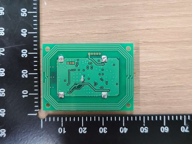
PCB Loop Antenna
Schematics
DE-EPASS_PWRHUB 보드 TOP side 부품배치도 DE-EPASS_PWRHUB 보드 Bottom side 부품배치도 DE-EPASS_MAIN TOP side Part Location Diagram DE-EPASS_MAIN BOTTOM side Part Location Diagram DE-EPASS_SUB TOP side Part Location Diagram DE-EPASS_SUB BOTTOM side Part Location Diagram 내부 메인 보드 전면 메인 보드 후면 서브 보드 전면 서브 보드 후면 전원 보드 전면 전원 보드 후면 카메라 보드 전면 카메라 보드 후면 LED 보드 전면 LED 보드 후면
Test Report
IST Co., Ltd. TEST REPORT NO. : 11-IST-0481 1 of 13 IST(02) 029 A4 모(101025) Declaration of Compliance CFR 47 Part 15 Subpart B Test Report File No. 11-IST-0481 ■ Basic □ Alternate Date of Receipt Mar. 02, 2011 Begin of test date April 28, 2011 Date of Issue May. 13, 2011 End of test date April 29, 2011 Kind of Product Passport Reader Basic Model(s) DE-EPASS10 FCCID SWUDE-EPASS10 Applicant DUALi Inc. Address #505, Samsung Technopark, 471, Woncheon-Dong, Yungtong-Gu, Suwon-Si, Gyeonggi-Do, Korea Manufacturer DUALi Inc. Address #505, Samsung Technopark, 471, Woncheon-Dong, Yungtong-Gu, Suwon-Si, Gyeonggi-Do, Korea Standard Section 15.107, Section 15.109 [Class A Equipment] Test Result ■ Positive Negative Tested By Reviewed By Uihyun Ryu / Senior Engineer B.S.KIM / Chief Comment(s) - Investigations requested : Measurement to the relevant clauses of FCC rules and regulations Part 15 Subpart B – Unintentional Radiators, Class B. - The test report with appendix consists of 16 pages. - The test result only responds to the tested sample. - It is not allowed to copy this report even partly without the allowance of IST EMC Laboratory. - This equipment as for has been shown to be capable of continued compliance with the applicable technical standards as indicated in the measurement report and was tested in accordance with the measurement procedures specified in ANSI C63.4 2003. IST Co., Ltd. TEST REPORT NO. : 11-IST-0481 2 of 13 IST(02) 029 A4 모(101025) TABLE OF CONTENTS Table of contents 2 Information of test laboratory, Environmental conditions, Power supply system used, Product information 3 Descriptions of test 4-5 Conducted Emission 4 Radiated Emission 5 Equipment Under Test 6-7 Summary 8 ■ Test Conditions and Data - Emissions ◆ Conducted Emissions 0.15 MHz - 30 MHz Applicable Test Conditions / Data and Plots 9-11 ◆ Radiated Emissions 30 MHz - 1 GHz Applicable Test Conditions / Data and Plots 12-13 Appendix A. The Photos of Test Setup 14-16 Note: IST Co., Ltd. TEST REPORT NO. : 11-IST-0481 3 of 13 IST(02) 029 A4 모(101025) INFORMATIONS OF TEST LABORATORY IST Co., Ltd. 400-19, Singal-dong, Giheung-gu, Yongin-si, Kyonggi-Do, 446-599, Korea TEL : +82 31 326 6700 FAX : +82 31 326 6797 KOLAS Testing No. : 118 RRA Designation No. : KR0018 FCC Registration No. : 400603 FCC(DoC) Registration No. : 801060 VCCI Member No. : 1739 POWER SUPPLY SYSTEM USED Power supply system 120 V, 60 Hz (Refer to the product information) PRODUCT INFORMATION OCR Reader Window Size 130 mm x 60 mm Window Glass 4 mm glass Image Resolution 350 dpi Color Depth 24 bits/pixel RGB Output Image format BMP,JPEG,JPEG2000,PNG Illuminations White light(default),IR(optional) OCR Reading Speed Capture 0.1sec,Processing 0.9sec MRZ processing Supporting(ISO 1073/1 OCR B1) RF Reader Readable ICs ISO/IEC 14443 Type A & B(106,212,424,848kbps) Data structure and read protocol Comply to ICAO 9303 Part 1 Access/Authentication BAC,PA supporting,(AA,EAC-Optional) Auto-detection Doc. Supporting Dimension 179 mm x 172 mm x 94 mm - Please refer to user’s manual. IST Co., Ltd. TEST REPORT NO. : 11-IST-0481 4 of 13 IST(02) 029 A4 모(101025) < Concept Drawing > 215 >150 >40 80 Receiver EUT LISN 80 ³ 80 80 40 ³ 80 Measuring apparatus Mains Filter Mains Front side Equipment under test Coaxial cable Artificial mains network Screened room Non-metallic support 80 DESCRIPTIONS OF TEST Conducted Emissions: The measurement were performed over the frequency range of 0.15 MHz to 30 MHz using a 50 Ω /50uH LISN as the input transducer to a Spectrum Analyzer or a Field Intensity Meter. The measurements were made with the detector set for "Peak" amplitude within a bandwidth of 10KHz or for "quasi-peak" & “Average” within a bandwidth of 9 KHz. - Procedure of Test The line-conducted facility is located inside a shielded room No.1. A 1 m X 1.5 m wooden table 80 cm height is placed 40 cm away from the vertical wall and 1.5 m away from the other wall of the shielded room. The R/S ESH3-Z5 and Hyup-Rip KNW-407 LISN are bonded to bottom of the shielded room. The EUT is located on the wooden table with distance more than 80 cm from the LISN and powered from the Hyup-Rip LISN. The peripheral equipment is powered from the other LISN. Power to the LISNs are filtered by a noise cut power line filters. All electrical cables are shielded by braided tinned steel tubing with inner f 1.2 cm. If the EUT is a DC-powered device, power will be derived from the source power supply it normally will be powered from and this supply lines will be connected to the Hyup-Rip LISN. All interconnected cables more than 1 m were shortened by non-inductive bundling to a 1 m length. Sufficient time for the EUT, support equipment, and test equipment was allowed in order for them to warm up to their normal operating conditions. The RF output of the LISN was connected to the R/S receiver to determine the frequency producing the maximum emission from the EUT. The frequency producing the maximum level was reexamined using Quasi-Peak mode by manual measurement, after scanned by automatic Peak mode for frequency range from 0.15 to 30 MHz. The bandwidth of the receiver was set to 10 kHz. The EUT, peripheral equipment, and interconnecting cables were arranged and manipulated to maximize each EME emission. < Side View > IST Co., Ltd. TEST REPORT NO. : 11-IST-0481 5 of 13 IST(02) 029 A4 모(101025) DESCRIPTION OF TEST Radiated Emissions: The measurement was performed over the frequency range of 30 MHz to 1 GHz using antenna as the input transducer to a Spectrum analyzer or a Field Intensity Meter. The measurement was made with the detector set for "quasi-peak" within a bandwidth of 120 KHz. - Procedure of Test Preliminary measurements were made at 3 meter using bi-conical and log-periodic antennas, and spectrum analyzer to determine the frequency producing the max. emission in anechoic chamber. Appropriate precaution was taken to ensure that all emission from the EUT were maximized and investigated. The system confi…
Text truncated - open the document above for the full version.
Contact Information
Applicant
Ha Tae-Yang(Team Manager)
Test Firm
IST Co., LtdCho Sung Jung
Technical Specifications
| # | Rule Parts | Frequency Range | Power Output |
|---|---|---|---|
| 1 | 15B | - | - |
Other Applications from Duali Inc.
SWUDEABM7
Jun 20, 2022DXX
Equipment Class
DXX - Part 15 Low Power Communication Device Transmitter
SWUITOUCHPOPV2
Jun 29, 2015SMART CARD READER
Equipment Class
DTS - Digital Transmission System
SWUBLP-A04-NR06
May 28, 2015Smart Card Reader
Equipment Class
DXX - Part 15 Low Power Communication Device Transmitter
SWUDE-632
Aug 27, 2014SMART CARD READER
Equipment Class
DXT - Part 15 Low Power Transceiver, Rx Verified
SWUDE-930
Dec 25, 2012SMART CARD READER
Equipment Class
DXT - Part 15 Low Power Transceiver, Rx Verified