SWX-M365P3.65-3.675 GHz 2x2 MIMO Bridge
Ubiquiti Inc.
Click to zoom
Application Details
- Equipment Class
- TNB - Licensed Non-Broadcast Station Transmitter
- Date of Grant
- May 01, 2011
- Application Purpose
- Original Equipment
- Date of Application
- Apr 23, 2011
- Equipment Note
- 3.65-3.675 GHz 2x2 MIMO Bridge
- Frequency Range
- 3662.00000000 - 3662.00000000
- Company
- Ubiquiti Inc.
- Country
- United States
Documents & Files
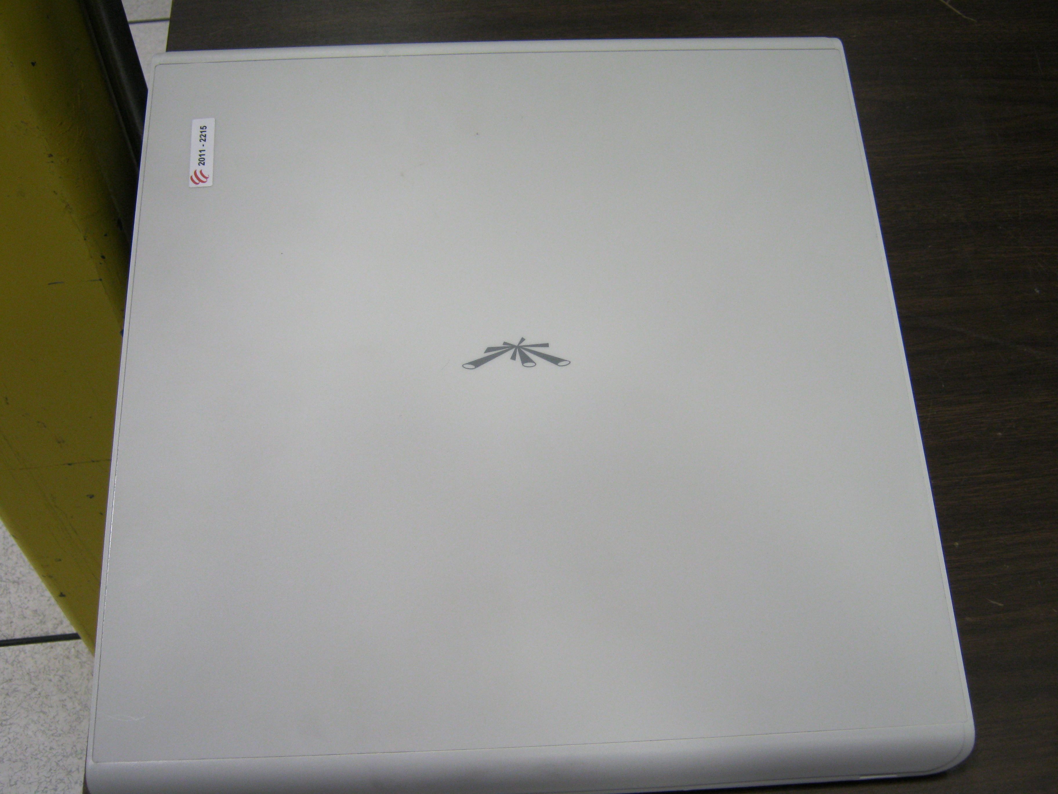
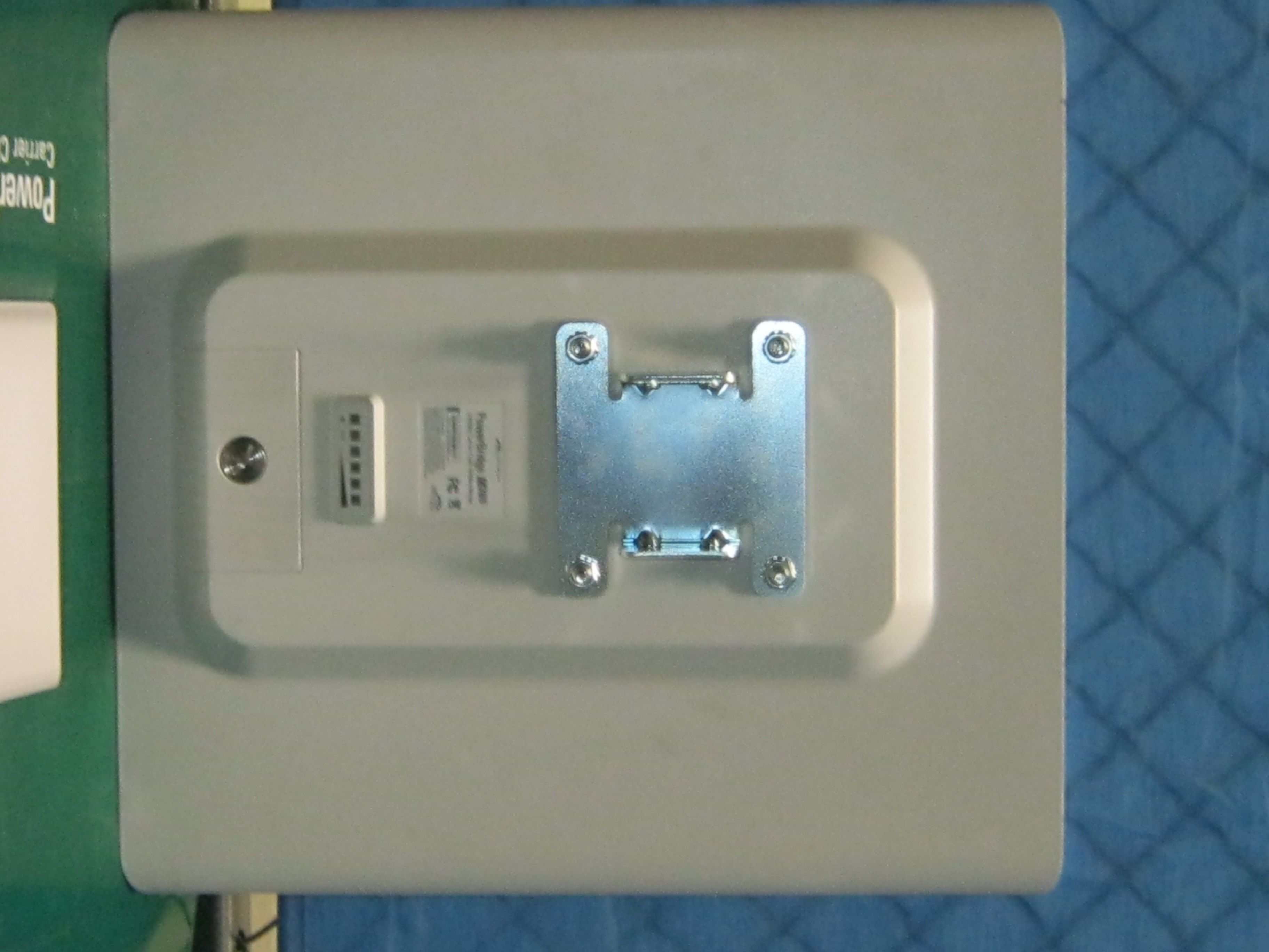
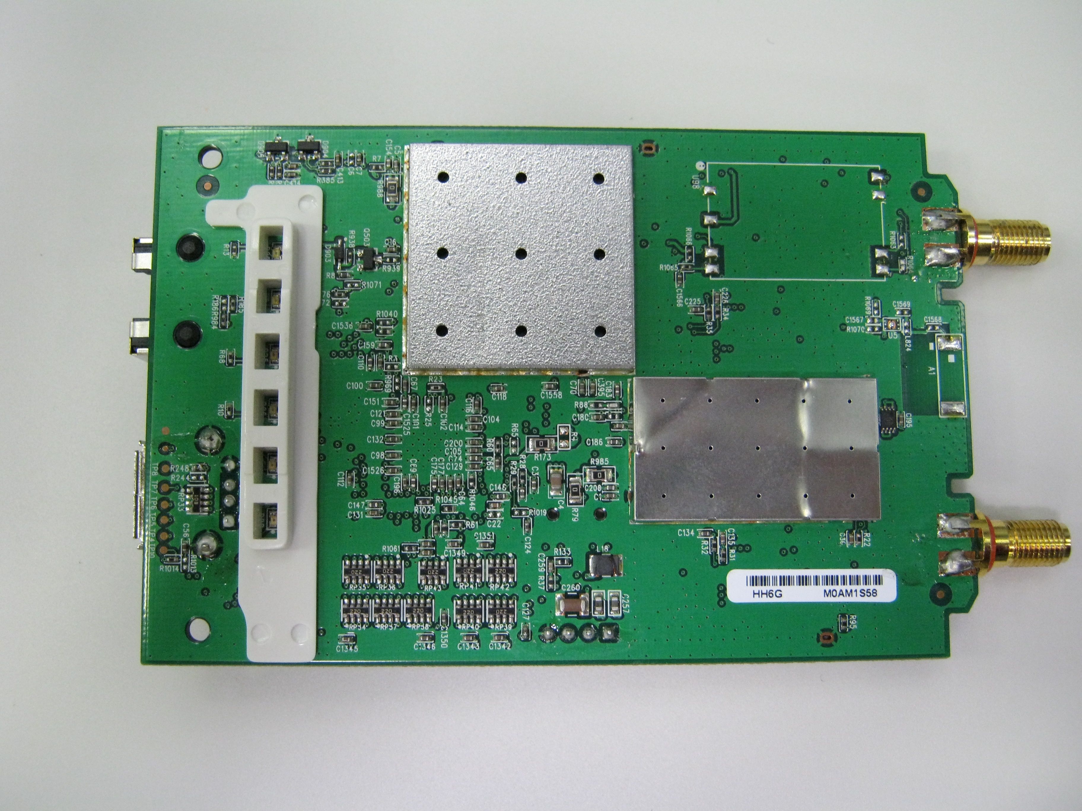
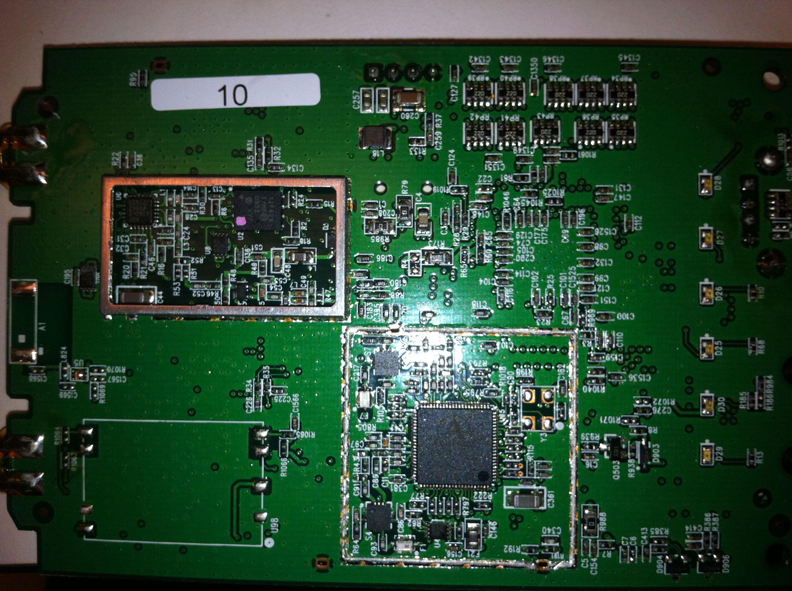
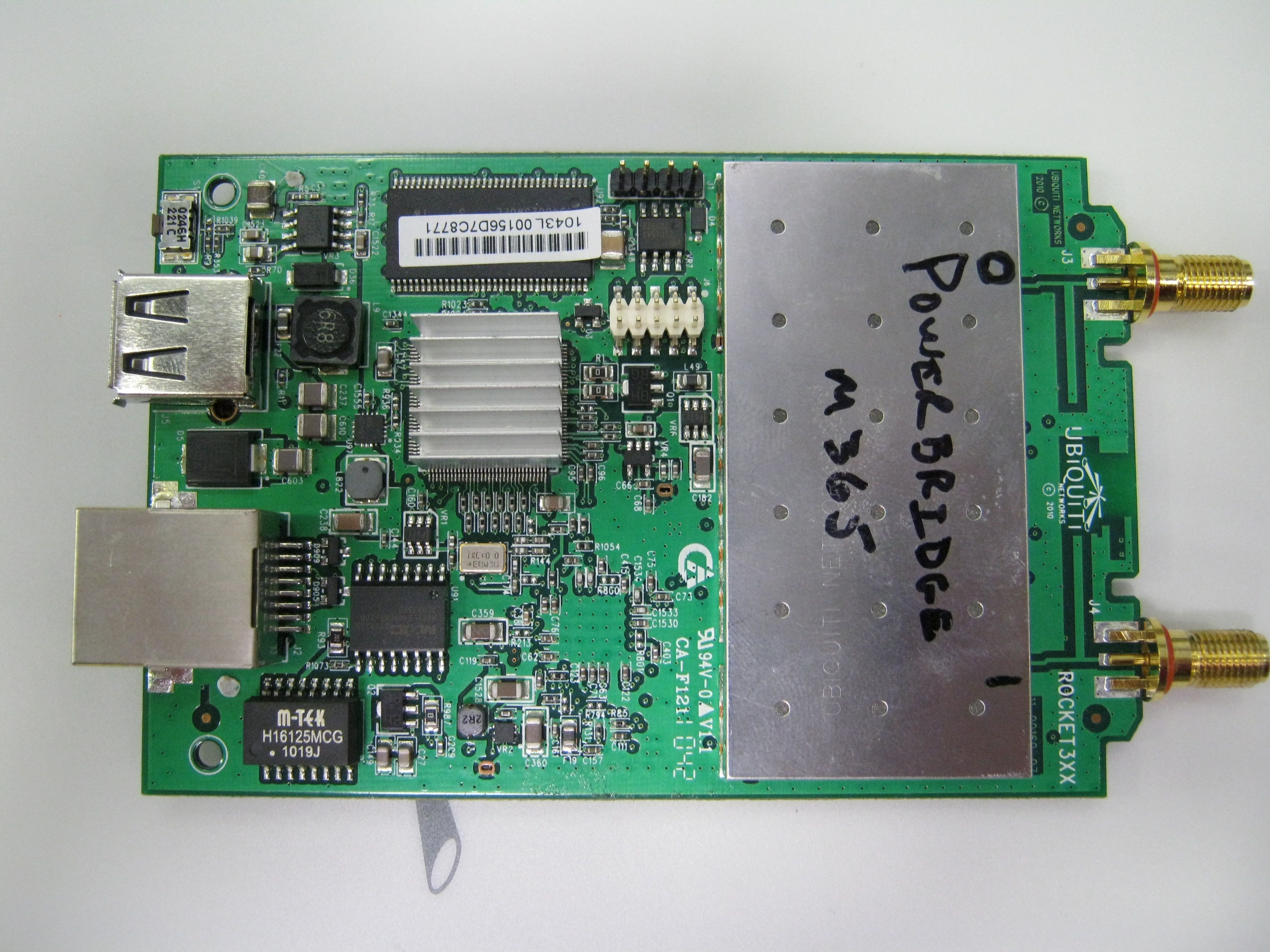
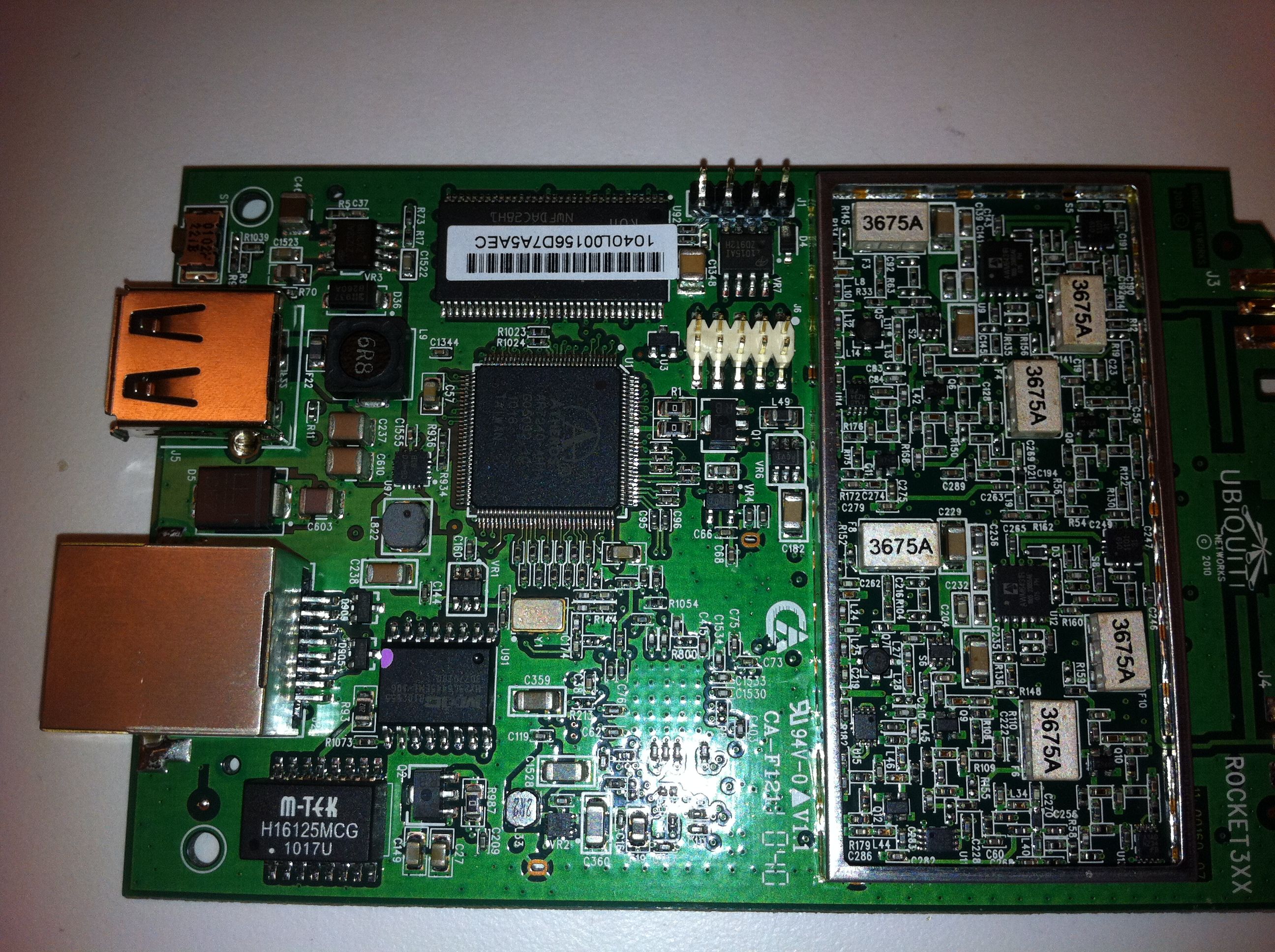
Document Text
Text extracted from the exhibit documents filed with the FCC. Open a document above to read the original.
Users Manual
Carrier Class AirMax BaseStation Models: M3/M365/M5 1 Package Contents Package Contents PowerBridge24V PoE AdapterPower CordAntenna Bracket Clamps (Qty. 2) Pole Bracket Clamps (Qty. 2) Serrated Flange Bolts (Qty. 4) Serrated Flange Lock Nuts (Qty. 4) M8X135 Carriage Bolts (Qty. 4) Carrier Class AirMax BaseStation Models: M3/M365/M5 Quick Start Guide Installation Requirements • Adjustable wrench or one 16 mm and one 24 mm wrench • Flathead screwdriver • Shielded Category 5 (or above) cabling should be used for all wired Ethernet connections and should be grounded through the AC ground of the PoE. We recommend that you protect your networks from the most brutal environments and devastating ESD attacks with industrial‑grade shielded Ethernet cable from Ubiquiti Networks. For more details, visit www.ubnt.com/toughcable 2 PowerBridge Hardware Installation To install the PowerBridge, perform the following steps: 1. Use a flathead screwdriver to unlock the PowerBridge case. Turn the screw counter‑clockwise until it is loose. The screw remains attached to the compartment. Comp liant R o H S 2. Lift the cover on the PowerBridge by pressing down and raising it up. Connect an Ethernet cable. There is an opening for the Ethernet cable. Slide the cover over the cable and secure it with the screw. 3 Hardware Installation 3. Insert the M8X135 Carriage Bolts into the Antenna Bracket Clamps. 4. Connect the Antenna Bracket Clamps to the PowerBridge using the four Serrated Flange Bolts. Comp liant R o H S 4 PowerBridge 5. Mount the PowerBridge to the pole by performing the following steps: a. Position the PowerBridge in the desired mounting location on the pole. b. Slide the Pole Bracket Clamps on to the Carriage Bolts. c. Use the four Serrated Flange Lock Nuts to secure the PowerBridge to the pole. Comp liant R o H S 5 Hardware Installation 6. Adjust the operating angle of the PowerBridge by adjusting the Serrated Flange Bolts on the top Antenna Bracket Clamp. Compliant R o H S 6 PowerBridge 7. Connect the other end of the Ethernet cable from the PowerBridge to the Ethernet port labeled POE on the PoE Adapter. Complia nt R o H S 7 Hardware Installation 8. Connect an Ethernet cable from your LAN to the Ethernet port labeled LAN on the PoE Adapter. 9. Connect the power cord to the power port on the PoE Adapter. Connect the other end of the power cord to a power outlet. 8 PowerBridge Accessing the AirOS Utility 1. Make sure that your host machine is connected to the LAN that is connected to the PowerBridge. 2. Configure the Ethernet adapter on your host system with a static IP address on the 192.168.1.x subnet (e.g. 192.168.1.100). 3. Launch your Web browser and type http://192.168.1.20 in the address field and press enter (PC) or return (Mac). 4. The login screen will appear. Enter ubnt in the Username and Password fields and click Login. The AirOS Interface will appear allowing you to customize your settings as needed. Congratulations! Installation is complete. 9 General Warranty General Warranty UBIQUITI NETWORKS, Inc (“UBIQUITI NETWORKS”) represents and warrants that the Products furnished hereunder shall be free from defects in material and workmanship for a period of one (1) year from the date of shipment by UBIQUITI NETWORKS under normal use and operation. UBIQUITI NETWORKS sole and exclusive obligation under the foregoing warranty shall be to repair or replace, at its option, any defective Product that fails during the warranty period. The expense of removal and reinstallation of any item is not included in this warranty. The foregoing warranty is exclusive and in lieu of all other warranties, express or implied, including the implied warranties of merchantability and fitness for a particular purpose and any warranties arising from a course of dealing, usage or trade practice with respect to the products. Repair or replacement in the manner provided herein shall be the sole and exclusive remedy of Buyer for breach of warranty and shall constitute fulfillment of all liabilities of UBIQUITI NETWORKS with respect to the quality and performance of the Products. UBIQUITI NETWORKS reserves the right to inspect all defective Products (which must be returned by Buyer to UBIQUITI NETWORKS factory freight prepaid). No Products will be accepted for replacement or repair without obtaining a Return Materials Authorization (RMA) number from UBIQUITI NETWORKS. Products returned without an RMA number will not be processed and will be returned to Buyer freight collect. UBIQUITI NETWORKS shall have no obligation to make repairs or replacement necessitated by catastrophe, fault, negligence, misuse, abuse, or accident by Buyer, Buyer’s customers or any other parties. The warranty period of any repaired or replaced. Product shall not extend beyond its original term. Warranty Conditions The foregoing warranty shall apply only if: (I) The Product has not been subjected to misuse, neglect or unusual physical, electrical or electromagnetic stress, or some other type of accident. (II) No modification, alteration or addition has been made to the Product by persons other than UBIQUITI NETWORKS or UBIQUITI NETWORK’S authorized representatives or otherwise approved by UBIQUITI NETWORKS. (III) The Product has been properly installed and used at all times in accordance, and in all material respects, with the applicable Product documentation. (IV) All Ethernet cabling runs use CAT5 (or above) shielded cabling. Disclaimer: UBIQUITI NETWORKS does not warrant that the operation of the products is error‑free or that operation will be uninterrupted. In no event shall UBIQUITI NETWORKS be responsible for damages or claims of any nature or description relating to system performance, including coverage, buyer’s selection of products for buyer’s application and/or failure of products to meet government or regulatory requirements. 10 PowerBridge Returns In the unlikely event a defect occurs, please work through the dealer or distributor from …
Text truncated - open the document above for the full version.
Cover Letter(s)
91 E. Tasman Dr. | San Jose, CA 95134 | U.S.A. | Tel. 1-408-942-3085| Fax 1-408-351-4973. Elliott TCB 41039 Boyce Road Fremont, CA, 94538 To whom it may concern: The enclosed documents constitute a formal submittal and application for Equipment Authorization for the Ubiquiti Networks wireless broadband service transmitter pursuant to the following rules: The PowerBridgeM365 radios operate as 2x2 spacial-multiplexing radios in the 3650-3700 MHz frequency band. They employ a restricted contention based protocol. The use of a restricted contention based protocol limits the frequency range to 3650-3675 MHz per Subpart Z of Part 90 of the FCC rules. If there are any questions or if further information is needed, please contact Jennifer Sanchez at Ubiquiti Networks for assistance. Sincerely, Jennifer Sanchez Wireless Compliance Manager Ubiquiti Networks [email protected]
Cover Letter(s)
91 E. Tasman Dr. | San Jose, CA 95134 | U.S.A. | Tel. 1-408-942-3085| Fax 1-408-351-4973. Ubiquiti Networks, Inc. 91 E. Tasman San Jose, CA 95134 April 18, 2011 National Technical Systems 41039 Boyce Road Fremont, CA, 94538 RE: CONFIDENTIALITY REQUEST FOR PowerBridgeM365 (FCC ID: SWX-M365P) To Whom It May Concern: This letter serves as an official request for confidentiality under FCC Rule Section 0.457 & 0.459. We request that the schematics, block diagram, theory of operation and partslist/BOMs required to be submitted with this application be withheld from public review. These documents contain proprietary information that would sacrifice our competitive advantage in the marketplace if made public. Please contact me if there is any information you may need. Sincerely, Robert J. Pera President
Cover Letter(s)
91 E. Tasman Dr. | San Jose, CA 95134 | U.S.A. | Tel. 1-408-942-3085| Fax 1-408-351-4973. March 24, 2011 Subject: Signing Authority for Agency Approvals Dear Regulatory Authority, Please accept this letter authorizing Jennifer Sanchez of Ubiquiti Networks to act on my behalf as the point of contact for any FCC or Industry Canada filings and submissions for Grantee Code SWX and Industry Canada Company Number 6545A. Sincerely, Robert Pera CEO/Founder Ubiquiti Networks
Cover Letter(s)
91 E. Tasman Dr. | San Jose, CA 95134 | U.S.A. | Tel. 1-408-942-3085| Fax 1-408-351-4973. Ubiquiti Networks, Inc. 91 E. Tasman San Jose, CA 95134 April 13, 2011 National Technical Systems 41039 Boyce Road Fremont, CA, 94538 RE: SHORT TERM CONFIDENTIALITY REQUEST FOR PowerBridgeM365 (FCC ID: SWX-M365P) To Whom It May Concern: This letter serves as an official request for confidentiality under FCC Rule Section 0.457 & 0.459. We request that the internal photos required to be submitted with this application be withheld from public review for a period of 180 days. These documents contain proprietary information that would sacrifice our competitive advantage in the marketplace if made public. Ubiquiti declares the PowerBridgeM365 is not sold to the generic public and requires special tools to open. Ordinary tools cannot be used to view the internal boards. Please contact me if there is any information you may need. Sincerely, Robert J. Pera President
Parts List/Tune Up Info
Ubiquiti Networks, Inc. 91 E. Tasman San Jose, CA 95134 TUNE UP PROCEDURE M365 To Whom It May Concern: The tune-up procedure for M365 devices consists of a radio test program which performance power calibration on each unit as well as a PPM frequency offset comparison referencing a frequency exact Golden Unit. The testing limit is within +/-7 ppm frequency error. Sincerely, Robert J. Pera Senior RF Engineer 3/28/11
RF Exposure Info
EMC Test Data Client: Contact: Standard: Test Specific Details General Test Configuration No Ubiquiti NetworksJob Number: J82270 Model: PowerBridge M365 T-Log Number: T82342 Account Manager: Susan Pelzl Jennifer Sanchez FCC 15B, 90Z, RSS 197Class: N/A Calculation uses the free space transmission formula: S = (PG)/(4 πd 2 ) Where: S is power density (W/m 2 ), P is output power (W), G is antenna gain relative to isotropic, d is separation distance from the transmitting antenna (m). Summary of Results Maximum Permissible Exposure Objective: The objective of this test session is to perform final qualification testing of the EUT with respect to the specification listed above. Date of Test: 3/14/2011 Test Engineer: David Bare Device complies with Power Density requirements at 20cm separation: 40.3 20cm separation: If not, required separation distance (in cm): Modifications Made During Testing No modifications were made to the EUT during testing Deviations From The Standard No deviations were made from the requirements of the standard. T82342 Ubiquiti.xlsMPE CalcPage 1 of 2 EMC Test Data Client: Contact: Standard: Ubiquiti NetworksJob Number: J82270 Model: PowerBridge M365 T-Log Number: T82342 Account Manager: Susan Pelzl Jennifer Sanchez FCC 15B, 90Z, RSS 197Class: N/A Use: General Antenna:23 Cable AntPower Freq.LossGainat AntEIRP MHzdBmmW*dBdBidBmmW 366018.672.402318.614454.40 366220.1102.302320.120417.38 366518.469.202318.413803.84 For the cases where S > the MPE Limit Fre q. MHz 3660 3662 3665 EUTPower Densit y (S)MPE Limit Powe rat 20 cmat 20 cm mW/cm^2mW/cm^2 2.8761.000 4.0621.000 2.7461.000 S @ 20 cmMPE LimitDistance where 2.8761.00033.9cm mW/cm^2mW/cm^2S <= MPE Limit 2.7461.00033.1cm 4.0621.00040.3cm T82342 Ubiquiti.xlsMPE CalcPage 2 of 2
Test Report
File: R82647 Page 1 Radio Test Report FCC Part 90 Subpart Z 3650 MHz to 3700 MHz Model: PowerBridgeM365 COMPANY: Ubiquiti Networks 91 E. Tasman Drive San Jose, CA 95134 TEST SITE(S): Elliott Laboratories 41039 Boyce Road. Fremont, CA. 94538-2435 REPORT DATE: April 18, 2011 FINAL TEST DATES: March 5, 8, 11, 14 and 18, 2011 AUTHORIZED SIGNATORY: ______________________________ David W. Bare Chief Engineer Elliott Laboratories Elliott Laboratories is accredited by the A2LA, certificate number 2016-01, to perform the test(s) listed in this report, except where noted otherwise. This report shall not be reproduced, except in its entirety, without the written approval of Elliott Laboratories Elliott Laboratories -- EMC Department Test Report Report Date: April 18, 2011 File: R82647 Page 2 REVISION HISTORY Rev# Date Comments Modified By - 04-18-2011 First release Elliott Laboratories -- EMC Department Test Report Report Date: April 18, 2011 File: R82647 Page 3 TABLE OF CONTENTS REVISION HISTORY ................................................................................................................................................2 TABLE OF CONTENTS ............................................................................................................................................3 SCOPE..........................................................................................................................................................................4 OBJECTIVE ................................................................................................................................................................5 STATEMENT OF COMPLIANCE...........................................................................................................................5 DEVIATIONS FROM THE STANDARDS ..............................................................................................................5 TEST RESULTS..........................................................................................................................................................6 FCC PART 90Z – BASE AND FIXED STATIONS, 3650 – 3700 MHZ......................................................................6 EXTREME CONDITIONS ......................................................................................................................................7 MEASUREMENT UNCERTAINTIES....................................................................................................................7 EQUIPMENT UNDER TEST (EUT) DETAILS ......................................................................................................8 GENERAL................................................................................................................................................................8 OTHER EUT DETAILS...........................................................................................................................................8 ENCLOSURE...........................................................................................................................................................8 MODIFICATIONS...................................................................................................................................................8 SUPPORT EQUIPMENT.........................................................................................................................................8 EUT INTERFACE PORTS ......................................................................................................................................9 EUT OPERATION ...................................................................................................................................................9 TESTING ...................................................................................................................................................................10 GENERAL INFORMATION .................................................................................................................................10 RF PORT MEASUREMENT PROCEDURES ......................................................................................................11 OUTPUT POWER..................................................................................................................................................11 BANDWIDTH MEASUREMENTS ......................................................................................................................12 CONDUCTED SPURIOUS EMISSIONS..............................................................................................................12 TRANSMITTER MASK MEASUREMENTS.......................................................................................................13 FREQUENCY STABILITY ...................................................................................................................................13 TRANSIENT FREQUENCY BEHAVIOR:...........................................................................................................13 RADIATED EMISSIONS MEASUREMENTS......................................................................................................14 INSTRUMENTATION ..........................................................................................................................................15 FILTERS/ATTENUATORS ..................................................................................................................................15 ANTENNAS...........................................................................................................................................................15 ANTENNA MAST AND EQUIPMENT TURNTABLE .......................................................................................15 SAMPLE CALCULATIONS .................................................................................................…
Text truncated - open the document above for the full version.
Contact Information
Applicant
Alex Macon
Technical Contact
Non-Technical Contact
Ubiquiti NetworksJennifer Sanchez
[email protected]408-829-1603
Test Firm
Elliott Laboratories LLCDavid Bare
Technical Specifications
| # | Rule Parts | Frequency Range | Power Output | Emission | Tolerance |
|---|---|---|---|---|---|
| 4 | 9 | 3.66 GHz - 3.66 GHz | 17.4 W | 20M9D7D | 7.1 ppm |
Other Applications from Ubiquiti Inc.
SWX-USLGGH
Aug 20, 2026SuperLink Gateway HA
Equipment Class
DTS - Digital Transmission SystemSWX-UTRLR
Aug 19, 2026Digital Transmission Radio
Equipment Class
DTS - Digital Transmission SystemSWX-USLER
Aug 12, 2026Recessed Entry Sensor
Equipment Class
DSS - Part 15 Spread Spectrum TransmitterSWX-UVCG6ED
Jul 07, 2026G6 Edge Dome
Equipment Class
DTS - Digital Transmission SystemSWX-UVCG6ET
Jul 07, 2026G6 Edge Turret
Equipment Class
DTS - Digital Transmission System