SWX-NBM5D802.11n 2x2 MIMO
Ubiquiti Inc.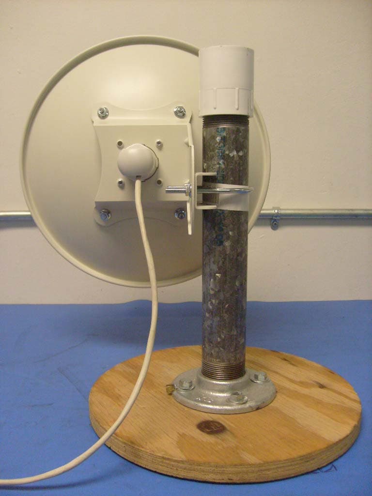
Click to zoom
Application Details
- Equipment Class
- DTS - Digital Transmission System
- Date of Grant
- Mar 22, 2012
- Application Purpose
- Original Equipment
- Date of Application
- Feb 07, 2012
- Equipment Note
- 802.11n 2x2 MIMO
- Frequency Range
- 5745.00000000 - 5825.00000000
- Company
- Ubiquiti Inc.
- Country
- United States
Documents & Files
Document Text
Text extracted from the exhibit documents filed with the FCC. Open a document above to read the original.
Users Manual
Installation Guide NanoBridge M5 Welcome Thank you for purchasing your Ubiquiti NanoBridge. This installation guide is for model NB-5G22 Tools Required for Mounting 10mm wrench (Qty. 1) Support Internet: www.ubnt.com Internet Support Forum: www.forum.ubnt.com Ubiquiti support engineers are located in the U.S. and in Europe and are dedicated to helping customers resolve software, hardware compatibility, or eld issues as quickly as possible. A D CB FGHIJ B C D E F G M6 U-Bolt M6X12 Carriage Bolt Bushing 1 4 I J 1 M6 Bolt-Springlock-Washer Assembly H 4 M6 Serrated Flange Nut 6 E A Contents Qty. Parabolic Re ector/Dish Pole Bracket Clamp 1 1 1 1 1 Dish Bracket Antenna Feed Feed Support General Warranty: UBIQUITI NETWORKS, Inc (“UBIQUITI NETWORKS”) represents and warrants that the Products furnished hereunder shall be free from defects in material and workmanship for a period of one (1) year from the date of shipment by UBIQUITI NETWORKS under normal use and operation. UBIQUITI NETWORKS sole and exclusive obligation under the foregoing warranty shall be to repair or replace, at its option, any defective Product that fails during the warranty period. The expense of removal and reinstallation of any item is not included in this warranty. and performance of the Products. UBIQUITI NETWORKS reserves the right to inspect all defective Products (which must be returned by Buyer to UBIQUITI NETWORKS factory freight prepaid). No Products will be accepted for replacement or repair without obtaining a Return Materials Authorization (RMA) number from UBIQUITI NETWORKS. Products returned without an RMA number will not be processed and will be returned to Buyer freight collect. UBIQUITI NETWORKS shall have no obligation to make repairs or replacement necessitated by catastrophe, fault, negligence, misuse, abuse, or accident by Buyer, Buyer’s customers or any other parties. The warranty period of any repaired or replaced. Product shall not extend beyond its original term. Warranty Conditions The foregoing warranty shall apply only if: (I) The Product has not been subjected to misuse, neglect or unusual physical, electrical or electromagnetic stress, or some other type of accident. (II) No modi cation, alteration or addition has been made to the Product by persons other than UBIQUITI NETWORKS or UBIQUITI NETWORKS’s authorized representatives or otherwise approved by UBIQUITI NETWORKS. (III) The Product has been properly installed and used at all times in accordance, and in all material respects, with the applicable Product documentation. Disclaimer. UBIQUITI NETWORKS does not warrant that the operation of the products is error -fr ee or that operation will be uninterrupted. In no event shall UBIQUITI NETWORKS be responsible for damages or claims of any nature or description relating to system performance, including coverage, buyer’s selection of products for buyer’s application and/or failure of products to meet government or regulatory requirements. Returns In the unlikely event a defect occurs in this product, please work through the dealer or distributor from which this product was purchased. * Products may be different from pictures and are subject to change without prior notice 6. Attach Antenna to Mounting Pole 6 5 5. Install Bushing to Feed Support 2 1. Install Feed Support to Dish Bracket Install Feed Support to Dish Bracket by: M6 Bolt-Springlock-Washer Assembly (Qty. 4) Route network cable through the bottom hole of the Feed Support and attach to the RJ-45 slot on the back of the Antenna Feed. Insert Antenna Feed into Feed Support as the orientation shown in the picture. Mounting bracket can accommodate 1.25"-2.2" pole. Attach antenna assembly to pole by: M6 U-Bolt (Qty. 1) Pole Bracket Clamp (Qty. 1) M6 Serrated Flange Nut (Qty. 2) Wrap network cable with the Bushing and then slide it into the hole in the Feed Support. C Install Dish Bracket to Dish by: M6X12 Carriage Bolt (Qty. 4) M6 Serrated Flange Nut (Qty. 4) D C B C C J B A D 2. Install Dish Bracket to Dish 1 3.Connect Network Cable to Antenna Feed 3 H G I F E I 4 4. Install Antenna Feed CH D D I G A B B JC C C FEI
Users Manual
NanoBridge 1 Typical Deployment Typical Deployment LAN or Computer to Ethernet Port labeled LAN on PoE Adapter Ethernet Port on Ubiquiti Device to Ethernet Port labeled POE on PoE Adapter Connect the Power Cord to the PoE Adapter and a power outlet Note: Shielded Category 5 (or above) cabling should be used for all wired Ethernet connections and should be grounded through the AC ground of the PoE. 2 Quick Reference Guide Application Examples AirGrid/NanoBridge mounted outdoors without the grid or dish installed provides outdoor to indoor coverage using the 3dBi feed antenna only. AirGrid/NanoBridge mounted outdoors with the grid or dish refelector installed provides directional outdoor coverage (gain reflector dependent) 3 NanoBridge Installation NanoBridge Installation These instructions cover the NanoBridge M, NB-2G18 and NB5G25. Package Contents Parabolic Reflector/DishAntenna FeedFeed SupportDish Bracket Pole Bracket Clamp M6 U-Bolt (Qty. 2) M6x12 Carriage Bolt (Qty. 4) M6 Serrated Flange Nut (Qty. 6) Feed Support Bushing M6 Bolt Spring Lock Washer Assembly (Qty. 4) * Products may be different from pictures and are subject to change without notice. Installation Requirements • 10 mm wrench Installation 1. Install the Feed Support into the Dish Bracket using four M6 Bolt-Springlock-Washer Assemblies. 4 Quick Reference Guide 2. Install the Dish Bracket to the Dish using four M6x12 Carriage Bolts and four M6 Serrated Flange Nuts. 3. Route the Ethernet cable through the bottom hole of the Feed Support and connect it to the Ethernet port on the back of the Antenna Feed. 4. Insert the Antenna Feed into the Feed Support with the orientation as shown in the image below. 5 NanoBridge Installation 5. Wrap the Feed Support Bushing around the Ethernet cable and then push it into place in the Feed Support. 6. Attach the Antenna to the pole using the two M6 U-Bolts, the two Pole Bracket Clamps, and four M6 Serrated Flange Nuts. The mounting bracket can accomodate Ø 1.25" - 2.2" pole. 6 Quick Reference Guide Accessing AirOS Connect to the airOS Configuration Interface. 1. Make sure that your host machine is connected to the LAN that is connected to the <Product Name>. 2. Configure the Ethernet adapter on your host system with a static IP address on the 192.168.1.x subnet (e.g., 192.168.1.100). 3. Launch your Web browser. Type http://192.168.1.20 in the address field and press enter (PC) or return (Mac). 4. The login screen will appear. Enter ubnt in the Username and Password fields. Select your Country and Language. You must agree to the Terms of Use to use the product. Click Login. Note: U.S. product versions are locked to the U.S. Country Code to ensure compliance with FCC regulations. The AirOS Interface will appear allowing you to customize your settings as needed. 7 Ubiquiti Networks Wiki and Forum Ubiquiti Networks Wiki and Forum Ubiquiti Networks has an online Wiki with Manuals, Guides, and Information. It is located at www.ubnt.com/wiki. Another great resource is the Ubiquiti Networks Forum. You can post and view comments, questions, and answers with other forum members and Ubiquiti staff at www.ubnt.com/forum. 8 Quick Reference Guide Installer Compliance Responsibility Devices must be professionally installed and it is the professional installer's responsibility to make sure the device is operated within local country regulatory requirements. Since Ubiquiti Networks equipment can be paired with a variety of antennas and cables, the Antenna Gain, Cable Loss, and Output Power fields are provided to the professional installer to assist in meeting regulatory requirements. 9 General Warranty General Warranty UBIQUITI NETWORKS, Inc (“UBIQUITI NETWORKS”) represents and warrants that the Products furnished hereunder shall be free from defects in material and workmanship for a period of one (1) year from the date of shipment by UBIQUITI NETWORKS under normal use and operation. UBIQUITI NETWORKS sole and exclusive obligation under the foregoing warranty shall be to repair or replace, at its option, any defective Product that fails during the warranty period. The expense of removal and reinstallation of any item is not included in this warranty. The foregoing warranty is exclusive and in lieu of all other warranties, express or implied, including the implied warranties of merchantability and fitness for a particular purpose and any warranties arising from a course of dealing, usage or trade practice with respect to the products. Repair or replacement in the manner provided herein shall be the sole and exclusive remedy of Buyer for breach of warranty and shall constitute fulfillment of all liabilities of UBIQUITI NETWORKS with respect to the quality and performance of the Products. UBIQUITI NETWORKS reserves the right to inspect all defective Products (which must be returned by Buyer to UBIQUITI NETWORKS factory freight prepaid). No Products will be accepted for replacement or repair without obtaining a Return Materials Authorization (RMA) number from UBIQUITI NETWORKS. Products returned without an RMA number will not be processed and will be returned to Buyer freight collect. UBIQUITI NETWORKS shall have no obligation to make repairs or replacement necessitated by catastrophe, fault, negligence, misuse, abuse, or accident by Buyer, Buyer’s customers or any other parties. The warranty period of any repaired or replaced. Product shall not extend beyond its original term. Warranty Conditions The foregoing warranty shall apply only if: (I) The Product has not been subjected to misuse, neglect or unusual physical, electrical or electromagnetic stress, or some other type of accident. (II) No modification, alteration or addition has been made to the Product by persons other than UBIQUITI NETWORKS or UBIQUITI NETWORK’S authorized representatives or otherwise approved by UBIQUITI NETWORKS. (III) The Product has been properly installed and used at all times in accordance, and in all material respects, with the …
Text truncated - open the document above for the full version.
Users Manual
NanoBridge 1 Typical Deployment Typical Deployment LAN or Computer to Ethernet Port labeled LAN on PoE Adapter Ethernet Port on Ubiquiti Device to Ethernet Port labeled POE on PoE Adapter Connect the Power Cord to the PoE Adapter and a power outlet Note: Shielded Category 5 (or above) cabling should be used for all wired Ethernet connections and should be grounded through the AC ground of the PoE. 2 Quick Reference Guide Application Examples AirGrid/NanoBridge mounted outdoors without the grid or dish installed provides outdoor to indoor coverage using the 3dBi feed antenna only. AirGrid/NanoBridge mounted outdoors with the grid or dish refelector installed provides directional outdoor coverage (gain reflector dependent) 3 NanoBridge Installation NanoBridge Installation These instructions cover the NanoBridge M, NB-2G18 and NB5G25. Package Contents Parabolic Reflector/DishAntenna FeedFeed SupportDish Bracket Pole Bracket Clamp M6 U-Bolt (Qty. 2) M6x12 Carriage Bolt (Qty. 4) M6 Serrated Flange Nut (Qty. 6) Feed Support Bushing M6 Bolt Spring Lock Washer Assembly (Qty. 4) * Products may be different from pictures and are subject to change without notice. Installation Requirements • 10 mm wrench Installation 1. Install the Feed Support into the Dish Bracket using four M6 Bolt-Springlock-Washer Assemblies. 4 Quick Reference Guide 2. Install the Dish Bracket to the Dish using four M6x12 Carriage Bolts and four M6 Serrated Flange Nuts. 3. Route the Ethernet cable through the bottom hole of the Feed Support and connect it to the Ethernet port on the back of the Antenna Feed. 4. Insert the Antenna Feed into the Feed Support with the orientation as shown in the image below. 5 NanoBridge Installation 5. Wrap the Feed Support Bushing around the Ethernet cable and then push it into place in the Feed Support. 6. Attach the Antenna to the pole using the two M6 U-Bolts, the two Pole Bracket Clamps, and four M6 Serrated Flange Nuts. The mounting bracket can accomodate Ø 1.25" - 2.2" pole. 6 Quick Reference Guide Accessing AirOS Connect to the airOS Configuration Interface. 1. Make sure that your host machine is connected to the LAN that is connected to the <Product Name>. 2. Configure the Ethernet adapter on your host system with a static IP address on the 192.168.1.x subnet (e.g., 192.168.1.100). 3. Launch your Web browser. Type http://192.168.1.20 in the address field and press enter (PC) or return (Mac). 4. The login screen will appear. Enter ubnt in the Username and Password fields. Select your Country and Language. You must agree to the Terms of Use to use the product. Click Login. Note: U.S. product versions are locked to the U.S. Country Code to ensure compliance with FCC regulations. The AirOS Interface will appear allowing you to customize your settings as needed. 7 Ubiquiti Networks Wiki and Forum Ubiquiti Networks Wiki and Forum Ubiquiti Networks has an online Wiki with Manuals, Guides, and Information. It is located at www.ubnt.com/wiki. Another great resource is the Ubiquiti Networks Forum. You can post and view comments, questions, and answers with other forum members and Ubiquiti staff at www.ubnt.com/forum. 8 Quick Reference Guide Installer Compliance Responsibility Devices must be professionally installed and it is the professional installer's responsibility to make sure the device is operated within local country regulatory requirements. Since Ubiquiti Networks equipment can be paired with a variety of antennas and cables, the Antenna Gain, Cable Loss, and Output Power fields are provided to the professional installer to assist in meeting regulatory requirements. 9 General Warranty General Warranty UBIQUITI NETWORKS, Inc (“UBIQUITI NETWORKS”) represents and warrants that the Products furnished hereunder shall be free from defects in material and workmanship for a period of one (1) year from the date of shipment by UBIQUITI NETWORKS under normal use and operation. UBIQUITI NETWORKS sole and exclusive obligation under the foregoing warranty shall be to repair or replace, at its option, any defective Product that fails during the warranty period. The expense of removal and reinstallation of any item is not included in this warranty. The foregoing warranty is exclusive and in lieu of all other warranties, express or implied, including the implied warranties of merchantability and fitness for a particular purpose and any warranties arising from a course of dealing, usage or trade practice with respect to the products. Repair or replacement in the manner provided herein shall be the sole and exclusive remedy of Buyer for breach of warranty and shall constitute fulfillment of all liabilities of UBIQUITI NETWORKS with respect to the quality and performance of the Products. UBIQUITI NETWORKS reserves the right to inspect all defective Products (which must be returned by Buyer to UBIQUITI NETWORKS factory freight prepaid). No Products will be accepted for replacement or repair without obtaining a Return Materials Authorization (RMA) number from UBIQUITI NETWORKS. Products returned without an RMA number will not be processed and will be returned to Buyer freight collect. UBIQUITI NETWORKS shall have no obligation to make repairs or replacement necessitated by catastrophe, fault, negligence, misuse, abuse, or accident by Buyer, Buyer’s customers or any other parties. The warranty period of any repaired or replaced. Product shall not extend beyond its original term. Warranty Conditions The foregoing warranty shall apply only if: (I) The Product has not been subjected to misuse, neglect or unusual physical, electrical or electromagnetic stress, or some other type of accident. (II) No modification, alteration or addition has been made to the Product by persons other than UBIQUITI NETWORKS or UBIQUITI NETWORK’S authorized representatives or otherwise approved by UBIQUITI NETWORKS. (III) The Product has been properly installed and used at all times in accordance, and in all material respects, with the …
Text truncated - open the document above for the full version.
Cover Letter(s)
91 E. Tasman Dr. | San Jose, CA 95134 | U.S.A. | Tel. 1-408-942-3085| Fax 1-408-351-4973. NanoBridgeM5 DTS Report Ubiquiti Networks is requesting the FCC to accept the FCC 15.247 DTS Report for the NanoBridgeM5 (M5D), FCC ID: SWX-M5D for the new composite application for the NanoBridgeM5, FCC ID: SWX-NBM5D. The only difference between FCC ID: SWX-M5D and FCC ID: SWX-NBM5D is model name/ID and software.
RF Exposure Info
Antenna M5D Ubiquiti D-5G-25 25dBi 5GHz 400mm Diameter
Test Report
MET Laboratories, Inc. Safety Certification - EMI - Telecom Environmental Simulation 914 WEST PATAPSCO AVENUE ! BALTIMORE, MARYLAND 21230-3432 ! PHONE (410) 354-3300 ! FAX (410) 354-3313 33439 WESTERN AVENUE ● UNION CITY, CALIFORNIA 94587 ● PHONE (510) 489-6300 ● FAX (510) 489-6372 3162 BELICK STREET ● SANTA CLARA, CALIFORNIA 95054 ● PHONE (408 748-3585 ● FAX (510) 489-6372 The Nation’s First Licensed Nationally Recognized Testing Laboratory July 15, 2010 Ubiquiti Networks 91 E. Tasman San Jose, CA 95134 Dear Robert Pera, Enclosed is the EMC Wireless test report for compliance testing of the Ubiquiti Networks, M5D as tested to the requirements of Title 47 of the CFR, Ch. 1 (10-1-06 ed.), Part 15, Subpart B, ICES-003, Issue 4 February 2004 for a Class A Digital Device and FCC Part 15 Subpart C, RSS-210, Issue 7, June 2007 for Intentional Radiators. Thank you for using the services of MET Laboratories, Inc. If you have any questions regarding these results or if MET can be of further service to you, please feel free to contact me. Sincerely yours, MET LABORATORIES, INC. Jennifer Warnell Documentation Department Reference: (\Ubiquiti Networks\EMCS82082B-FCC247 Rev. 1) Certificates and reports shall not be reproduced except in full, without the written permission of MET Laboratories, Inc. Electromagnetic Compatibility Ubiquiti Networks Cover Page M5D CFR Title 47, Part 15B, 15.247; RSS-210, Issue 7, June 2007 & ICES-003 MET Report: EMCS82082B-FCC247 Rev. 1 © 2010, MET Laboratories, Inc. Page ii of x DOC-EMC702 2/18/2010 Electromagnetic Compatibility Criteria Test Report for the Ubiquiti Networks M5D Tested under the FCC Certification Rules contained in Title 47 of the CFR, Parts 15 Subpart B & ICES-003 for Class A Digital Devices & 15.247 Subpart C & RSS-210, Issue 7, June 2007 for Intentional Radiators MET Report: EMCS82082B-FCC247 Rev. 1 July 15, 2010 Prepared For: Ubiquiti Networks 91 E. Tasman San Jose, CA 95134 Prepared By: MET Laboratories, Inc. 3162 Belick St. Santa Clara, CA 95054 Electromagnetic Compatibility Ubiquiti Networks Cover Page M5D CFR Title 47, Part 15B, 15.247; RSS-210, Issue 7, June 2007 & ICES-003 MET Report: EMCS82082B-FCC247 Rev. 1 © 2010, MET Laboratories, Inc. Page iii of x DOC-EMC702 2/18/2010 Electromagnetic Compatibility Criteria Test Report for the Ubiquiti Networks M5D Tested under the FCC Certification Rules contained in Title 47 of the CFR, Parts 15 Subpart B & ICES-003 for Class A Digital Devices & 15.247 Subpart C & RSS-210, Issue 7, June 2007 for Intentional Radiators Minh Ly, Project Engineer Jennifer Warnell Electromagnetic Compatibility Lab Documentation Department Engineering Statement: The measurements shown in this report were made in accordance with the procedures indicated, and the emissions from this equipment were found to be within the limits applicable. I assume full responsibility for the accuracy and completeness of these measurements, and for the qualifications of all persons taking them. It is further stated that upon the basis of the measurements made, the equipment tested is capable of operation in accordance with the requirements of the FCC Rules Parts 15B, 15.247 and Industry Canada standards ICES-003, Issue 4 February 2004, RSS-210, Issue 7, June 2007 under normal use and maintenance. Shawn McMillen, Wireless Manager, Electromagnetic Compatibility Lab Electromagnetic Compatibility Ubiquiti Networks Report Status M5D CFR Title 47, Part 15B, 15.247; RSS-210, Issue 7, June 2007 & ICES-003 MET Report: EMCS82082B-FCC247 Rev. 1 © 2010, MET Laboratories, Inc. Page iv of x DOC-EMC702 2/18/2010 Report Status Sheet Revision Report Date Reason for Revision June 21, 2010 Initial Issue. 1 July 15, 2010 Revised to reflect correct antenna gain. Electromagnetic Compatibility Ubiquiti Networks Table of Contents M5D CFR Title 47, Part 15B, 15.247; RSS-210, Issue 7, June 2007 & ICES-003 MET Report: EMCS82082B-FCC247 Rev. 1 © 2010, MET Laboratories, Inc. Page v of x DOC-EMC702 2/18/2010 Table of Contents I. Executive Summary .................................................................................................................................................1 A. Purpose of Test ...................................................................................................................................................2 B. Executive Summary ............................................................................................................................................2 II. Equipment Configuration .......................................................................................................................................3 A. Overview.............................................................................................................................................................4 B. References...........................................................................................................................................................5 C. Test Site ..............................................................................................................................................................5 D. Description of Test Sample.................................................................................................................................6 E. Equipment Configuration....................................................................................................................................8 F. Support Equipment .............................................................................................................................................8 G. Ports and Cabling Information ............................................................................................................................8 H. Mode of Operation..............................................................................................................................................9 I.…
Text truncated - open the document above for the full version.
Contact Information
Applicant
Alex Macon
Technical Contact
Ubiquiti NetworksJennifer Sanchez
[email protected]408-942-3085
91 E. Tasman Drive · San Jose, California · United States
Test Firm
Element Materials Technology Fremont NewarkDavid Bare
Technical Specifications
| # | Rule Parts | Frequency Range | Power Output | Tolerance |
|---|---|---|---|---|
| 2 | 15C | 5.75 GHz - 5.83 GHz | 444.00 mW | % |
Other Applications from Ubiquiti Inc.
SWX-USLGGH
Aug 20, 2026SuperLink Gateway HA
Equipment Class
DTS - Digital Transmission SystemSWX-UTRLR
Aug 19, 2026Digital Transmission Radio
Equipment Class
DTS - Digital Transmission SystemSWX-USLER
Aug 12, 2026Recessed Entry Sensor
Equipment Class
DSS - Part 15 Spread Spectrum TransmitterSWX-UVCG6ED
Jul 07, 2026G6 Edge Dome
Equipment Class
DTS - Digital Transmission SystemSWX-UVCG6ET
Jul 07, 2026G6 Edge Turret
Equipment Class
DTS - Digital Transmission System