SWX-UVPPROVOIP PHONE
Ubiquiti Inc.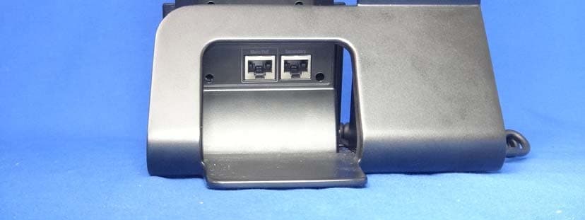
Click to zoom
Application Details
- Equipment Class
- DTS - Digital Transmission System
- Date of Grant
- Dec 01, 2014
- Application Purpose
- Original Equipment
- Date of Application
- Dec 01, 2014
- Equipment Note
- VOIP PHONE
- Frequency Range
- 2402.00000000 - 2480.00000000
- Company
- Ubiquiti Inc.
- Country
- United States
Documents & Files
Document Text
Text extracted from the exhibit documents filed with the FCC. Open a document above to read the original.
Users Manual
Enterprise VoIP Phone with 5" Touchscreen, Bluetooth, WiFi, and Built-In Camera Model: UVP-Pro Calculator Calculator Calendar Calendar Gallery Gallery Sound Recorder Sound Recorder Hangouts Hangouts Gmail Gmail Settings Settings Drive Drive Introduction Thank you for purchasing the Ubiquiti Networks ® UniFi ® VoIP Phone Professional, model UVP-Pro. The UniFi VoIP Phone Professional is designed to integrate easily into a UniFi network. The phone interface is based on the popular Android ™ platform for ease of use. This Quick Start Guide is designed to guide you through the installation, provide an overview of the interface, and also includes the warranty terms. Package Contents Enterprise VoIP Phone with 5" Touchscreen, WiFi, and Built-In Camera Model: UVP-Pro C al c ul ato r C a lcula tor C al en d ar C al e nd ar Ga ll e ry G al lery Sound R ec o rde r Soun d R ec o rde r Ha n g o ut s H an g ou t s Gmail Gmail S e t t ings Set t ings D riv e D riv e UniFi VoIP Phone ProfessionalQuick Start Guide Installation Requirements • UniFi Security Gateway • UniFi Switch or PoE+ (802.3at-compliant) switch • UniFi Controller TERMS OF USE: All Ethernet cabling runs must use CAT5 (or above). It is the customer’s responsibility to follow local country regulations and indoor cabling requirements. Before You Begin Remove the protective covering from the handset. Remove the protective film from the touchscreen. Hardware Overview Front Camera LED Touchscreen Camera Built-in camera can be used for snapping photos for avatars or videoconferencing applications. Touchscreen The 5" (diagonal) touchscreen display is used for all interface navigation and dialing. LED The LED will illuminate when the device is first connected to a 48V power source. Once the phone has started up, the LED will turn off. IMPORTANT: The LED will flash when a firmware update is occurring. Do not disconnect power/Ethernet from the device during this time. Back Ports Main/PoESecondary Main/PoE Secondary Main/PoE The Main/PoE Ethernet port is 802.3at-compliant and is used to connect data and power to the UniFi VoIP Phone Pro. Connect this port to the same network as the UniFi Security Gateway VOIP port. Secondary The Secondary Ethernet port is used for bridging. WARNING: Do not connect a powered Ethernet connection to the Secondary port. Side Ports Micro-USB Port The Micro-USB port is only intended for advanced users connecting the UniFi VoIP Phone Pro to a computer. Headset Jack 3.5 mm jack for optional wired stereo and microphone headsets. Handset Mute button Mute Press the Mute button to mute the microphone on the handset. *640-00143-03* 640-00143-03 Hardware Installation The UniFi VoIP Phone Professional is designed for desktop placement. To connect the phone, perform the following steps: 1. Connect one end of an Ethernet cable to the wall jack that is connected to your 48V, 802.3at-compliant switch. 2. Connect the other end of the Ethernet cable to the port labeled Main/PoE on the UniFi VoIP Phone Professional. Main/PoESecondary Software Configuration The UniFi VoIP Phone Professional is automatically detected by the UniFi Controller (4.6.x or above). Installing the UniFi Controller If you haven’t already installed the UniFi Controller software, you can download it at downloads.ubnt.com/unifi Adopting the Phone in the UniFi Controller 1. Launch the UniFi Controller and go to the Devices tab. 2. Click Adopt. Navigating the Interface The Home screen contains a Google ™ search bar, five default icons at the bottom of the screen, and the three action bar icons. Google Search Bar Use the Google search bar to type or speak voice commands. Touch the bar to bring up a virtual keyboard, or touch the microphone icon to say a voice command. Default Home Screen Icons IconDescription Phone Displays the keypad to make a call. Recent calls, contacts, and voicemail are also accessible from here. Camera Press to access the camera. Apps Press to access the Apps screen. This default icon is the only one that cannot be removed from the Home screen. Google Play ™ Store Press to open the Google Play Store. Download apps, music, movies, books, games, and other media. A new or existing account is required for access. Google Apps Folder Contains the Google suite of apps including Gmail ™ , YouTube ™ , Google Chrome ™ , Hangouts ™ , Google Drive ™ , Google Maps ™ , and more. Action Bar Icons IconDescription Back Opens the previous screen you were working in, even if it was in a different app. Once you return to the Home screen, you can’t go back any further. Home Returns to the Home screen. Recent Apps Displays a list of recently used apps. Press an app to open it. To close an app and remove it from the list, swipe it left or right. Customizing the Home Screen Widgets and shortcuts to favorite apps can be placed on the Home screen. Multiple app shortcuts can also be grouped into one folder. Adding App Shortcuts to the Home Screen To place an app on the Home screen, press the Apps icon on the Home screen. The Apps screen will be displayed. Press and hold the icon until it appears on the Home screen. Drag the icon to the desired location and release it. Creating Folders on the Home Screen To create a folder containing multiple app shortcuts, drag an app shortcut over another app shortcut on the Home screen. Removing Items from the Home Screen To remove a widget or app shortcut from the Home screen, press and hold the item until the Remove text appears at the top of the screen. Drag the item to the Remove text. Making a Call Lift the handset to make a call and the dialer screen will appear. Use the touchscreen to enter the phone number. Use the Delete button to correct any mistakes. Press the Call button to make a call. JKLGHI ABCDEF MNO TUVPQRSWXYZ KEYPAD CONTACTS 231 564 8 0 97 Call Delete Contacts Call Call Manager Volume Slider Connected Number Connection Status Connected Number Displays the extension or phone number that is being dialed or that is current…
Text truncated - open the document above for the full version.
Cover Letter(s)
SCS-F18: Project and Product Certification Representative Authorization Letter Page 1 of 2 Rev 3.0 775 Montague Expressway Milpitas, CA 95035 Tel: 408-526-1188 Fax: 408-526-1088 Email: [email protected] Project and Product Certification Representative Authorization Letter Reason for Amendment (current / obsolete) Revision History Approved Date From To Initial Release (obsolete) 1.0 1.0 Nov-14-2006 Revised wording (obsolete) 1.0 2.0 Sept–25-2007 Updated company template (current) 2.0 3.0 Jan-31-2012 SCS-F18: Project and Product Certification Representative Authorization Letter Page 2 of 2 Rev 3.0 2014-10-11 To: SIEMIC, INC. 775 Montague Expressway, Milpitas, CA 95035 USA Dear Sir/Madam, Re: Project and Product Certification Representative Authorization Letter We, _____ Ubiquiti Networks, Inc _____hereby authorize SIEMIC, INC. to act as a Certification Body for certifying for the following project(s): (Product description: VOIP PHONE Model name: UVP-Pro FCC ID: SWX-UVPPRO Sincerely, Signature : Name and Job Title. : Ted Hsiao E-mail : [email protected] Tel. : (886)2-2758-1657 x144/107
Cover Letter(s)
775 Montague Expressway Milpitas, CA 95035 Tel: 408-526-1188 Fax: 408-526-1088 Email: [email protected] Confidentiality Request Letter Reason for Amendment (current / obsolete) Revision History Approved Date From To Initial Release (obsolete) 1.0 1.0 Nov-14-2006 Adding CFR 2.459 (obsolete) 1.0 2.0 August – 11 - 2008 Updated company template & Added text box (current) 2.0 3.0 Jan-31-2012 SCS-F19: Confidentiality Request Letter Page 1 of 3 Rev 3.0 2014-10-11 To: Federal Communications Commission Authorization and Evaluation Division 7435 Oakland Mills Road Columbia, MD Subject: Permanent Confidentiality Request for FCC ID: SWX-UVPPRO We hereby request confidential treatment of information accompanying this application as outlined below: - e.g. security form - e.g. Schematic - e.g. Block diagram - e.g. Operational description The above materials contain trade secrets and proprietary information not customarily released to the public. The public disclosure of these materials may be harmful to the applicant and provide unjustified benefits to its competitors. The applicant understands that pursuant to Section 0.457 & 0.459 of the Rules, disclosure of this application and all accompanying documentation will not be made before the date of the Grant for this application. Sincerely, Signature : Name and Job Title. : Ted Hsiao E-mail : [email protected] Tel. : (886)2-2758-1657 x144/107 SCS-F19: Confidentiality Request Letter Page 2 of 3 Rev 3.0 To: Federal Communications Commission Communications Commission Office of Engineering and Technology Equipment Authorization Division 7345 Oakland Mills Road Columbia, Maryland 21046 Subject: Short Term Confidentiality Request for FCC ID: SWX-UVPPRO To Whom It May Concern: Pursuant to sections 0.457 and 0.459 of CFR 47 and to avoid premature release of sensitive information prior to marketing or release of the product to the public, the applicant requests the following documents contained in this certification application be temporarily withheld from public disclosure for an initial period of 45 or 180 days (please check one). - User Manual - User Manual Insert - Internal Photo - External Photo - Test Setup Photo The above materials contain trade secrets and proprietary information not customarily released to the public. The public disclosure of these materials may be harmful to the applicant and provide unjustified benefits to its competitors. Sincerely, Signature : Signature : Name and Job Title. : Ted Hsiao E-mail : [email protected] Tel. : (886)2-2758-1657 x144/107 SCS-F19: Confidentiality Request Letter Page 3 of 3 Rev 3.0
Cover Letter(s)
Ubiquiti Networks 12F, No. 105, Song Ren Rd., Sin Yi District, Taipei 110, Taiwan Telephone: (886)2-2758-1657 Fax No.: (886)2-2758-1637 DTS‐UNII Device Declaration Letter To whom it may concern: We have declared below featured for FCC equipment authorization, Device FCC ID : SWX‐UVPPRO, IC: 6545A‐UVPPRO (1) DFS Device -- Master , Client with Radar detection capability , Client without radar detection capability , N/A (2) Active / Passive Scanning , adhoc mode access point capability Frequency Band (MHz) Active Scanning (the device can transmit a probe (beacon)) passive scanning (where the device is can listen only with no probes) Ad Hoc Mode or WIFI Direct capability Access point capability 5745-5825 Yes , No Yes , No Yes , No Yes , No 5755-5795 Yes , No Yes , No Yes , No Yes , No 5180-5240 Yes , No Yes , No Yes , No Yes , No 5260-5320 Yes , No Yes , No Yes , No Yes , No 5500-5700 Yes , No Yes , No Yes , No Yes , No 5190-5230 Yes , No Yes , No Yes , No Yes , No 5270-5310 Yes , No Yes , No Yes , No Yes , No 5510-5670 Yes , No Yes , No Yes , No Yes , No This information when programmed into the EEPROM will not be accessible and can not be changed by the end user. If you have any questions please do not hesitate to contact us. Signature, ‐‐‐‐‐‐‐‐‐‐‐‐‐‐‐‐‐‐‐‐‐‐‐‐‐‐‐‐‐‐‐‐‐‐‐‐‐‐‐‐‐‐‐‐‐‐‐‐‐‐‐‐‐‐‐‐‐‐‐‐‐‐‐‐‐‐‐‐‐‐‐‐‐‐‐‐‐‐‐‐‐‐‐‐‐‐‐‐‐‐‐‐‐‐‐‐‐‐‐‐‐‐‐‐‐‐ Ted Hsiao / Manager Ubiquiti Networks Telephone: (886)2-2758-1657 Fax No.: (886)2-2758-1637 Email: [email protected]
External Photos
Report No.: 1490232R-RFUSP26V00 Page : 1 of 18 Attachment 2 : EUT Detailed Photographs (1) EUT Photo (2) EUT Photo Report No.: 1490232R-RFUSP26V00 Page : 2 of 18 (3) EUT Photo (4) EUT Photo
ID Label/Location Info
Lab Lab el location a el location a and format at EUT of bottom sid de.
Internal Photos
Report No.: 1490232R-RFUSP26V00 Page : 3 of 18 (5) EUT Photo (6) EUT Photo Report No.: 1490232R-RFUSP26V00 Page : 4 of 18 (7) EUT Photo (8) EUT Photo Report No.: 1490232R-RFUSP26V00 Page : 5 of 18 (9) EUT Photo (10) EUT Photo Report No.: 1490232R-RFUSP26V00 Page : 6 of 18 (11) EUT Photo (12) EUT Photo Antenna WLAN+Bluetooth Chip IC Report No.: 1490232R-RFUSP26V00 Page : 7 of 18 (13) EUT Photo (14) EUT Photo Report No.: 1490232R-RFUSP26V00 Page : 8 of 18 (15) EUT Photo (16) EUT Photo Report No.: 1490232R-RFUSP26V00 Page : 9 of 18 (17) EUT Photo (18) EUT Photo Report No.: 1490232R-RFUSP26V00 Page : 10 of 18 (19) EUT Photo (20) EUT Photo Report No.: 1490232R-RFUSP26V00 Page : 11 of 18 (21) EUT Photo (22) EUT Photo Report No.: 1490232R-RFUSP26V00 Page : 12 of 18 (23) EUT Photo (24) EUT Photo Report No.: 1490232R-RFUSP26V00 Page : 13 of 18 (25) EUT Photo (26) EUT Photo Report No.: 1490232R-RFUSP26V00 Page : 14 of 18 (27) EUT Photo (28) EUT Photo Report No.: 1490232R-RFUSP26V00 Page : 15 of 18 (29) EUT Photo (30) EUT Photo Report No.: 1490232R-RFUSP26V00 Page : 16 of 18 (31) EUT Photo (32) EUT Photo Report No.: 1490232R-RFUSP26V00 Page : 17 of 18 (33) EUT Photo (34) EUT Photo Report No.: 1490232R-RFUSP26V00 Page : 18 of 18 (35) EUT Photo
RF Exposure Info
Report No.: 1490232R-RFUSP26V00 Page: 1 of 3 RF Exposure Evaluation declaration Product Name VoIP Phone Model No. UVP-Pro FCC ID SWX-UVPPRO Applicant Ubiquiti Networks.,Inc Address 12F, No. 105, Song Ren Rd., Sin Yi District, Taipei 110, Taiwan Date of Receipt Sep. 05, 2014 Date of Declaration Nov. 14, 2014 Report No. 1490232R-RFUSP26V00 The declaration results relate only to the samples calculated. The declaration shall not be reproduced except in full without the written approval of QuieTek Corporation. This report must not be used to claim product endorsement by TAF any agency of the U.S. Government Report No.: 1490232R-RFUSP26V00 Page: 2 of 3 1. RF Exposure Evaluation 1.1. Limits According to FCC 1.1310: The criteria listed in the following table shall be used to evaluate the environment impact of human exposure to radio frequency (RF) radiation as specified in 1.1307(b) LIMITS FOR MAXIMUM PERMISSIBLE EXPOSURE (MPE) Frequency Range (MHz) Electric Field Strength (V/m) Magnetic Field Strength (A/m) Power Density (mW/cm 2 ) Average Time (Minutes) (A) Limits for Occupational/ Control Exposures 300-1500 -- -- F/300 6 1500-100,000 -- -- 5 6 (B) Limits for General Population/ Uncontrolled Exposures 300-1500 -- -- F/1500 6 1500-100,000 -- -- 1 30 F= Frequency in MHz Friis Formula Friis transmission formula: Pd = (Pout*G)/(4*pi*r 2 ) Where Pd = power density in mW/cm 2 Pout = output power to antenna in mW G = gain of antenna in linear scale Pi = 3.1416 R = distance between observation point and center of the radiator in cm Pd id the limit of MPE, 1 mW/cm 2 . If we know the maximum gain of the antenna and the total power input to the antenna, through the calculation, we will know the distance r where the MPE limit is reached. 1.2. Test Procedure Software provided by client enabled the EUT to transmit and receive data at lowest, middle and highest channel individually. The temperature and related humidity: 18and 78°C% RH. Report No.: 1490232R-RFUSP26V00 Page: 3 of 3 1.3. Test Result of RF Exposure Evaluation Product : VoIP Phone Test Item : RF Exposure Evaluation Test Site : No.3 OATS (2.4GHz) Output Power Into Antenna & RF Exposure Evaluation Distance: Target Conducted output power 21dBm Power Tolerance ±2dB Maximum Conducted output power 23dBm (note) Antenna gain 2.27dBi Note: Maximum Conducted output power = Target Conducted output power + Power Tolerance Output Power to Antenna (mW) Power Density at R = 20 cm (mW/cm2) 199.5262 0.066947 Power density is lower than the limit (1 mW/cm 2 ). (5GHz) Output Power Into Antenna & RF Exposure Evaluation Distance: Target Conducted output power 14dBm Power Tolerance ±2dB Maximum Conducted output power 16dBm (note) Antenna gain 5.18dBi Note: Maximum Conducted output power = Target Conducted output power + Power Tolerance Output Power to Antenna (mW) Power Density at R = 20 cm (mW/cm2) 39.8107 0.026105 Power density is lower than the limit (1 mW/cm 2 ). Operation Frequency Range 2412-2462MHz, 2402-2480MHz 5745-5825MHz, 5755-5795MHz 5180-5240MHz, 5190-5230MHz 5300-5700MHz, 5270-5670MHz
Test Report
Report No.: 1490232R-RFUSP73V00-A Page: 1 of 40 FCC Test Report Product Name VoIP Phone Model No. UVP-Pro FCC ID. SWX-UVPPRO Applicant Ubiquiti Networks, Inc. Address 12F, No. 105, Song Ren Rd., Sin Yi District, Taipei 110, Taiwan Date of Receipt Sep. 05, 2014 Issued Date Nov. 14, 2014 Report No. 1490232R-RFUSP73V00-A Report Version V1.0 The test results relate only to the samples tested. The test results shown in the test report are traceable to the national/international standard through the calibration report of the equipment and evaluated measurement uncertainty herein. This report must not be used to claim product endorsement by TAF or any agency of the government. The test report shall not be reproduced without the written approval of QuieTek Corporation. Report No.: 1490232R-RFUSP73V00-A Page: 2 of 40 Test Report Issued Date: Nov. 14, 2014 Report No.: 1490232R-RFUSP73V00-A Product Name VoIP Phone Applicant Ubiquiti Networks, Inc. Address 12F, No. 105, Song Ren Rd., Sin Yi District, Taipei 110, Taiwan Manufacturer Ubiquiti Networks, Inc. Model No. UVP-Pro FCC ID. SWX-UVPPRO EUT Rated Voltage DC 48V (Power by POE) EUT Test Voltage AC 120V/ 60Hz Trade Name UBIQUITI Applicable Standard FCC CFR Title 47 Part 15 Subpart C: 2014 ANSI C63.10: 2009, KDB 558074 D01 DTS Meas Guidance v03r02 Test Result Complied Documented By : ( Senior Adm. Specialist / Rita Huang ) Tested By : ( Engineer / Benjamin Pan) Approved By : ( Director / Vincent Lin ) Report No.: 1490232R-RFUSP73V00-A Page: 3 of 40 TABLE OF CONTENTS Description Page 1. GENERAL INFORMATION ...............................................................................................................4 1.1. EUT Description......................................................................................................................................4 1.2. Operational Description...........................................................................................................................6 1.3. Tested System Details..............................................................................................................................7 1.4. Configuration of Tested System ..............................................................................................................7 1.5. EUT Exercise Software ...........................................................................................................................7 1.6. Test Facility .............................................................................................................................................8 2. CONDUCTED EMISSION ..................................................................................................................9 2.1. Test Equipment ........................................................................................................................................9 2.2. Test Setup ................................................................................................................................................9 2.3. Limits.....................................................................................................................................................10 2.4. Test Procedure .......................................................................................................................................10 2.5. Uncertainty ............................................................................................................................................10 2.6. Test Result of Conducted Emission .......................................................................................................11 3. PEAK POWER OUTPUT ..................................................................................................................13 3.1. Test Equipment ......................................................................................................................................13 3.2. Test Setup ..............................................................................................................................................13 3.3. Limit .....................................................................................................................................................13 3.4. Test Procedure .......................................................................................................................................13 3.5. Uncertainty ............................................................................................................................................13 3.6. Test Result of Peak Power Output .........................................................................................................14 4. RADIATED EMISSION .....................................................................................................................15 4.1. Test Equipment ......................................................................................................................................15 4.2. Test Setup ..............................................................................................................................................15 4.3. Limits.....................................................................................................................................................16 4.4. Test Procedure .......................................................................................................................................17 4.5. Uncertainty ............................................................................................................................................17 4.6. Test Result of Radiated Emission ..........................................................................................................18 5. RF ANTENNA CONDUCTED TEST................................................................................................22 5.1. Test …
Text truncated - open the document above for the full version.
Test Report
Report No.: 1490232R-RFUSP26V00 Page : 1 of 93 FCC Test Report Product Name VoIP Phone Model No UVP-Pro FCC ID. SWX-UVPPRO Applicant Ubiquiti Networks, Inc. Address 12F, No. 105, Song Ren Rd., Sin Yi District, Taipei 110, Taiwan Date of Receipt Sep. 05, 2014 Issue Date Nov. 14, 2014 Report No. 1490232R-RFUSP26V00 Report Version V1.0 The test results relate only to the samples tested. The test results shown in the test report are traceable to the national/international standard through the calibration report of the equipment and evaluated measurement uncertainty herein. This report must not be used to claim product endorsement by TAF or any agency of the government. The test report shall not be reproduced without the written approval of QuieTek Corporation. Report No.: 1490232R-RFUSP26V00 Page : 2 of 93 Test Report Issue Date: Nov. 14, 2014 Report No.: 1490232R-RFUSP26V00 Product Name VoIP Phone Applicant Ubiquiti Networks, Inc. Address 12F, No. 105, Song Ren Rd., Sin Yi District, Taipei 110, Taiwan Manufacturer Ubiquiti Networks, Inc. Model No. UVP-Pro FCC ID. SWX-UVPPRO EUT Rated Voltage DC 48V (Power by POE) EUT Test Voltage AC 120V/60Hz Trade Name UBIQUITI Applicable Standard FCC CFR Title 47 Part 15 Subpart C: 2014 ANSI C63.10: 2009, KDB 558074 D01 DTS Meas Guidance v03r02 Test Result Complied Documented By : ( Senior Adm. Specialist / Rita Huang ) Tested By : ( Engineer / Benjamin Pan) Approved By : ( Director / Vincent Lin ) Report No.: 1490232R-RFUSP26V00 Page : 3 of 93 TABLE OF CONTENTS Description Page 1. GENERAL INFORMATION .....................................................................................................5 1.1. EUT Description............................................................................................................................5 1.2. Operational Description ................................................................................................................7 1.3. Tested System Details....................................................................................................................8 1.4. Configuration of Tested System ....................................................................................................8 1.5. EUT Exercise Software .................................................................................................................8 1.6. Test Facility ...................................................................................................................................9 2. Conducted Emission..................................................................................................................10 2.1. Test Equipment............................................................................................................................10 2.2. Test Setup ....................................................................................................................................10 2.3. Limits ..........................................................................................................................................11 2.4. Test Procedure .............................................................................................................................11 2.5. Uncertainty ..................................................................................................................................11 2.6. Test Result of Conducted Emission.............................................................................................12 3. Maximum Conducted Power....................................................................................................14 3.1. Test Equipment............................................................................................................................14 3.2. Test Setup ....................................................................................................................................14 3.3. Limits ..........................................................................................................................................14 3.4. Test Procedure .............................................................................................................................14 3.5. Uncertainty ..................................................................................................................................14 3.6. Test Result of Peak Power Output...............................................................................................15 4. Radiated Emission .....................................................................................................................19 4.1. Test Equipment............................................................................................................................19 4.2. Test Setup ....................................................................................................................................20 4.3. Limits ..........................................................................................................................................21 4.4. Test Procedure .............................................................................................................................22 4.5. Uncertainty ..................................................................................................................................22 4.6. Test Result of Radiated Emission................................................................................................23 5. RF antenna conducted test........................................................................................................39 5.1. Test Equipment............................................................................................................................39 5.2. Test Setup ......................................................................................................................…
Text truncated - open the document above for the full version.
Test Setup Photos
Report No.: 1490232R-RFUSP26V00 Page : 1 of 3 Attachment 1: EUT Test Setup Photographs Front View of Conducted Test Back View of Conducted Test Report No.: 1490232R-RFUSP26V00 Page : 2 of 3 Front View of Radiated Test Back View of Radiated Test Report No.: 1490232R-RFUSP26V00 Page : 3 of 3 Front View of Radiated Test (Horn) Back View of Radiated Test (Horn)
Contact Information
Applicant
Alex Macon
Test Firm
DEKRA TESTING AND CERTIFICATION CO., LTD. LinKouMirenda Liao
Technical Specifications
| # | Rule Parts | Frequency Range | Power Output |
|---|---|---|---|
| 2 | 15C | 2.40 GHz - 2.48 GHz | 1.30 mW |
Other Applications from Ubiquiti Inc.
SWX-USLGGH
Aug 20, 2026SuperLink Gateway HA
Equipment Class
DTS - Digital Transmission SystemSWX-UTRLR
Aug 19, 2026Digital Transmission Radio
Equipment Class
DTS - Digital Transmission SystemSWX-USLER
Aug 12, 2026Recessed Entry Sensor
Equipment Class
DSS - Part 15 Spread Spectrum TransmitterSWX-UVCG6ED
Jul 07, 2026G6 Edge Dome
Equipment Class
DTS - Digital Transmission SystemSWX-UVCG6ET
Jul 07, 2026G6 Edge Turret
Equipment Class
DTS - Digital Transmission System