SWX-WAVEAMDigital Transmission Radio
Ubiquiti Inc.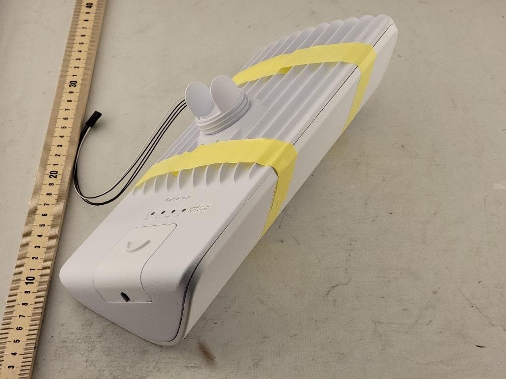
Click to zoom
Application Details
- Equipment Class
- DTS - Digital Transmission System
- Date of Grant
- Nov 10, 2022
- Application Purpose
- Original Equipment
- Date of Application
- Nov 10, 2022
- Equipment Note
- Digital Transmission Radio
- Frequency Range
- 2402.00000000 - 2480.00000000
- Company
- Ubiquiti Inc.
- Country
- United States
Documents & Files
Document Text
Text extracted from the exhibit documents filed with the FCC. Open a document above to read the original.
Users Manual
E-Label User Information FCC ID: SWX-WAVEAM IC ID: 6545A-WAVEAM Ubiquiti Inc. will be incorporating the E-Label procedures per FCC KDB 784748-D02. The information below is what will be included in the E-Labeling. E-label and warning statements can be found in the device/controller GUI under Device > Settings > About. Detailed compliance information including Declaration of Conformity is available at the following internet address: ui.com/compliance FCC Changes or modifications not expressly approved by the party responsible for compliance could void the user’s authority to operate the equipment. This device complies with Part 15 of the FCC Rules. Operation is subject to the following two conditions. 1. This device may not cause harmful interference, and 2. This device must accept any interference received, including interference that may cause undesired operation. This equipment has been tested and found to comply with the limits for a Class A digital device, pursuant to Part 15 of the FCC Rules. These limits are designed to provide reasonable protection against harmful interference when the equipment is operated in a commercial environment. This equipment generated, uses, and can radiate radio frequency energy and, if not installed and used in accordance with the instruction manual, may cause harmful interference to radio communications. Operations of this equipment in a residential area is likely to cause harmful interference in which case the user bill be required to correct the interference at his own expense. ISED Canada CAN ICES-3 (A) / NMB-3 (A) This device complies with ISED Canada license-exempt RSS standard(s). Operation is subject to the following two conditions: 1. This device may not cause interference, and 2. This device must accept any interference received, including interference that may cause undesired operation. CAN ICES-3 (A) / NMB-3 (A) Le présent appareil est conforme aux CNR d’ISDE Canada applicables aux appareils radio exempts de licence. L’exploitation est autorisée aux deux conditions suivantes: 1. L’appareil ne doit pas produire de brouillage; 2. I’appareil doit accepter tout brouillage radioélectrique subi, même si le brouillage est susceptible d’en compromettre le fonctionnement. RF Exposure Warning The antennas used for this transmitter must be installed to provide a separation distance of at least 502 cm from all persons and must not be located or operating in conjunction with any other antenna or transmitter. Les antennes utilisées pour ce transmetteur doivent être installé en considérant une distance de séparation de toute personnes d’au moins 50 cm et ne doivent pas être localisé ou utilize en conflit avec tout autre antenne ou transmetteur.
Users Manual
640 - 01240 - 01 Safety Notices (if appliable) 1. Read, follow, and keep these instructions. 2. Heed all warnings. 3. Only use attachments/accessories speci ed by the manufacturer. WARNING: Failure to provide proper ventilation may cause re hazard. Keep at least 20 mm of clearance next to the ventilation holes for adequate air ow. WARNING: To reduce the risk of re or electric shock, do not expose this product to rain or moisture. WARNING: Do not use this product in location that can be submerged by water. WARNING: Avoid using this product during an electrical storm. There may be a remote risk of electric shock from lightning. Electrical Safety Information (if appliable) 1. Compliance is required with respect to voltage, frequency, and current requirements indicated on the manufacturer’s label. Connection to a di erent power source than those speci ed may result in improper operation, damage to the equipment, or pose a re hazard if the limitations are not followed. 2. There are no operator serviceable parts inside this equipment. Service should be provided only by a quali ed service technician. 3. This equipment is provided with a detachable power cord which has an integral safety ground wire intended for connection to a grounded safety outlet. a. Do not substitute the power cord with one that is not the provided approved type. Never use an adapter plug to connect to a 2-wire outlet as this will defeat the continuity of the grounding wire. b. The equipment requires the use of the ground wire as a part of the safety certi cation, modi cation or misuse can provide a shock hazard that can result in serious injury or death. c. Contact a quali ed electrician or the manufacturer if there are questions about the installation prior to connecting the equipment. d. Protective earthing is provided by Listed AC adapter. Building installation shall provide appropriate short-circuit backup protection. e. Protective bonding must be installed in accordance with local national wiring rules and regulations. Radiation Exposure Statement - This equipment should be installed and operated wit h a minimum distance 50 cm between the radiator and your body. - This transmitter must not be co-located or operating in conjunction with any other antenna or transmitter. Operating Frequency (MHz): Max. RF Output Power: *Some regulatory domains allow higher power and wider frequency ranges. This device is restricted to indoor use only when operating in the 5150 - 535 MHz frequency range within all member states. Operation in the 5.8 GHz frequency band is prohibited in non-BFWA member states. Note: Fixed service or any restrictions for authorization of use shall follow local country regulations. Declaration of Conformity Hereby, UBIQUITI, declares that this device, Wave-AP-Micro, is in compliance with the essential requirements and other relevant provisions of Directives 2 14/53/EU, 2 14/30/EU, 2 14/35/EU. The device has software that cannot a ect the conformity with the RED, even if the software is changed or replaced.The full text of the EU declaration of conformity and detailed compliance information is available at the following internet address: ui.com/compliance 2400 - 2483,5 ≤ 20 dBm 5150 - 5350 ≤ 23 dBm 5470 - 5725 ≤ 30 dBm 5725 - 5875 ≤ 36 dBm 57000 - 66000* ≤ 40* dBm Indicaciones de seguridad (si corresponde) 1. Lea, siga y conserve estas instrucciones. 2. Preste atención a todas las advertencias. 3. Utilice exclusivamente los dispositivos o accesorios indicados por el fabricante. ADVERTENCIA: La falta de ventilación adecuada puede provocar riesgo de incendio. Mantenga al menos 20 mm de separación junto a los ori cios de ventilación para que haya una ventilación adecuada. ADVERTENCIA: Para reducir el riesgo de incendio o descarga eléctrica, no exponga el producto a la lluvia ni a la humedad. ADVERTENCIA: No utilice este producto en un lugar en el que pueda quedar sumergido en agua. ADVERTENCIA: Evite utilizar este producto durante una tormenta eléctrica. Existe la remota posibilidad de se produzca una descarga eléctrica causada por los rayos. Información de seguridad eléctrica (si corresponde) 1. Es obligatorio cumplir los requisitos de corriente, frecuencia y voltaje indicados en la etiqueta del fabricante. La conexión a una fuente de alimentación diferente a las especi cadas puede ocasionar un funcionamiento incorrecto, daños en el equipo o riesgo de incendio si no se respetan las limitaciones. 2. Este equipo no contiene piezas que un operador pueda reparar. Solo un técnico de servicio cuali cado debe proporcionar servicios. 3. Este equipo se suministra con un cable de alimentación desmontable que dispone de un cable de tierra de seguridad integral diseñado para conectarse a una toma de tierra de seguridad. a. No sustituya el cable de alimentación por otro distinto al tipo aprobado proporcionado. Nunca utilice un enchufe adaptador para conectar a una salida de dos cables, ya que se detendrá la continuidad del cable de tierra. b. El equipo requiere el uso del cable de tierra como parte de la certi cación de seguridad. La modi cación o el uso indebido puede ocasionar un riesgo de descarga, lo cual podría provocar lesiones graves o la muerte. c. Si tiene alguna duda acerca de la instalación, póngase en contacto con un electricista cuali cado o con el fabricante antes de conectar el equipo. d. El adaptador de CA indicado proporciona una puesta a tierra de seguridad. Para la instalación en un edi cio deberá proporcionarse una protección de reserva contra cortocircuitos adecuada. e. Debe instalarse una conexión protectora de acuerdo con las normas y reglamentos nacionales de cableado. Declaración de exposición a la radiación - Este equipo se debe instalar y utilizar con una distancia mínima de 50 cm entre el radiador y su cuerpo. - Este transmisor no debe colocarse ni utilizarse junto con ninguna otra antena o transmisor. Las bandas de frecuencias de operación (MHz): Máx. potencia de salida de radiofrecuencia: *A…
Text truncated - open the document above for the full version.
Cover Letter(s)
685 3 RD AVE. • NEW Y0RK, NY 10071 • www.ui.com Date: 11/8/2022 TIMCO Engineering, Inc. 849 N.W. State Road 45 P.O. Box 370 Newberry, Florida 32669 RE: Request for Confidentiality In reference to the application under FCC ID: SWX-WAVEAPM, and pursuant to Sections 0.457(d)1(ii) and 0.459 of the Commission’s Rules, Ubiquiti Networks hereby requests permanent confidential treatment of the accompanying information as outlined below: Block Diagram Schematics Theory of Operation Software Security Description The above materials contain trade secrets and proprietary information not customarily released to the public. The public disclosure of these matters might be harmful to Ubiquiti Networks and provide unjustified benefits to its competitors. In addition to the above mentioned documents, pursuant to Public Notice DA 04-1705 of the Commission’s policy, in order to comply with the marketing regulations in 47 CFR §2.803 and the important rules in 47 CFR §2.1204, while ensuring that business sensitive information remains confidential until the actual marketing of newly authorized devices. We are requesting the commission to grant short term confidentiality on the following attachments until 180 days from grant date. External Photos Internal Photos Test Setup Photos User Manual It is our understanding that all measurement test reports, FCC ID label format and correspondence during certification review process cannot be granted as confidential documents and those information will be available for public review once the grant of equipment authorization is issued. Ubiquiti Networks understands that pursuant to Rule 0.457(d)(1)(ii), disclosure of this application and all accompanying documentation will not be made before the date of the Grant for this application. Sincerely, Alex Macon Ubiquiti lnc. Compliance Manager
Cover Letter(s)
Power of Attorney Date: 2021/01/20 Dear Sir or Madam, I hereby have entrusted the following entity to be an authorized agent regarding application for Type Certification. Ubiquiti Inc. also authorizes the following entity to be a proxy to handle all certification matters. Unified Compliance Laboratories Address : 427 W 12800 South Draper Utah 84020 e-mail : [email protected] Applicant : Ubiquiti Inc. Address : 685 Third Avenue ,New York NY 10017 United States Of America Name and Job Title. : Mark Feil / Compliance Director E-mail : [email protected] Tel. : 385-200-1617
External Photos
427 West 12800 South, Draper, UT 84020 Photograph 1: Front View of DUT Photograph 2: Back View of DUT 427 West 12800 South, Draper, UT 84020 Photograph 3: Front / Side View of DUT Photograph 4: Back / Side View of DUT 427 West 12800 South, Draper, UT 84020 Photograph 5: Back / Bottom / Side View of DUT Photograph 6: Bottom / Input
Internal Photos
427 West 12800 South, Draper, UT 84020 Photograph 1: Internal View of DUT (5GHz Antenna Installed) Photograph 2: Internal View of DUT (5GHz Antenna Removed) 60GHz Antenna 5GHz Antenna BLE Antenna 427 West 12800 South, Draper, UT 84020 Photograph 3: PCB Top Photograph 4: PCB Bottom (Shields in place) 427 West 12800 South, Draper, UT 84020 Photograph 5: PCB Bottom (Shields Removed) Photograph 6: 60GHz Antenna and module Top 427 West 12800 South, Draper, UT 84020 Photograph 7: 60GHz Antenna and module Bottom Photograph 8: 5GHz Antenna Top 427 West 12800 South, Draper, UT 84020 Photograph 9: 5GHz Antenna Bottom
RF Exposure Info
§ 15.407(f) Maximum Permissible Exposure Test Requirement(s): §15.407(f): U-NII devices are subject to the radio frequency radiation exposure requirements specified in §1.1307(b), §2.1091 and §2.1093 of this chapter, as appropriate. All equipment shall be considered to operate in a “general population/uncontrolled” environment. RF Exposure Requirements: §1.1307(b)(1) and §1.1307(b)(2): Systems operating under the provisions of this section shall be operated in a manner that ensures that the public is not exposed to radio frequency energy levels in excess of the Commission’s guidelines. RF Radiation Exposure Limit: §1.1310: As specified in this section, the Maximum Permissible Exposure (MPE) Limit shall be used to evaluate the environmental impact of human exposure to radiofrequency (RF) radiation as specified in Sec. 1.1307(b), except in the case of portable devices which shall be evaluated according to the provisions of Sec. 2.1093 of this chapter. MPE Limit: EUT’s operating frequencies @ UNII-1 5180 – 5240 MHz, UNII-3 5745 – 5825 MHz, BLE 2402 – 2480 MHz, 60 GHz Band 58320 – 70200 MHz; Limit for Uncontrolled exposure: 1 mW/cm 2 or 10 W/m 2 Equation from page 18 of OET 65, Edition 97-01 S = PG / 4R 2 or R = √(PG / 4S) where, S = Power Density (mW/cm 2 ) P = Power Input to antenna (mW) G = Antenna Gain (numeric value) R = Distance (cm) Test Results: FCC Frequency (MHz) Con. Pwr. (dBm) Con. Pwr. (mW) Ant. Gain (dBi) Ant. Gain numeric Pwr. Density (mW/cm 2 ) Limit (mW/cm 2 ) Margin Distance (cm) Result 2402* 5.9 3.9 3.5 2.2 0.000 1.0 -1.0 50 Pass 5230 16.2 42 13.5 22.4 0.000 1.0 -1.0 50 Pass 5825* 22.4 174 13.5 22.4 0.124 1.0 -0.876 50 Pass 69120* 22.9 194 20 100 0.617 1.0 -0.382 50 Pass *Simultaneous Transmission (Worse case): 0.741 1.0 -0.259 50 Pass The safe distance for SWX-WAVEAM where Power Density is less than the MPE Limit listed above was found to be 50 cm.
Test Report
CONFIDENTIAL - INTERNAL USE ONLY [Wave-AP-Micro] antenna measurement 2022/10/20 Daniel Li CONFIDENTIAL - INTERNAL USE ONLY BT 1.Antenna type: Pifa Peak gain (dBi) 2440MHz3.5 CONFIDENTIAL - INTERNAL USE ONLY WiFi 1.Antenna type: patch array Peak gain (dBi) 5150MHz12.7 5500MHz13.5 5850MHz12.9 CONFIDENTIAL - INTERNAL USE ONLY Wigig Az radiation pattern 1.Antenna type: AIP 2.EIRP: 40 dBm 3.Gain: 20 dBi CONFIDENTIAL - INTERNAL USE ONLY GPS Peak gain (dBi) 1575MHz2 1.Antenna type: patch CONFIDENTIAL - INTERNAL USE ONLY
Test Report
427 West 12800 South Draper, UT 84020 Test Report Certification FCC ID SWX-WAVEAM IC ID 6545A-WAVEAM Equipment Under Test Wave-AP-Micro Test Report Serial Number TR7569_01 Date of Tests August 12, through September 12, 2022, Report Issue Date October 19, 2022 Test Specification Applicant 47 CFR FCC Part 15, Subpart C RSS-GEN Issue 5 Ubiquiti Inc. 685 Third Avenue New York, NY 10017 U.S.A. NVLAP LAB CODE 600241-0 427 West 12800 South, Draper, UT 84020 TR7569_Wave-AP-Micro_15.247_BLE_AB Page 2 of 72 PROPRIETARY Certification of Engineering Report This report has been prepared by Unified C ompliance Laboratory (UCL) to document compliance of the device described below with the requirement of Federal Communication Commissions (FCC) Part 15, Subpart C. This report may be reproduced in full. Partial reproduction of this report may only be made with the written consent of the laboratory. The results in this report apply only to the sample tested. Applicant Ubiquiti Inc. Manufacturer Ubiquiti Inc. Brand Name Wave Model Number Wave-AP-Micro FCC ID SWX-WAVEAM IC ID 6545A-WAVEAM On this 19 th day of October 2022, I individually and for Unified C ompliance Laboratory certify that the statements made in this engineering report are true, complete, and correct to the best of my knowledge and are made in good faith. Although NVLAP has accredited the Unified C ompliance Laboratory testing facilities, this report must not be used to claim product certification, approval, or endorsement by NVLAP, NIST or any agency of the U.S. federal government. Unified C ompliance Laboratory Written By: Kimberly Rodriguez Reviewed By: Richard L. Winter 427 West 12800 South, Draper, UT 84020 TR7569_Wave-AP-Micro_15.247_BLE_AB Page 3 of 72 PROPRIETARY Revision History Revision Description Date 01 Original Report Release October 19, 2022 427 West 12800 South, Draper, UT 84020 TR7569_Wave-AP-Micro_15.247_BLE_AB Page 4 of 72 PROPRIETARY Table of Contents 1 Client Information ................................................................................................................................. 5 1.1 Applicant ....................................................................................................................................... 5 1.2 Manufacturer ................................................................................................................................. 5 2 Equipment Under Test (EUT) ............................................................................................................... 6 2.1 Identification of EUT .................................................................................................................... 6 2.2 Description of EUT ....................................................................................................................... 6 2.3 EUT and Support Equipment ........................................................................................................ 6 2.4 Interface Ports on EUT ................................................................................................................. 7 2.5 Operating Environment ................................................................................................................. 7 2.6 Operating Modes ........................................................................................................................... 7 2.7 EUT Exercise Software ................................................................................................................. 7 2.8 Block Diagram of Test Configuration .......................................................................................... 8 2.9 Modification Incorporated/Special Accessories on EUT .............................................................. 8 2.10 Deviation, Opinions Additional Information or Interpretations from Test Standard .................... 8 3 Test Specification, Method and Procedures .......................................................................................... 9 3.1 Test Specification .......................................................................................................................... 9 3.2 Methods & Procedures .................................................................................................................. 9 3.3 FCC Part 15, Subpart C ................................................................................................................ 9 3.4 Results ......................................................................................................................................... 10 3.5 Test Location .............................................................................................................................. 10 4 Test Equipment ................................................................................................................................... 11 4.1 Conducted Emissions at Mains Ports .......................................................................................... 11 4.2 Direct Connect at the Antenna Port Tests ................................................................................... 12 4.3 Radiated Emissions ..................................................................................................................... 13 4.4 Equipment Calibration ................................................................................................................ 13 4.5 Measurement Uncertainty ........................................................................................................... 14 5 Test Results ......................................................................................................................................... 15 5.1 §15.203 Antenna Requirements .................................................................................................. 15 5.2 Conducted Emissions at Mains Ports Data ..........................................…
Text truncated - open the document above for the full version.
Test Setup Photos
427 West 12800 South, Draper, UT 84020 Photograph 1: View Test Set Up Radiated Emissions 30 – 1000 MHz Photograph 2: View Test Set Up Radiated Emissions 1 – 17 GHz 427 West 12800 South, Draper, UT 84020 Photograph 3: View Test Set Up Radiated Emissions 17 – 40 GHz Photograph 4: View Test Set Up Radiated Emissions 40 – 220 GHz 427 West 12800 South, Draper, UT 84020 Photograph 5: View Test Set Up RF Conducted
Contact Information
Applicant
Alex Macon
Test Firm
Unified Compliance LaboratoryClay Allred
[email protected]801-530-9355
Technical Specifications
| # | Rule Parts | Frequency Range | Power Output |
|---|---|---|---|
| 1 | 15C | 2.40 GHz - 2.48 GHz | 4.00 mW |
Other Applications from Ubiquiti Inc.
SWX-USLGGH
Aug 20, 2026SuperLink Gateway HA
Equipment Class
DTS - Digital Transmission SystemSWX-UTRLR
Aug 19, 2026Digital Transmission Radio
Equipment Class
DTS - Digital Transmission SystemSWX-USLER
Aug 12, 2026Recessed Entry Sensor
Equipment Class
DSS - Part 15 Spread Spectrum TransmitterSWX-UVCG6ED
Jul 07, 2026G6 Edge Dome
Equipment Class
DTS - Digital Transmission SystemSWX-UVCG6ET
Jul 07, 2026G6 Edge Turret
Equipment Class
DTS - Digital Transmission System