SWX-WS5Long-Range 5GHz Station
Ubiquiti Inc.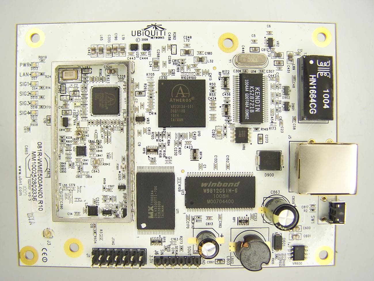
Click to zoom
Application Details
- Equipment Class
- DTS - Digital Transmission System
- Date of Grant
- Jun 20, 2011
- Application Purpose
- Original Equipment
- Date of Application
- Jun 20, 2011
- Equipment Note
- Long-Range 5GHz Station
- Frequency Range
- 5745.00000000 - 5825.00000000
- Company
- Ubiquiti Inc.
- Country
- United States
Documents & Files
Document Text
Text extracted from the exhibit documents filed with the FCC. Open a document above to read the original.
Users Manual
WS5 MANUAL The WS5 hi-power mini-PCI 802.11a radio card module has been specifically designed for use in outdoor wireless applications where additional link gain is critical. It is compatible with existing Atheros linux drivers and is capable of operation in the 5725-5850 MHz frequency range. Power and frequency limits are hard programmed into the radio card EEPROM, but card compatibility can be achieved with any Atheros Linux based software. It is necessary that the system integrators perform all applicable retesting and certification for their final system configurations. EXAMPLE OEM SYSTEM USAGE MODULAR USAGE PC ENGINES WRAP Wireless Router Board ATHEROS PUBLIC MADWIFI Driver Ubiquiti Networks, Inc. 778 N. First St. San Jose, CA 95112 (408)-385-1103 WS5 Pac Wireless Roo Tenna Antenna/Enclosure Software Driver 802.11a Long-Range 5GHz Station WS5 IMPORTANT MODULAR APPROVAL INFORMATION This device is intended only form OEM integrator under the fo llowing conditions: 1) The antenna must be installed such that 86.2 cm is maintained between the antenna and users, and 2) The transmitter module may not be co-located wit h any other transmitter or antenna. IMPORTANT NOTE: In the event that these conditions cannot be met (for example certain laptop configurations or co-location with another transmitter), then the FCC authorization is no longer considered valid and the FCC ID cannot be used on the final product. I n these circumstances, the OEM integrator will be responsible for re-evaluating the end product (including the transmitter) and obtaining a separate FCC authorization. End Product Labeling This transmitter module is authorized only f or use in devices where the antenna may be installed such that 86.2 cm may be maintained between the antenna and users (for example access points, routers, wireless ADSL modems, and similar equipment). The final end product must be labeled in visible area with the following: “Contains TX FCC ID SWX-WS5: End Product Manual Info rmation The user manual for end users must include the following information in a prominent location “IMPORTANT NOTE: To comply with FCC RF exposure compliance requirements, the antenna used for this transmitter must be installed to provide a separation distance of at least 86.2 cm from all persons and must not be co-located or operating in conjunction with any other antenna or transmitter.” WS5 IMPORTANT OPERATION INFORMATION Safety Information 86.2 cm NOTE: This equipment has been tested and found to comply with the limits for a Class A digital device, pursuant to part 15 of the FCC Rules. These limits are designed to provide reasonable protection against harmful interference when the equipment is operated in a commercial environment. This equipment generates, uses, and can radiate radio frequency energy and, if not installed and used in accordance with the instruction manual, may cause harmful interference to radio communications. Opera- tion of this equipment in a residential area is likely to cause harmful interfer- ence in which case the user will be required to correct the interference at his own expense. FCC Notice to Users and Operators
Cover Letter(s)
91 E. Tasman Dr. | San Jose, CA 95134 | U.S.A. | Tel. 1-408-942-3085| Fax 1-408-351-4973. May 9, 2011 Subject: Signing Authority for Agency Approvals Dear Regulatory Authority, Please accept this letter authorizing Jennifer Sanchez of Ubiquiti Networks to act on my behalf as the point of contact for any FCC or Industry Canada filings and submissions for Grantee Code SWX and Industry Canada Company Number 6545A. Sincerely, Robert Pera CEO/Founder Ubiquiti Networks
Cover Letter(s)
91 E. Tasman Dr. | San Jose, CA 95134 | U.S.A. | Tel. 1-408-942-3085| Fax 1-408-351-4973. Ubiquiti Networks, Inc. 91 E. Tasman San Jose, CA 95134 May 9, 2011 MET Laboratories, Inc. 914 West Patapsco Avenue Baltimore, MD 21230 RE: CONFIDENTIALITY REQUEST FOR WispStation5 (FCC ID: SWX-WS5) To Whom It May Concern: This letter serves as an official request for confidentiality under FCC Rule Section 0.457 & 0.459. We request that the schematics, block diagram and theory of operation required to be submitted with this application be withheld from public review. These documents contain proprietary information that would sacrifice our competitive advantage in the marketplace if made public. Please contact me if there is any information you may need. Sincerely, Robert J. Pera President
Cover Letter(s)
91 E. Tasman Dr. | San Jose, CA 95134 | U.S.A. | Tel. 1-408-942-3085| Fax 1-408-351-4973. Ubiquiti Networks, Inc. 91 E. Tasman San Jose, CA 95134 May 16, 2011 Dear Application Examiner, Ubiquiti Networks, FCC ID: SWX-WS5, would like to have your authorization as a modular approval specific to Mini PCI module. The requirements of Public Notice DA00-1407 have been met and shown on the following statements. 1. “The modular transmitter must have its own RF shielding.”: Refer to external photos. 2. “The modular transmitter must have buffered modulation/data inputs.”: All inputs to the modules are buffered through logic or microprocessor inputs. 3. “The modular transmitter must have its own power supply regulation.”: Internal 2.5V/3.3V power regulator. Refer to block diagram. 4. “The modular transmitter must comply with the antenna requirements of section 15.203 and 15.204(C).”: The device is equipped with a unique antenna connector. Refer to external photos. 5. “The modular transmitter must be tested in a stand-alone configuration”: The device was tested in an adapter which exposed it outside that of a host laptop. 6. “The modular transmitter must be labeled with its own FCC ID number.”: There is one FCC ID submitter. A second FCC ID will be obtained by OEM customers for use in their hosts 7. “The modular transmitter must comply with any specific rule or operating requirements applicable to the transmitter and the manufacturer must provide adequate instructions along with the module to explain any such requirements.”: There are specific EEPROM settings inside the module that prohibit illegal usage. 8. “The modular transmitter must comply with any applicable RF exposure requirements.”: The module is NOT a portable device for laptops. Can only be used in mobile applications. Please contact me if there is any information you may need. Sincerely, Robert J. Pera President
ID Label/Location Info
FCC ID:SWX ‐ W W S5 IC : 6 F C 545A ‐ WS5 C C ID and IC ID a r r e imprinted on W W S5 module.
RF Exposure Info
§ 15.247(i) Maximum Permissible Exposure RF Exposure Requirements: §1.1307(b)(1) and §1.1307(b)(2): Systems operating under the provisions of this section shall be operated in a manner that ensures that the public is not exposed to radio frequency energy levels in excess of the Commission’s guidelines. RF Radiation Exposure Limit: §1.1310: As specified in this section, the Maximum Permissible Exposure (MPE) Limit shall be used to evaluate the environmental impact of human exposure to radiofrequency (RF) radiation as specified in Sec. 1.1307(b), except in the case of portable devices which shall be evaluated according to the provisions of Sec. 2.1093 of this chapter. Test Results: The EUT was compliant with the requirements of this section. MPE Limit Calculation: EUT’s operating frequency is 5745 – 5825 MHz;. Highest conducted power = 467.7 mW (i.e. 26.7 dBm). Therefore, Limit for Uncontrolled exposure: 1 mW/cm 2 . Equation from page 18 of OET 65, Edition 97-01 S = P G/ 4R 2 where, S = Power Density mW/m 2 P = Power (mW) R = Distance to the center of radiation of the antenna G = Maximum antenna gain Maximum antenna gain for EUT = 23 dBi = 199.5 P = 467.7 mW S = 1 mW/ cm 2 G = 199.5 R = sqrt {467.7*199.5 / 4()(1)} R = 86.2 cm Therefore, EUT meets the Uncontrolled Exposure limit at 86.2 cm. Test Engineer(s): Dusmantha Tennakoon Test Date(s): 03/10/11
RF Exposure Info
ARC Wireless Solutions, Inc. ● 10601 I-70 Frontage Rd. N ● Wheat Ridge, CO 80033-2660 ● Phone 303.421.4063 ● Toll Free 800.508.6532 ● [email protected] www.antennas.com “Patented Antenna Solutions” Specifications subject to change without notice 4.94-4.99GHz 19dBi & 5.15-5.875GHz 23dBi Panel Antenna for ARC IES™, Integrated Enclosure Solution Ordering Information Part # Description ARC-IA5823B02 4.94/5.875GHz 19/23dBi, R/A SMA Jack Shipping Information Sizes and Weights Description 14in x 11in x 14in (35.6cm x 27.9cm x 35.6cm) 25lb, (11.34kg) Antenna Packaging includes 10 antennas in a single over pack box Don’t see what you need? Contact us to discuss alternate configurations. Rev 113009 Electrical Specifications Frequency Range 4.94-4.99GHz/5.15-5.875GHz Gain 19dBi/23dBi 3dB Beamwidth Vertical/Horizontal 10deg/10deg Polarization Single linear, horizontal or vertical VSWR ≤1.5:1 typ., ≤1.7:1 max. Front-to-Back Ratio >40 dB Cross Polarization >30 dB Power Rating 30 watts Impedance 50 ohms Lightning Protection DC ground Connector Type R/A SMA Jack ♦ High gain, low cost circuit design ♦ Low profile and rugged design for outdoor use ♦ US Engineered ♦ Manufactured under strict US quality control procedures ♦ Fits with ARC’s IES™, Integrated Enclosure Solution SOLD SEPARATELY— Part # ARC-IE1001K99 or ARC-IE2000K01 (Gen II); ARC ABS™, Articulating Bracket Solution included with ARC-IE2000K01 ♦ Custom Enclosures Available See www.antennas.com for warranty information Page 1 of 2 ARC-IA5823B02 ARC Wireless Solutions, Inc. ● 10601 I-70 Frontage Rd. N ● Wheat Ridge, CO 80033-2660 ● Phone 303.421.4063 ● Toll Free 800.508.6532 ● [email protected] www.antennas.com “Patented Antenna Solutions” Specifications subject to change without notice 4.94-4.99GHz 19dBi & 5.15-5.875GHz 23dBi Panel Antenna for ARC IES™, Integrated Enclosure Solution Don’t see what you need? Contact us to discuss alternate configurations. Rev 113009 RF Patterns Horizontal Cut, typ. RF Patterns Vertical Cut, typ. -40 -30 -20 -10 0 30 210 60 240 90 270 120 300 150 330 180 0 -40 -30 -20 -10 0 30 210 60 240 90 270 120 300 150 330 180 0 Mechanical and Environmental Specifications Length x Width x Depth 13.3in x 13.3in x .43in (33.8cm x 33.8cm x 1.1cm) Weight 2.02lb (.92kg) Backplane Aluminum Enclosure Gray, Powder-coated die-cast aluminum Radome Gray, Injection Molded UV stabi- lized ABS plastic Wind Survivability 125mph (201kph) Wind Load 1.23ft² (0.12m²) Operating Temperature Range -49°F to +149°F (-45°C to +65°C) Pole Mount Diameter Range 0.75in to 3.0in (1.9cm to 7.6cm) See www.antennas.com for warranty information Page 2 of 2
Test Setup Photos
Photograph 1. Conducted Emissions, Test Setup Photograph 2. Radiated Emission, Test Setup Photograph 3. Conducted Emissions, 15.207(a), Test Setup
Contact Information
Applicant
Alex Macon
Technical Contact
Ubiquiti Networks, Inc.Rajesh Koganti
[email protected]408-396-6525
91 E. Tasman · San Jose, California · United States
Non-Technical Contact
Ubiquiti Networks, Inc.Jennifer Sanchez
[email protected]408-829-1603
Test Firm
MET Laboratories, IncorporatedRobert Frier
Technical Specifications
| # | Rule Parts | Frequency Range | Power Output |
|---|---|---|---|
| 1 | 15C | 5.75 GHz - 5.83 GHz | 467.70 mW |
Other Applications from Ubiquiti Inc.
SWX-USLGGH
Aug 20, 2026SuperLink Gateway HA
Equipment Class
DTS - Digital Transmission SystemSWX-UTRLR
Aug 19, 2026Digital Transmission Radio
Equipment Class
DTS - Digital Transmission SystemSWX-USLER
Aug 12, 2026Recessed Entry Sensor
Equipment Class
DSS - Part 15 Spread Spectrum TransmitterSWX-UVCG6ED
Jul 07, 2026G6 Edge Dome
Equipment Class
DTS - Digital Transmission SystemSWX-UVCG6ET
Jul 07, 2026G6 Edge Turret
Equipment Class
DTS - Digital Transmission System