SX8-BXRBXR Hand Held Tag Reader
Bartec USA LLC.
Click to zoom
Application Details
- Equipment Class
- DXX - Part 15 Low Power Communication Device Transmitter
- Date of Grant
- Apr 05, 2005
- Application Purpose
- Original Equipment
- Date of Application
- Apr 05, 2005
- Equipment Note
- BXR Hand Held Tag Reader
- Frequency Range
- 309.00000000 - 309.00000000
- Company
- Bartec USA LLC.
- Country
- United States
Documents & Files
Document Text
Text extracted from the exhibit documents filed with the FCC. Open a document above to read the original.
Users Manual
BXR HLF-C 2005 USER MANUAL Bartec Auto ID BXR HLF-C 2005 Rugged Hand Held Tag Reader 2 Table OF Contents Cover Page page 1 Table of Contents page 2 Class A Device Statement page 3 Product Overview page 4-5 Theory of Operation page 6 Tag reader Sequence of Operation page 6 Introduction Power up Instructions page 6 Navigating Menus page 6-7 Clear key Arrow keys Operation Cycle page 8 Menu Setup page 9-12 Power Supply page 13-18 Additional Information page 19 Environmental BXR HLF-C 2005 Technical Brief Enclosure 3 Class A Device Statement: (Section 15.105(a) of the FCC Rules) Note: This equipment has been tested and found to comply with the limits for a Class A digital service, pursuant to part 15 of the FCC Rules. These limits are designed to provide reasonable protection against harmful interface when the equipment is operated in a commercial environment. This equipment generates, uses, and can radiate radio frequency energy and, if not installed and used in accordance with the instruction manual, may cause harmful interference to radio communications. Operation of this equipment in a residential area is likely to cause harmful interface in which case the user will be required to correct the interface at there own expense. 4 Product Overview The Bartec BXR HLF-C unit is a rugged hand held radio tag reader configured to read TPMS sensors when installed in a wheel. The sensor is activated by means of a low frequency (125KHz) magnetic field. This is emitted from the round antenna attached to the front of the unit. Antenna Housing (Integral Laser Module) Trigger Keypad LC Display The magnetic field is activated by means of a trigger located on the front of the unit. The magnetic field or other features are selected from the menu driven system controlled by the keypad. There is a liquid crystal display (LCD) of 4 lines of 20 characters. This is used to display menus, and to display the sensor's ID number. 5 LEDs There are also two LEDs on the rear of the reader that are visible while the reader is in use. The green LED indicates a good read, while the red LED indicates a failure to read a sensor. Both LEDs remain illuminated until the next sensor is read or after one minute elapses. A sounder is provided to indicate the reader is activating and decoding the TPMS and also indicates a successful read. 6 Theory of Operation Tag Reader While in the presence of the magnetic field, the TPMS becomes active and transmits its ID number by modulating the applied magnetic field. This is picked up by the reader's antenna and demodulated into an electrical signal that is filtered and processed by the reader. The reader then decodes the sensor's ID number and displays it on the LCD screen. Sequence of Operation Introduction The BXR range of readers has been developed to be easy and quick to use. This allows operators to become proficient within a short period and minimises the risk of user error. The BXR HLF-C 2005 will activate and read radio tags at ultra high frequency. The BXR HLF-C 2005 will activate and read radio tags and has additional bar code scanning capabilities. The bar code reader scans, displays and records the Vehicle Identification Number (VIN). The TAG reader will activate, display and record the TPM ident of all four wheels on the vehicle. For efficient operation, the reader utilises a tight structured menu system. Power up Instructions Hold trigger and quickly touch and release power button, continue to hold trigger until release trigger comes onto screen. Enter password 123456. Navigating the Menus There are two methods for navigating the menus. The first method is to use the UP/DOWN arrow keys to move to the desired function and pressing ENTER to select. The second method is to use the function number. Pressing the number will take you directly to the function. 7 Clear key Pressing CLEAR at any point in the operating sequence will return the user to the beginning of the complete sequence. That is, even if the user is on the last wheel to be recorded, pressing CLEAR will return the user to the start requiring all the VIN and wheels to be scanned and activated again. All data to this point will be lost. Arrow keys Using the arrow keys allows the operator to move between the operations as required. 8 Operation Cycle When the unit is first initialised, the display may indicate company or location and firmware version. The user will then be at the beginning of the operating cycle and will not see the main screen again unless the unit is re-booted. The unit’s antenna should be placed adjacent to the sensor before pulling the trigger. In most cases, the optimum position for the antenna is half over the sensor and half over the tire close but not touching the wheel. This is because the metal of the wheel attenuates the magnetic field. Placing the antenna directly over the valve will probably result in an unsuccessful read. When the trigger is pressed, the unit immediately starts to generate the 125KHz magnetic field. The trigger must be held in until an audible tone is sounded and the UHF ID appears on screen. If the sensor is not read properly, read TPM ID try again, will appear on the screen. After receiving the UHF ID the user may enter another information screen by pressing the up arrow key. The PSI, temperature in Celsius, tool, check pass or fail, battery, and rotating or not rotating, will all appear on the screen. 9 Menu Setup Main Menu Options 1. Set Mode 1. Scan + 4 tires 2. Scan + 5 tires 3. Scan + spare 4. 4 tires only 5. 5 tires only 6. Spare tire only 7. Single wheel only 8. Exit this menu 2. Set Location 3. Test TPM Read 4. Select TPM Type 1. Schrader 1820 Man 2. Schrader 4096 Man 3. Schrader 1820 PWM 4. Schrader 4096 LP 5. Siemens LF16 6. Siemens LF32 7. Ford06 AC 8. Ford06 LB 9. TRW biphase A. Beru biphase B. Siemens AUTO 5. Select Barcode 1. no barcode 10 2. code 39 3. code 128 4. Test scan 6. Select UHF Mode 1. LF only 2. LF + 433 3. LF + 315 4. UHF only 5. 433 only 6. 315 …
Text truncated - open the document above for the full version.
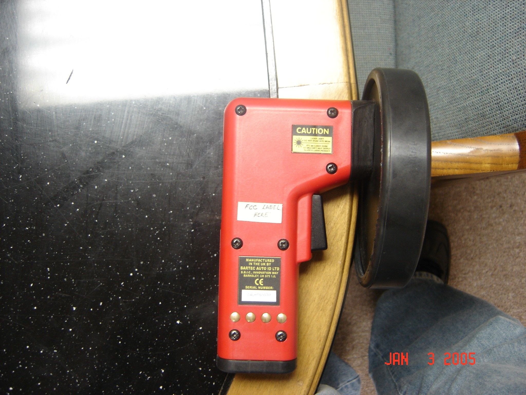
External Photos
LEDs Antenna Housing (Integral Laser Module) Trigger Keypad LC Display
Test Report
CONTENTS 1.0 GENERAL DESCRIPTION ........................................................................................................... 1 1.1 Related Submittals Grants................................................................................................................ 1 1.2 Product Description ......................................................................................................................... 1 1.3 Test Methodology ............................................................................................................................ 1 1.4 Test Facility ..................................................................................................................................... 1 2.0 SYSTEM TEST CONFIGURATION............................................................................................. 2 2.1 Justification ...................................................................................................................................... 2 2.2 EUT Setup........................................................................................................................................ 2 2.3 EUT Exercising Software ................................................................................................................ 2 2.4 Special Accessories.......................................................................................................................... 2 2.5 Equipment Modification .................................................................................................................. 2 2.6 Support Equipment List and Description.........................................................................................2 2.7 Test Configuration Block Diagrams ................................................................................................ 3 3.0 TEST RESULTS ............................................................................................................................. 4 3.1 Transmitting Time, FCC 15.231(a)(1) .............................................................................................5 3.2 Field Strength of Fundamental and Spurious Emissions, FCC 15.231(b), 15.209 .......................... 6 3.3 Bandwidth of Emissions, FCC 15.231(c) ........................................................................................ 7 3.4 Line Conducted Emissions, FCC 15.207 ......................................................................................... 8 3.5 Test Procedure ................................................................................................................................. 9 3.6 Field Strength Calculation ............................................................................................................. 10 4.0 TEST EQUIPMENT..................................................................................................................... 11 FCC ID: SX8-BXR February 2004 Page 1 of 20 1.0 GENERAL DESCRIPTION 1.1 Related Submittals Grants This is single application of the Bartec USA, LLC 309MHz Remote Control Transmitter for Certification under FCC Part 15, Subpart C. There are no other simultaneous applications. 1.2 Product Description BXR Transmitter is a RF remote control operating in 309MHz. RF Power Output: 10 mW maximum (10dBm) Antenna Description: Integrated antenna Sample Submitted: December 1, 2004 Test Work Started: December 2, 2004 Test Work Completed: December 3, 2004 1.3 Test Methodology Emission measurements were performed according to the procedures in ANSI C63.4-2000. All field strength radiated emissions measurements were performed in the semi-anechoic chamber, and for each scan, the procedure for maximizing emissions in Appendices D and E were followed. All field strength radiated tests were performed at an antenna to EUT distance of 3 meters, unless stated otherwise in the "Justification Section" of this Application. 1.4 Test Facility The test site facility used to collect the radiated and conducted measurement data is located at 7250 Hudson Blvd., Suite 100, Oakdale, Minnesota. This test facility has been fully described in a report dated on March 2003 submitted to FCC. Please reference the site registration number: 90706, dated April 18, 2003. FCC ID: SX8-BXR February 2004 Page 2 of 20 2.0 SYSTEM TEST CONFIGURATION 2.1 Justification N/A 2.2 EUT Setup For simplicity of testing, the transmitter was wired to transmit continuously 2.3 EUT Exercising Software N/A 2.4 Special Accessories There are no special accessories necessary for compliance of these products. 2.5 Equipment Modification No modifications were installed during the testing. 2.6 Support Equipment List and Description Junction Box, P/N: AF-CDJB-0001-01, S/N: 04CDJB1205 PSU/RS232 Interface, P/N: AF-CDI-0001-01, S/N: 04CD1205 FCC ID: SX8-BXR February 2004 Page 3 of 20 2.7 Test Configuration Block Diagrams The EUT was setup as tabletop equipment. The EUT was powered at 120VAC/60Hz. Field Strength Measurements FCC ID: SX8-BXR February 2004 Page 4 of 20 3.0 TEST RESULTS Data is included for the worst case configuration (the configuration which resulted in the highest emission levels). A sample calculation, configuration photographs, data tables and graphical representations of the emissions are included. The EUT is intended for operation under the requirements of Part 15 Subpart C. Specific test requirements include the following: 47 CFR 15.231(a)(1) Transmitting Time 47 CFR 15.231(b) Field Strength of Fundamental and Spurious Emissions 47 CFR 15.231(c) Bandwidth of Emissions 47 CFR 15.207 Line Conducted Emissions FCC ID: SX8-BXR February 2004 Page 5 of 20 3.1 Transmitting Time, FCC 15.231(a)(1) Measured total transmitting time after pressing the activation button is <1sec. According to FCC Part 15.231(a)(1) a manually operated transmitter should stop transmitting within 5 sec after release the activation button. Therefore the maximum transmitting…
Text truncated - open the document above for the full version.
Test Setup Photos
FCC ID: SX8-BXR February 2004 Page 19 of 20 Radiated Emissions Test Configuration Radiated Emissions Test Configuration FCC ID: SX8-BXR February 2004 Page 20 of 20 Conducted Emissions Test Configuration Conducted Emissions Test Configuration
Contact Information
Applicant
Scot A. Holloway(General Manager)
Technical Contact
Bartec USA LLCPaul Salisbury
[email protected]586-685-1300
44231 Phoenix Drive · Sterling Heights, Michigan · United States
Non-Technical Contact
Bartec USA LLCDeLynn Harm
[email protected]586-685-1300
Test Firm
Intertek Testing ServicesUri Spector
Technical Specifications
| # | Rule Parts | Frequency Range | Power Output |
|---|---|---|---|
| 1 | 15C | 309 MHz - 309 MHz | - |
Other Applications from Bartec USA LLC.
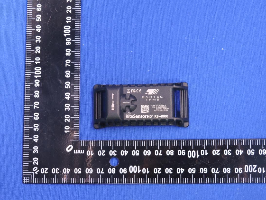
SX8RS4000
Mar 23, 2026Rite Sensor HD
Equipment Class
DSC - Part 15 Security/Remote Control Transmitter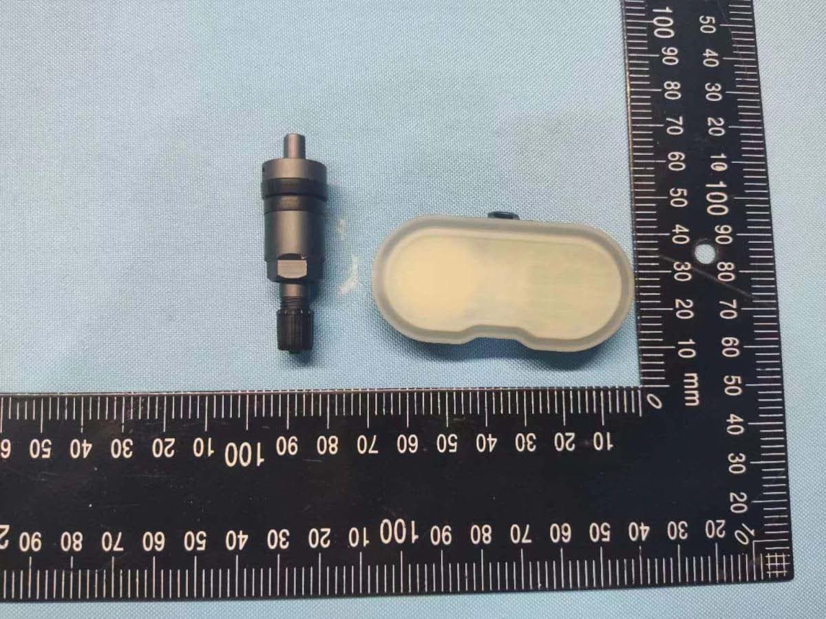
SX8-RS3000
Sep 21, 2022RITE-SENSOR BlueR
Equipment Class
DTS - Digital Transmission System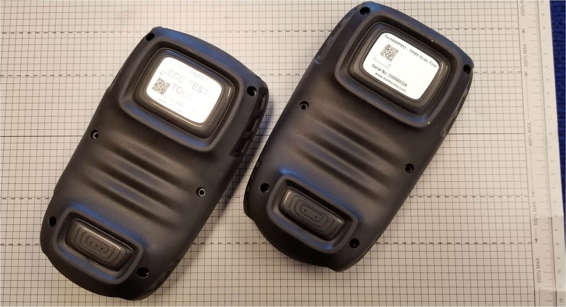
SX8DSW9
May 20, 2021LF TRANSMITTER
Equipment Class
DCD - Part 15 Low Power Transmitter Below 1705 kHz
SX8T500
Jul 08, 2013Tire Pressure Monitoring System Test Transmitter
Equipment Class
DCD - Part 15 Low Power Transmitter Below 1705 kHz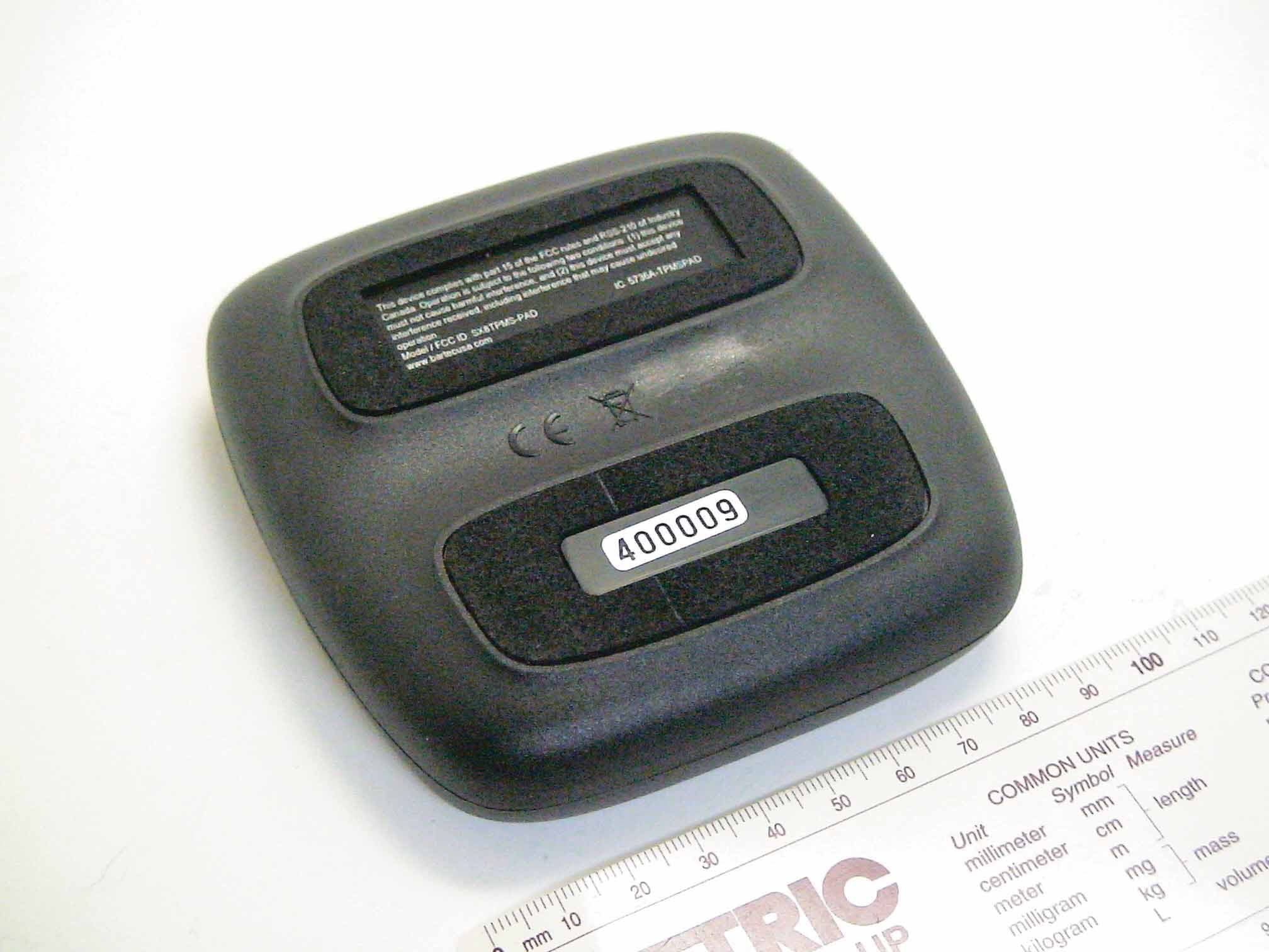
SX8TPMS-PAD
Oct 13, 2011Tire Pressure Programming Transmitter
Equipment Class
DCD - Part 15 Low Power Transmitter Below 1705 kHz