SX8T500Tire Pressure Monitoring System Test Transmitter
Bartec USA LLC.
Click to zoom
Application Details
- Equipment Class
- DCD - Part 15 Low Power Transmitter Below 1705 kHz
- Date of Grant
- Jul 08, 2013
- Application Purpose
- Original Equipment
- Date of Application
- Jul 08, 2013
- Equipment Note
- Tire Pressure Monitoring System Test Transmitter
- Frequency Range
- 0.12500000 - 0.12500000
- Company
- Bartec USA LLC.
- Country
- United States
Documents & Files
Document Text
Text extracted from the exhibit documents filed with the FCC. Open a document above to read the original.
Users Manual
Tech 500 User Guide rev1.0 JUNE 2013 1 TABLE OF CONTENTS IMPORTANT NOTICES 2 BEFORE YOU GET STARTED 3 TOOL LAYOUT 4 TOOL CONNECTIONS 5 POWER ON/OFF 6 CHARGING TOOL 7 TOOL DISPLAY AND ICONS 8 MENU SYSTEM TEST BEFORE YOU TOUCH RELEARN REVIEW DATA TOOLKIT MY TOOL 11 TOOL POSITIONING/READING A SENSOR 20 UPDATING YOUR TOOL (PC) 29 UPDATING YOUR TOOL (SD Card) 32 UPDATING YOUR TOOL (Wireless) APPENDIX A: INDUCTIVE CHARGING APPENDIX B: VIN 37 APPENDIX C: FAQ’S & TROUBLESHOOTING GUIDE 38 APPENDIX D: DEFINITIONS 39 APPENDIX E: TPMS SYSTEM REVIEW 40 APPENDIX F: COMS ERROR TROUBLESHOOTING 42 APPENDIX G: Technical Support 43 LIMITED WARRANTY 44 TOOL REGISTRATION 47 Tech 500 User Guide rev1.0 JUNE 2013 2 INCLUDED IN Tech500 KIT: Tech500 TPMS Tool [with protective Boot] SD Card [in the tool] Power Supply Re-Learn Magnet USB Cable DB15 to OBDII Cable Tech500 Quick Start Guide Tech500 User Guide Kit CD IMPORTANT NOTICES All specifications, illustrations and information contained within this manual are based on the most current information available at the time of publication. BartecUSA reserves the right to make changes at any time without obligation to notify any person or organization. BartecUSA will do its best to keep you the customer informed of any changes that might affect the tools performance. FCC Compliance Model: DSW FCC ID: SX8T500 IC: 5736A-T500 Contains FCC ID: QOQWT12 IC: 5123A-BGTWT12A Contains FCCID: YOPGS1011MIP IC: 9154A-GS1011MIP This device complies with Part 15 of the FCC Rules and with Industry Canada license-exempt RSS standard(s). Operation is subject to the following two conditions: (1) This device may not cause harmful interference, and (2) This device must accept any interference received, including interference that may cause undesired operation. Le présent appareil est conforme aux CNR d'Industrie Canada applicables aux appareils radio exempts de licence. L'exploitation est autorisée aux deux conditions suivantes : (1) l'appareil ne doit pas produire de brouillage, et (2) Tech 500 User Guide rev1.0 JUNE 2013 3 l'utilisateur de l'appareil doit accepter tout brouillage radioélectrique subi, même si le brouillage est susceptible d'en compromettre le fonctionnement. Note: Changes or modifications not expressively approved by the party responsible for compliance could void the user's authority to operate the equipment. Note: This equipment has been tested and found to comply with the limits for a Class A digital device, pursuant to Part 15 of the FCC Rules. These limits are designed to provide reasonable protection against harmful interference when the equipment is operated in a commercial environment. This equipment generates, uses, and can radiate radio frequency energy and, if not installed and used in accordance with the instruction manual, may cause harmful interference to radio communications. Operation of this equipment in a residential area is likely to cause harmful interference in which case the user will be required to correct the interference at their expense. BEFORE YOU GET STARTED Before you get started using your Tech500 TPMS tool, there are a few items to review. Charge your tool The Tech500 is shipped with a fully charged battery, but due to shelf drain it may require charging. It is recommended to charge your tool 2+ hours before use. (See page 6 for charging instructions) Register your tool You can register your Bartec Tech500 @ www.bartecusa.com. Follow the on-screen prompts filling in your information and tool serial Tech 500 User Guide rev1.0 JUNE 2013 4 number. A valid serial number and supplier is required to process your registration, which can take up to 24hrs once submitted. Update your Tool Once your tool is registered, verify the software level loaded to the level available online and update your tool if necessary. Refer to section on tool updating for further instruction. TOOL LAYOUT TOOL CONNECTIONS Tech 500 User Guide rev1.0 JUNE 2013 5 POWER ON/OFF SEQUENCE The Tech500 is powered up using the ON/OFF key. On/Off Key To power the unit on press the On/Off Key for approx 2 seconds – the display will light showing a logo and software version. The unit will then display the Main Menu. All data (results and settings) from previous tests is reloaded. Tech 500 User Guide rev1.0 JUNE 2013 6 Power down the Tech500 by using the same ON/ OFF key. On/Off Key (Hold, then release when ‘Goodbye’ is displayed.) Auto power off is after 5 minutes of inactivity. The unit automatically powers up when the charger or USB port is in use- auto power off is not operational. CHARGING TOOL NOTICE: Only use the power supply or USB cable that is included in the Tech500 tool kit to charge this tool. The use of un-approved power supplies may damage your tool and will void the tool warranty. Tech 500 User Guide rev1.0 JUNE 2013 7 The Tech500 comes with the rechargeable battery already installed. Battery replacement must be done at the factory. For optimum performance, always keep your Tech500 sufficiently charged. It is recommended that you charge the tool 2 + hours before first use. The charge port is located on the right side of the tool and is the USB port opening. TOOL DISPLAY AND ICONS # of selections # of selections USB indicator Data stored on tool Battery indicator Tech 500 User Guide rev1.0 JUNE 2013 8 The menu page number (e.g. x/y) on the status line indicates the menu page or item currently displayed. The first number- x- indicates the item number selected. The second- y- indicates the total number of items available. USB Indicator This status line indicator confirms the Tech500 is connected to the USB port of a computer. Once communication has been established, results data can be viewed on the pc via the Mass Storage Device feature. (Use the PC explorer program) “HTM File” When the USB lead is removed the USB icon will disappear. Battery Indicator/ Charging This status line Indicator will illustrate the remaining charge status of the battery. As di…
Text truncated - open the document above for the full version.
Cover Letter(s)
Willow Run Test Labs, LLC 8501 Beck Road, Building 2227 Belleville, Michigan 48111 USA Tel: (734) 252-9785 Fax: (734) 926-9785 e-mail: [email protected] Attn.:Federal Communications Commission Equipment Approval Services P.O. Box 358315 Pittsburgh, PA 15251-5315 Re: Certification for Bartec USA, LLC SX8T500 FCC ID: SX8T500 Please find enclosed application materials for certification of Bartec USA, LLC SX8T500. We tested it and found it to comply with CFR Title 47, Part 15.209. If there are any questions regarding the application or testing performed, please contact us at the above address or call (734) 252-9785, or e-mail [email protected]. Sincerely, Joseph D. Brunett Willow Run Test Labs, LLC 8
Cover Letter(s)
44231Phoenix Drive Sterling Hts., MI48314 (586)685-1300 fax: (586)323-3801 Telephone:(586) 685-1300 Fax:(586) 323-3801 On behalf of:Bartee USA LLC. 44231 Phoenix Drive Sterling Heights, MI 48314 E-mail:[email protected] Title:General Manager Dated this We certify that we are not subject to denial of federal benefits, that includes FCC benefits, pursuant to Section 5301 of the Anti-DrugAbuse Act of 1988, 21 U.S.c. 862. Further, no party, asdefined in 47 CFR 1.2002 (b), to the application is subject to denial of federal benefits, that includes FCCbenefits. Joseph D. Brunett,on behalf ofWillow Run Test Labs, LLe,is a uthorizedto act on behalf ofBartee USALLC.,until otherwise notified, for applications to American Certification Body, Inc. (ACB). Re: Letter of Agency for FCCCompliance Testing Federal Communications Commission Applications Processing Branch 7435 OaklandMills Road Colombia,MD 21046 Bartee -TPMS Tools, T raining and Supportsince 20001 \'.
Cover Letter(s)
Willow Run Test Labs, LLC 8501 Beck Road, Building 2227 Belleville, MI 48111 Phone: (734) 252-9785, Fax (734) 926-9785 e-mail:[email protected] Re:Certification for Bartec Electronics TPMS FCC ID:SX8T500 IC: 5736A-T500 REQUEST FOR CONFIDENTIALITY Pursuant to FCC 47 CRF 0.457(d) and 0.459 and IC RSP-100, Section 10, Bartec requests that a part of the subject application be held confidential. Bartec has spent substantial effort in developing this product and it is one of the first of its kind in industry. Having the subject information easily available to "competition" would negate the advantage they have achieved by developing this product. Not protecting the details of the design will result in financial hardship. Type of Confidentiality RequestedExhibit Short Term Permanent(1)ID Label & Location Short Term Permanent(3)External Photos Short Term Permanent 1 (4)Block Diagram Short Term Permanent(5)Schematics Short Term Permanent(7)Test Setup Photos Short Term Permanent(8)User’s Manual Short Term Permanent(9)Internal Photos Short Term Permanent(10)Parts List & Placement Short Term Permanent(11)RF Exposure Short Term Permanent 2 (12)Description of Operation 1.Block Diagram includes internal oscillator frequency information that the manufacturer considers to be proprietary. 2.A portion of the Description of Operation exhibit contains proprietary LF encoding information. Permanent Confidentiality:Bartec requests the exhibits listed above as permanently confidential be permanently withheld from public review. Short-Term Confidentiality (FCC Only):Bartec requests the exhibits selected above as short term confidential be withheld from public view for a period of 45 days from the date of the Grant of Equipment Authorization and prior to marketing. If there are any questions regarding this request, please contact me at the above address or call 734- 252-9785, fax 734-926-9785 or e-mail [email protected] Sincerely, Joseph D. Brunett, Ph.D. Willow Run Test Labs, LLC Check Box Check Box Check Box Check Box Check Box Check Box Check Box Check Box Check Box Check Box Check Box Check Box Check Box Check Box Check Box Check Box Check Box Check Box Check Box Check Box
RF Exposure Info
SAR / Health Hazard Requirement: According to CFR 15 §1.1307 (b)(1), systems operating under the provisions of this section shall be operated in a manner that ensures the public is not exposed to radio frequency energy levels in excess of the Commission’s guidelines. SAR Testing Exclusion for Included Modular Radio(s) Per FCC 447498 General RF Exposure Guidance v05, Section 4.3.1, the 10-g (hand-held) SAR test exclusion thresholds for 100 MHz to 6 GHz at test separation distances ≤ 50 mm are determined by the following formula SAR= P C d √ f GHz where d = minimum test distance in millimeters and Pc is the source-based time-averaged maximum conducted output power in milliwatts (or EIRP in milliwatts for a device without a removable antenna). The SAR threshold at a minimum test distance of 8 mm (e.g. distance from either module to the exterior surface of the EUT, as shown below) is thus computed to be: SAR Threshold for Mutually Exclusive Modular Radio Use Radio Module EIRP (dBm) EIRP (mW) dmin (mm) Computed SAR Threshold Value 10-g SAR Threshold (Avg) Bluetooth3.5*2.2480.447.5 WLAN14.39**27.4885.417.5 * As reported in Report No.: EF/2005/C0012, FCC ID: QOQWT12 ** As reported in Report No.: 31051809.001, FCC ID: YOPGS1011MIP Thus the EUT meets the test exclusion thresholds for 10-g SAR evaluation and complies with the regulations as a hand-held device.
Test Report
Date of Issue: June 26, 2013Prepared For: Bartec USA, LLCTest Report No.: 20130626-01 Willow Run Test Labs, LLC 8501 Beck Road, Building 2227 Belleville, Michigan 48111 USA Tel: (734) 252-9785 Fax: (734) 926-9785 e-mail: [email protected] Testing of Electromagnetic Emissions per USA: CFR Title 47, Part 15.209 Canada: IC RSS-210/GENe are herein reported for Bartec USA, LLC SX8T500 Test Report No.: 20130626-01 Copyright c ©2013 Applicant/Provider: Bartec USA, LLC 44231 Phoenix Drive, Sterling Heights Michigan 48314 United States Phone: (586) 685-1300, Fax: (586) 323-3801 Contact Person: Scot Holloway; [email protected] Measured by: Report Approved by: Dr. Joseph Brunett, EMC-002790-NEDr. Joseph Brunett, EMC-002790-NE Report by:Report Date of Issue:June 26, 2013 Dr. Joseph Brunett, EMC-002790-NE Results of testing the equipment under test (EUT) as completed on June 26, 2013 are as follows. Emissions:The transmitter fundamental emission meets the regulatory limit(s) by no less than 58.7 dB. Trans- mit chain spurious harmonic emissions comply by no less than 33.0 dB. Radiated spurious emissions associated with the receive chain of this device meet the regulatory limit(s) by no less than 5.6 dB. Unintentional spurious emissions from digital circuitry comply with the radiated emission limit(s) by more than 12.4 dB. AC Power Line conducted emissions comply by more than 6.4 dB. Willow Run Test Labs, LLC, 8501 Beck Road, Building 2227, Belleville, Michigan 48111 USAPage 1 of 21 Date of Issue: June 26, 2013Prepared For: Bartec USA, LLCTest Report No.: 20130626-01 Contents 1 Test Specifications, General Procedures, and Location4 1.1 Test Specification and General Procedures . . . . . . . . . . . . . . . . . . . . . . . . . . . . . . . . . .4 1.2 Test Location and Equipment Used . . . . . . . . . . . . . . . . . . . . . . . . . . . . . . . . . . . . . .5 2 Configuration and Identification of the Equipment Under Test6 2.1 Description and Declarations . . . . . . . . . . . . . . . . . . . . . . . . . . . . . . . . . . . . . . . . .6 2.1.1EUT Configuration . . . . . . . . . . . . . . . . . . . . . . . . . . . . . . . . . . . . . . . . . . .6 2.1.2Modes of Operation . . . . . . . . . . . . . . . . . . . . . . . . . . . . . . . . . . . . . . . . . .6 2.1.3Variants . . . . . . . . . . . . . . . . . . . . . . . . . . . . . . . . . . . . . . . . . . . . . . . . .7 2.1.4Test Samples . . . . . . . . . . . . . . . . . . . . . . . . . . . . . . . . . . . . . . . . . . . . . .7 2.1.5Functional Exerciser . . . . . . . . . . . . . . . . . . . . . . . . . . . . . . . . . . . . . . . . . .7 2.1.6Modifications Made . . . . . . . . . . . . . . . . . . . . . . . . . . . . . . . . . . . . . . . . . .7 2.1.7Production Intent . . . . . . . . . . . . . . . . . . . . . . . . . . . . . . . . . . . . . . . . . . .8 2.1.8Declared Exemptions and Additional Product Notes . . . . . . . . . . . . . . . . . . . . . . . .8 3 Emissions9 3.1 General Test Procedures . . . . . . . . . . . . . . . . . . . . . . . . . . . . . . . . . . . . . . . . . . . .9 3.1.1Radiated Test Setup and Procedures . . . . . . . . . . . . . . . . . . . . . . . . . . . . . . . . .9 3.1.2Conducted Emissions Test Setup and Procedures . . . . . . . . . . . . . . . . . . . . . . . . . . 11 3.1.3Power Supply Variation . . . . . . . . . . . . . . . . . . . . . . . . . . . . . . . . . . . . . . . . 11 3.1.4Thermal Variation . . . . . . . . . . . . . . . . . . . . . . . . . . . . . . . . . . . . . . . . . . . 11 3.2 Intentional Emissions . . . . . . . . . . . . . . . . . . . . . . . . . . . . . . . . . . . . . . . . . . . . . . 13 3.2.1Fundamental Emission Pulsed Operation . . . . . . . . . . . . . . . . . . . . . . . . . . . . . . 13 3.2.2Fundamental Emission Bandwidth . . . . . . . . . . . . . . . . . . . . . . . . . . . . . . . . . . 15 3.2.3Fundamental Emission . . . . . . . . . . . . . . . . . . . . . . . . . . . . . . . . . . . . . . . . . 17 3.3 Unintentional Emissions . . . . . . . . . . . . . . . . . . . . . . . . . . . . . . . . . . . . . . . . . . . . 18 3.3.1Transmit Chain Spurious Emissions . . . . . . . . . . . . . . . . . . . . . . . . . . . . . . . . . 18 3.3.2Radiated Receiver Spurious . . . . . . . . . . . . . . . . . . . . . . . . . . . . . . . . . . . . . . 19 3.3.3Radiated Digital Spurious . . . . . . . . . . . . . . . . . . . . . . . . . . . . . . . . . . . . . . . 20 3.3.4Conducted Emissions Test Results - AC Power Port(s) . . . . . . . . . . . . . . . . . . . . . . . 21 List of Tables 1Willow Run Test Labs, LLC Equipment List. . . . . . . . . . . . . . . . . . . . . . . . . . . . . . . . .5 2EUT Declarations. . . . . . . . . . . . . . . . . . . . . . . . . . . . . . . . . . . . . . . . . . . . . . . .6 3Pulsed Emission Characteristics (Duty Cycle). . . . . . . . . . . . . . . . . . . . . . . . . . . . . . . . 13 4Intentional Emission Bandwidth.. . . . . . . . . . . . . . . . . . . . . . . . . . . . . . . . . . . . . . 15 5Fundamental Radiated Emissions. . . . . . . . . . . . . . . . . . . . . . . . . . . . . . . . . . . . . . . 17 6Transmit Chain Spurious Emissions. . . . . . . . . . . . . . . . . . . . . . . . . . . . . . . . . . . . . . 18 7Receiver Chain Spurious Emissions≥30 MHz.. . . . . . . . . . . . . . . . . . . . . . . . . . . . . . 19 8Radiated Digital Spurious Emissions.. . . . . . . . . . . . . . . . . . . . . . . . . . . . . . . . . . . . 20 9AC Mains Power Conducted Emissions Results.. . . . . . . . . . . . . . . . . . . . . . . . . . . . . . 21 List of Figures 1Photos of EUT.. . . . . . . . . . . . . . . . . . . . . . . . . . . . . . . . . . . . . . . . . . . . . . . .6 2EUT Test Configuration Diagram. . . . . . . . . . . . . . . . . . . . . . . . . . . . . . . . . . . . . . .7 3Radiated Emissions Diagram of the EUT. . . . . . . . . . . . . . . . . . . . . . . . . . . . . . . . . . .9 4Radiated Emissions Test Setup Photograph(s). . . . . . . . . . . . . . . . . . . . . . . . . . . . . . . . 10 5Conducted Emissions Setup Diagr…
Text truncated - open the document above for the full version.
Contact Information
Applicant
Scot A. Holloway(General Manager)
Technical Contact
Willow Run Test Labs, LLCJoseph D. Brunett
[email protected]734-252-9785
8501 Beck Road · Belleville · United States
Test Firm
Willow Run Test Labs, LLCJoseph Brunett
Technical Specifications
| # | Rule Parts | Frequency Range | Power Output |
|---|---|---|---|
| 1 | 15C | 0.125 MHz - 0.125 MHz | - |
Other Applications from Bartec USA LLC.
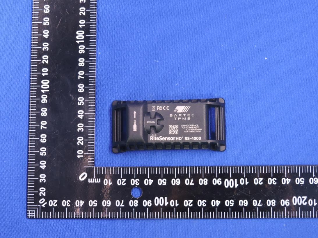
SX8RS4000
Mar 23, 2026Rite Sensor HD
Equipment Class
DSC - Part 15 Security/Remote Control Transmitter
SX8-RS3000
Sep 21, 2022RITE-SENSOR BlueR
Equipment Class
DTS - Digital Transmission System
SX8DSW9
May 20, 2021LF TRANSMITTER
Equipment Class
DCD - Part 15 Low Power Transmitter Below 1705 kHz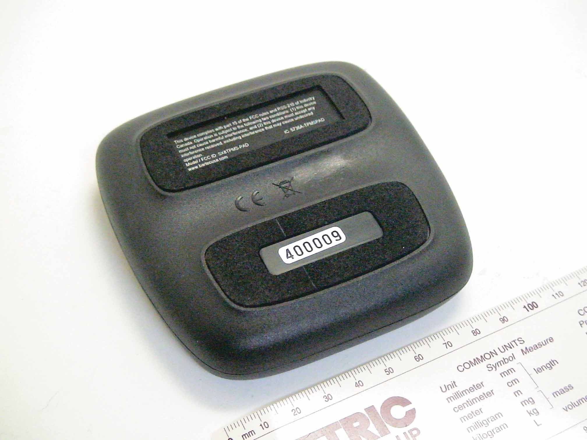
SX8TPMS-PAD
Oct 13, 2011Tire Pressure Programming Transmitter
Equipment Class
DCD - Part 15 Low Power Transmitter Below 1705 kHz
SX8-DSW
Mar 29, 2008Tire Pressure Sensor Diagnostic Tool
Equipment Class
DCD - Part 15 Low Power Transmitter Below 1705 kHz